Extron electronics ISM 482 User Manual
Integration scaling matrix switcher
Hide thumbs
Also See for ISM 482:
- Specifications (3 pages) ,
- User manual (96 pages) ,
- Assembly, installation and operation (2 pages)
Table of Contents
Advertisement
Quick Links
Advertisement
Table of Contents

Related Manuals for Extron electronics ISM 482


Summary of Contents for Extron electronics ISM 482
- Page 1 ISM 482 Integration Scaling Matrix Switcher 68-576-01 Rev. G 03 08...
- Page 2 Precautions Safety Instructions • English This symbol is intended to alert the user of important operating and maintenance (servicing) instructions in the literature provided with the equipment. This symbol is intended to alert the user of the presence of uninsulated dangerous voltage within the product’s enclosure that may present a risk of electric shock.
-
Page 3: Fcc Class B Notice
FCC Class B Notice This equipment has been tested and found to comply with the limits for a Class B digital device, pursuant to part 15 of the FCC Rules. These limits are designed to provide reasonable protection against harmful interference in a residential installation. This equipment generates, uses and can radiate radio frequency energy and, if not installed and used in accordance with the instructions, may cause harmful interference to radio communications. - Page 4 Quick Start — Integration Scaling Matrix Switcher Installation Step 1 Turn off power to the ISM ISM 482 and the input and output devices, and remove the power cords from them. Step 2 If desired, install an optional DVI output card into the switcher.
-
Page 5: Setup And Operation
If desired, connect a network WAN or LAN hub, a control system, or computer to the Ethernet RJ-45 port. For connection to a network hub, router, or switch, wire the network interface cable as a straight-through cable. For connection to a computer or control system, wire the network interface cable as a crossover cable. -
Page 6: Table Of Contents
Table of Contents Chapter 1 • Introduction About this Manual ... 1-2 About the Switcher ... 1-2 Features ... 1-4 Chapter 2 • Installation ... 2-1 Mounting the Switcher Tabletop placement ... 2-2 Rack mounting ... 2-2 UL requirements ... 2-2 Mounting instructions Cabling and Rear Panel Views Input connections ... - Page 7 Table of Contents, cont’d Advanced Configuration menu Test Pattern submenu Blue Only Mode and Edge Smoothing submenu Blanking submenu RGB Delay submenu Auto Imaging and Auto Memories submenu Enhanced Mode submenu Pixel Phase submenu PAL Film Mode submenu Reset submenu User Presets menu Save Preset submenu Erase Presets submenu...
- Page 8 Host-to-Switcher Instructions Switcher error responses ... 4-7 Using the command/response table ... 4-7 Command/response table for SIS commands ... 4-8 Command/respnse table for IP SIS Commands ... 4-13 Command/response table for special function SIS commands ... 4-14 Command/response table for advanced instruction set commands ... 4-16 Chapter 5 •...
- Page 9 Table of Contents, cont’d Chapter 7 • Maintenance and Modifications Opening and Closing the Switcher Installing a Firmware Upgrade Installing a DVI Output Card Appendix A • Ethernet Connection Cabling ... A-2 Determining Default Addresses Pinging to determine the switcher’s IP address ... A-3 Pinging to determine Web IP address ...
-
Page 10: About The Switcher
Integration Scaling Matrix Switcher Chapter One Introduction About this Manual About the Switcher Features... -
Page 11: About This Manual
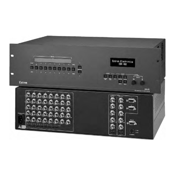
The switcher inputs all valid video signal formats on eight sets of five BNC connectors. The ISM 482 scales the input up or down to a wide variety of output resolutions and rates. The switcher outputs the scaled video, as RGBHV or RGBS, on two sets of output connectors, consisting of five BNCs and a 15-pin HD connector. - Page 12 The ISM receives and outputs the stereo audio on 5-pole captive screw connectors. For upscaling, the ISM 482 converts the horizontal and vertical sync timing and the number of lines of the lower-resolution video input to match the native resolution of the display.
-
Page 13: Features
Introduction, cont’d Features Inputs — Video inputs — The ISM switches among eight fully-configurable RGB, HDTV component video, component video, S-video, and composite video inputs on five BNC connectors per input. Audio inputs — The ISM switches among eight balanced or unbalanced stereo or mono audio inputs on 5-pole captive screw connectors. - Page 14 Memory presets — The ISM 482 has memory for up to 128 presets that allow the user to use RS-232 commands to save and recall color, tint, contrast, brightness, centering, sizing, and filtering information.
- Page 15 Introduction, cont’d Integration Scaling Matrix Switcher • Introduction...
-
Page 16: Chapter 2 • Installation
Integration Scaling Matrix Switcher Chapter Two Installation Mounting the Switcher Cabling and Rear Panel Views Configuration... -
Page 17: Mounting The Switcher
Installation Installation, cont’d Mounting the Switcher Four uninstalled rubber feet are included with the switcher. If you are going to rack mount the switcher, mount it before you cable it (see “Rack mounting”, below), and do not install the rubber feet. If you are not rack mounting the switcher, see “Tabletop placement”... -
Page 18: Mounting Instructions
Mounting instructions To rack mount the switcher, use two screws on each end of the switcher to attach the switcher to the rack (see figure 2-1). Figure 2-1 — Mounting the switcher Integration Scaling Matrix Switcher • Installation IS M F IL S IZ T IN... -
Page 19: Cabling And Rear Panel Views
50/60 Hz 1.2A MAX. H/HV Figure 2-2 — ISM 482 rear panel connectors Input connections AC power connector — Plug a standard IEC power cord into this connector to connect the switcher to a 100 to 240 VAC, 50 Hz or 60 Hz power source. - Page 20 Input audio connectors — Connect balanced or unbalanced stereo or mono audio sources to these 3.5 mm, 5-pole captive screw connectors. Connectors are included with the seamless switcher, but you must supply the audio cable. Figure 2-4 shows how to wire a connector for the appropriate input type. High impedance is generally over 800 ohms.
-
Page 21: Standard Output Connections
CAUTION CAUTION By default, the audio output follows the video switch. Audio breakaway, commanded via the front panel, the Ethernet link, or the RS-232 link, allows you to select from any one of the audio input sources. See chapter 3, “Operation”, chapter 4, “Programmer’s Guide”, chapter 5, “Switcher... -
Page 22: Optional Output Connection
Optional output connection DVI output connector (optional) — If the optional DVI output card is installed, connect a DVI/DFP-compatible video display to this DVI connector. This connector outputs the image selected for output 1 only. For output resolutions with less than 1024 pixels horizontally, the optional DVI output’s true horizontal resolution is limited to 1024 pixels. -
Page 23: Cabling And Rj-45 Connector Wiring
Installation, cont’d Cabling and RJ-45 connector wiring It is vital that your Ethernet cables be the correct cables, and that they be properly terminated with the correct pinout. Choosing a network cable Ethernet links use Category (CAT) 3, 4, 5, 5e, or 6, unshielded twisted pair (UTP) or shielded twisted pair (STP) cables, terminated with RJ-45 connectors. -
Page 24: Rs-232 Connection
RS-232 connection Remote port — Connect a host device, such as a computer or touch panel control, to the integration scaling matrix switcher via this 9-pin D connector for serial RS-232 control (figure 2-9). RS-232 — — — — — —... - Page 25 Installation, cont’d 2-10 Integration Scaling Matrix Switcher • Installation...
-
Page 26: Chapter 3 • Operation
Integration Scaling Matrix Switcher Chapter Three Operation Front Panel Controls and Indicators Front Panel Operations Optimizing the Video Optimizing the Audio Troubleshooting... -
Page 27: Front Panel Controls And Indicators
VIDEO VIDEO Press Press Press button button button AUDIO AUDIO AUDIO None Video Audio only only ADJUST BRT/ SIZE CENTER FILTER CONT MENU NEXT ISM 482 INTEGRATION SEAMLESS SWITCHER VIDEO LED key: = on, = off AUDIO Video & Audio... -
Page 28: Output Buttons And Leds
Output buttons and LEDs Output 1 and Output 2 buttons — The Output 1 and Output 2 buttons select output 1 or output 2. Press an output button to select that output and automatically deselect the other output (figure 3-3). Output 1 and 2 LEDs —... -
Page 29: Selecting An Input
Operation, cont’d Selecting an input Input selection buttons — The Input 1 through Input 8 buttons select the associated input to scale and display on the selected output(s). Input selection LEDs — The green input LEDs above the input buttons indicate the video selection. -
Page 30: Lcd Display
Brightness/Contrast control button — The Brightness/Contrast button selects the display brightness and contrast adjustments. The adjustment range for both brightness and contrast is from 0 to 63. Size control button — The Size button selects the display size adjustment. The adjustment range depends on the output resolution selected. Center control button —... -
Page 31: Front Panel Operations
(figure 3-6). An error-free power up self-test sequence leaves all of the LEDs off, with the exception of the selected output’s and input’s LEDs, off and the LCD cycling through the default displays. Extron Electronics Extron Electronics ISM 482 Power Integration sec. Scaling Matrix Version x.xx... -
Page 32: Menu System Overview
Menu system overview Figure 3-7 shows a flowchart of the main menus in the menu system. Power Extron Electronics ISM 482 Integration Scaling Matrix 2 sec. Extron Electronics ISM 482 60-425-01 Version x.xx 2 sec. Default Cycle Menu 10 sec. -
Page 33: Video & Audio Configuration Menu
Operation, cont’d From any menu or submenu, after 10 seconds of inactivity, the ISM saves all adjustment settings and times out to the default LCD display cycle. Video & Audio Configuration menu Figure 3-8 is a flowchart that shows an overview of the Video & Audio Configuration menu and the available settings. -
Page 34: Output Configuration Menu
Output Configuration menu Figure 3-9 is a flowchart that shows an overview of the Output Configuration menu, the submenus, and the available settings. Default Cycle Menu 10 sec. Video & Audio Configuration Menu Output Next Configuration Menu Advanced Configuration Menu User Presets Output resolutions See the table on the next... -
Page 35: Sync Type And Polarity Submenu
Operation, cont’d Resolution 50 Hz 56 Hz • 640 x 480 • 800 x 600 832 x 624 848 x 480 852 x 480 • 1024 x 768* • 1280 x 768* • 1280 x 1024* 1360 x 765* • 1365 x 768* 1365 x 1024 1366 x 768*... -
Page 36: Advanced Configuration Menu
The display or projector may require a particular combination of horizontal (H) and vertical (V) sync signal polarities. Select the appropriate combination of positive or negative H and V sync for the selected output by rotating the Adjust knob. If you need to set the sync type and polarity on the other output, press the other output button. -
Page 37: Test Pattern Submenu
0 lines. RGB Delay submenu The RGB Delay submenu displays and lets you set the RGB delay when a switch is made. With RGB delay, sync is never removed from the display. Rather, the ISM blanks the RGB (video) outputs while the scaler locks to the new sync, and then switches the RGB signals. -
Page 38: Auto Imaging And Auto Memories Submenu
Adjust knob to select On or Off. Select other inputs as necessary to configure. Reset submenu The Reset submenu resets all ISM 482 settings and adjustments to the default values and erases all presets. The front panel reset performs the same functions as zXXX SIS command (see chapter 4, “Programmer’s Guide”). -
Page 39: User Presets Menu
Operation, cont’d User Presets menu Figure 3-11 is a flowchart that shows an overview of the User Presets menu, the Save Preset and Erase Preset submenus, and the available settings. Default Cycle Menu 10 sec. Video & Audio Configuration Menu Output Configuration Menu... -
Page 40: Erase Presets Submenu
User presets are recalled using the Input buttons. See “Recalling a user preset”, earlier in this chapter, for instructions on recalling a user preset. Erase Preset submenu Select the output with the settings that you want to erase by pressing the desired Output button. -
Page 41: Picture Adjustments
3-16 Integration Scaling Matrix Switcher • Operation knob or the Adjust knob. Picture adjustment Extron Electronics Extron Electronics ISM 482 Integration Power Scaling Matrix Version xxxx 2 sec. SIZE... -
Page 42: Front Panel Security Lockout (Executive Mode)
Figure 3-14 — Front panel security lockout flowchart Integration Scaling Matrix Switcher • Operation knob to increase or knob to center the Press and hold both buttons simultaneously for 2 seconds COLOR/ CENTER TINT ISM 482 ISM 482 Executive Mode Enabled Disabled 3-17... -
Page 43: Ip Information
Operation, cont’d IP information To set up the ISM for operation via its Ethernet port, you need to know and be able to change the IP address. One way to do this is via the IP address and hardware address screen. To access the IP address and hardware address screen, press and hold the Color/Tint and Detail buttons while you apply power to the ISM (figure 3-15). -
Page 44: Setting Up A Dvd Source
If you are using a digital display such as an LCD or DLP projector, use the alternating pixels test pattern as a reference to adjust the phase and dot clock on the display devices. Proceed to step 2. If you are using a CRT display, use the cross hatch test pattern as a reference to converge the display. -
Page 45: Optimizing The Audio
Power on the audio sources, the switcher, and the audio players. Switch among the inputs (see “Selecting an input”, earlier in this chapter), listening to the audio with a critical ear or measuring the output audio level with test equipment, such as a VU meter. -
Page 46: Specific Problems
Specific problems The table below shows some common operating problems and their solutions. Problem Cause No image appears. The input signal is incompatible with the. compatible with the ISM. ISM. The input is improperly Use the Video & Audio configured. Freeze mode was entered via an SIS command when the... - Page 47 Operation, cont’d 3-22 Integration Scaling Matrix Switcher • Operation...
-
Page 48: Chapter 4 • Programmer's Guide
Integration Scaling Matrix Switcher Chapter Four Programmer’s Guide RS-232 Link Ethernet Link Symbols Switcher-Initiated Messages Host-to-Switcher Instructions... -
Page 49: Rs-232 Link
Programmer’s Guide RS-232 Link The switcher’s rear panel Remote 9-pin D female connector (figure 4-1) can be connected to the RS-232 serial port output of a host device such as a computer running the HyperTerminal utility or a control system. This connection makes software control of the switcher possible. -
Page 50: Ethernet Connection
Ethernet connection The cable can be terminated as either a patch cable or a crossover cable (figure 4-2) and must be properly terminated for your application: • Patch (straight) cable — Connection of the ISM to an Ethernet hub, router, or switcher that also hosts a controlling computer •... -
Page 51: Switcher-Initiated Messages
The switcher does not expect a response from the host; but, for example, the host program might request a new status. Power-up (c) Copyright 2002, Extron Electronics, ISM 482, Vx.xx The switcher initiates the copyright message when it is first powered on. Vxxxx is the firmware version number. -
Page 52: Picture Adjustments
Picture adjustments A front panel color adjustment has occurred. adjusted input and is the color variable. A front panel tint adjustment has occurred. adjusted input and is the tint variable. A front panel color brightness adjustment has occurred. tied to the adjusted input and A front panel contrast adjustment has occurred. -
Page 53: Rgb Delay
Programmer’s Guide, cont’d A front panel horizontal detail filter adjustment has occurred for the S-video or composite video input tied to output 1Blu The blue-only mode has been turned on or off from the front panel for one or both outputs. -
Page 54: Host-To-Switcher Instructions
The Auto Presets feature has been turned on or off from the front panel for all tie creations. is the on/off status. 1Enh The enhanced mode feature has been turned on or off from the front panel for S-video or composite video that is tied to one or both outputs. status for the two outputs. -
Page 55: Command/Response Table For Sis Commands
Programmer’s Guide, cont’d Command/response table for SIS commands Command ASCII Command (host to switcher) Creating ties Create video and audio tie Example: 1*2! Create video only tie Example: 5*2& Create audio only tie Read ties Read video and audio tie Read video only tie &... - Page 56 Command/response table for SIS commands (cont’d) Command ASCII Command (host to switcher) Brightness value specified is the output to which the adjusted input is tied. Set a specific brightness value Increment brightness value Decrement brightness value –Y View the brightness value Contrast value specified is the output to which the adjusted input is tied.
- Page 57 Programmer’s Guide, cont’d Command/response table for SIS commands (cont’d) Command ASCII Command (host to switcher) Bottom blanking Set a bottom blanking value Example: 2*5) Increment bottom blanking value Decrement bottom blanking value –) View the bottom blanking value Pixel phase Set a specific pixel sampling phase Increment sampling value...
- Page 58 Command/response table for SIS commands (cont’d) Command ASCII Command (host to switcher) Auto Memories Auto memories on Auto memories off View auto memories status User presets value specified is the output to which the input with the associated user preset is tied. Save user preset Recall user preset Freeze...
- Page 59 Programmer’s Guide, cont’d Command/response table for SIS commands (cont’d) Command ASCII Command (host to switcher) Executive mode Enable (lock image adjustments) Disable View the executive mode status Example: Verbose mode The default for verbose mode is on for the RS-232 connection and off for Ethernet connections. Disable (block reports) Disabling verbose mode blocks reports for front panel operations only, to this connection (RS-232 or Ethernet) only.
-
Page 60: Command/Response Table For Ip Sis Commands
Command/response table for SIS commands (cont’d) Command ASCII Command (host to switcher) Resets Zap all audio adjustments Zap all ISM settings zXXX Absolute reset ZQQQ Command/response table for IP SIS commands = ISM name = GMT Time and date (set) = Time and date (read) = IP address = Password... -
Page 61: Command/Response Table For Special Function Sis Commands
Programmer’s Guide, cont’d Command/response table for IP SIS commands Command ASCII Command (host to switcher) Set ISM name (location) Esc X30 Read ISM name (location) Set GMT/date Esc X31 The date and time entered should be Greenwich Mean Time (GMT). Read GMT/date Set IP address •... - Page 62 Command/response table for special function SIS commands (cont’d) Command ASCII Command (host to switcher) Blue screen Blue screen (blue & sync output only) Example: 1*8# Read blue screen Edge smoothing Edge smoothing *16# Example: 1*16# Read edge smoothing Enhanced mode Enhanced mode *12# Example:...
-
Page 63: Command/Response Table For Advanced Instruction Set Commands
Programmer’s Guide, cont’d Command/response table for advanced instruction set commands The advanced instruction set consist of four hexadecimal commands for uploading and downloading all or a portion of the switcher’s memory. These commands are for use by knowledgeable programmers, and result in a dump of data from (upload) or to (download) the switcher. -
Page 64: Chapter 5 • Switcher Software
Integration Scaling Matrix Switcher Chapter Five Switcher Software Control Software for Windows ® Button-Label Generator... -
Page 65: Control Software For Windows
Switcher Software Control Software for Windows The Windows-based Extron ISSISM Control Program communicates with the switcher via the Ethernet LAN port or the rear panel Remote RS-232/RS-422 port to provide an easy way to set up and operate the switcher. The program is compatible with Windows 2000 and Windows XP. -
Page 66: Software Operation Via Ethernet
Follow the on-screen instructions. By default, the installation of the installation routine creates a C:\Program Files\Extron\ISSISM directory, and it places the following five icons into a group folder named “Extron Electronics\ISSISM”: • Button-Label Generator- • Check for ISSISM Control Program Update •... -
Page 67: Using The Control Program
Switcher Software, cont’d Using the control program Many items found in the ISS/ISM Control Program are also accessible via front panel controls and the LCD menus (see chapter 3, “Operation”) and under SIS control (see chapter 4, “Programmer’s Guide”). The ISS/ISM Help Program provides information on settings and on how to use the control program, itself. - Page 68 The Extron ISS/ISM Control Program window (figure 5-5) appears. Figure 5-5 — Windows Control program window If desired, on the task bar click Tools > I/O Configuration to configure the video inputs and outputs in the I/O configuration window (figure 5-6). Figure 5-6 —...
-
Page 69: Using The Help Program
Switcher Software, cont’d If desired, on the task bar, click Tools > Audio Settings to set each input’s audio level or attenuation in the Audio Settings window (figure 5-7). Figure 5-7 — Control program Audio Settings window If desired, on the task bar, click Tools > IP Options to set the switcher’s IP parameters in the IP Settings/Options window (figure 5-8). -
Page 70: Installing The Software
Programs > Extron Electronics > Button-Label Generator. Extron’s Button-Label Generator window appears (figure 5-7). Under Systems selection, choose ISS 408/ISM 482. This selection creates the correctly sized labels for the ISM’s label strip. The button label editing area changes to reflect the number and arrangement of buttons on the device. - Page 71 Switcher Software, cont’d Integration Scaling Matrix Switcher • Switcher Software...
-
Page 72: Chapter 6 • Ethernet Operation
Integration Scaler Matrix Switcher Chapter Six Ethernet Operation Loading the Startup (Control) Page Control Page System Configuration Page File Management Page I/O Configuration Page... -
Page 73: Loading The Startup (Control) Page
Ethernet Operation Ethernet Operation, cont’d The ISM 482 can be controlled and operated through its Ethernet port, connected via a LAN or WAN, using a Web browser such as the Microsoft This chapter describes the factory-installed HTML pages, which are always available and cannot be erased or overwritten. - Page 74 Click the OK button. The switcher checks several possibilities, in the following order, and then responds accordingly. Does the address include a specific file name, such as 10.13.156.10/file_name.html? If so, the switcher downloads that HTML page. Is there a file in the switcher’s memory that is named “index.html”? If so, the switcher loads “index.html”...
-
Page 75: Control Page
Access the Control page by clicking the Control tab. Creating a tie Select and switch an input to an output as follows: Click the Video/Audio, Video, or Audio button to select both the video and audio planes, the video plane only, or the audio plane only for switching (audio follow or audio breakaway). -
Page 76: Freezing The Output
Freezing the output You can freeze either output by clicking the Output 1 or Output 2 Freeze button. The Freeze button turns blue. When the output is frozen, the input source can be removed and the ISM functions as a video store. Click the Freeze button again to toggle freeze mode off. -
Page 77: System Configuration Page
Ethernet Operation, cont’d System Configuration Page The ISM downloads the System Configuration page (figure 6-5) when you click the Configuration tab. The screen consists of fields in which you can observe and edit IP administration and system settings. Figure 6-5 — System Configuration page Access to the ISM settings using Web control is not password protected. -
Page 78: Administration Fields
Administration fields The administration fields on the System Configuration page are for entering and verifying administrator and user passwords. • Ethernet connection to the switcher, either by entering SIS commands via Telnet (see chapter 4, “Programmer’s Guide”) or using the control program (see chapter 5, “Switcher Software”) is password protected. -
Page 79: File Management Page
Ethernet Operation, cont’d File Management Page To delete files such as HTML pages from the ISM or to upload your own files to the ISM, click the File Management tab. The switcher downloads the file management Web page (figure 6-6). Figure 6-6 —... -
Page 80: I/O Configuration Page
I/O Configuration Page You can set up the input configurations and the output format on the I/O Configuration page (figure 6-7). Access the Setup page by clicking the I/O Config tab. Figure 6-7 — I/O Configuration page Input configuration You can specify the format of each input. The available formats are RGB, RGBcvS (identified as RGBcS in the drop-down box), YUVi, YUVp, Betacam 50, Betacam 60, HDTV, S-video, and composite video. -
Page 81: Output Resolution, Rate, Sync Format, And Polarity
Ethernet Operation, cont’d Output resolution, rate, sync format, and polarity The ISM 482 scales the input signal up or down to any of a number of output resolutions and rates. The switcher outputs the scaled video as RGBHV or RGBS, with user-selectable polarity, via either the program or preview connectors. -
Page 82: Output Resolution
Output resolution Select the output resolution as follows: Click in the resolution field. A drop-down scroll box appears (figure 6-9). Figure 6-9 — Resolution scroll box Click and drag the slider or click the scroll up ( ) or scroll down ( ) button until the desired rate is visible. -
Page 83: Output Format
Ethernet Operation, cont’d Output format Select between separate horizontal (H) and vertical (V) sync or composite (S) sync as follows: Click in the Type field. A drop-down box appears (figure 6-11). Figure 6-11 — Type drop box Click the desired sync type. Click the Submit button. -
Page 84: Chapter 7 • Maintenance And Modifications
Integration Scaling Matrix Switcher Chapter Seven Maintenance and Modifications Opening and Closing the Switcher Installing a Firmware Upgrade Installing a DVI Output Card... -
Page 85: Opening And Closing The Switcher
Disconnect from/ connect to J8 and J13. Extron ISM 482 Switcher Figure 7-1 — Removing the ISM cover Integration Scaling Matrix Switcher • Maintenance and Modifications To prevent electric shock, always unplug the ISM from the AC power source before opening the enclosure. -
Page 86: Installing A Dvi Output Card
Remove the top two front panel screws. Lift the top cover straight up approximately 5 inches until you can access the fan power cords. Do not touch any switches or other electronic components inside the CAUTION ISM. Doing so could damage the switcher. Electrostatic discharge (ESD) can damage IC chips even though you cannot feel it. -
Page 87: Installing A Firmware Upgrade
Extron recommends that you send the unit in to Extron for service and updates. U100 U101 Extron ISM 482 Switcher Figure 7-2 — ISM firmware chip locations • Chips U1 and U2 are replaced as a pair. • Chip U6 is replaced alone. -
Page 88: Installing A Dvi Output Card
Align the slots of each new firmware chip with the angled corners of the socket in the same orientation as the old chip. Gently, but firmly, press the chip into place in the socket. Close the switcher. See “Opening and Closing the Switcher”, starting with step 9 on page 7-3. - Page 89 Maintenance and Modifications, Cont’d If the rear panel DVI connector opening is still covered, remove the two screws that secure the cover to the back panel and remove the cover. Position the DVI card above connector J14 with the DVI connector facing toward the rear of the switcher.
-
Page 90: Appendix A • Ethernet Connection
Integration Scaling Matrix Switcher A ppendix A Ethernet Connection Cabling Determining Default Addresses Connecting as a Telnet Client... - Page 91 Ethernet Connection, cont’d The rear panel Ethernet connector (figure A-1) on the ISM switcher can be connected to an Ethernet LAN or WAN. This connection makes SIS control of the switcher possible using a computer connected to the same LAN. Cabling The Ethernet cables can be terminated as straight-through cables or crossover cables (figure A-1) and must be properly terminated for your application:...
-
Page 92: Determining Default Addresses
Determining Default Addresses To access the ISM switcher via the Ethernet port, you need the Extron ISM IP address. If the address has been changed to an address comprised of words and characters, the actual numeric IP address can be determined using the Ping utility. If the address has not been changed, the factory-specified default is 192.168.254.254. -
Page 93: Connecting As A Telnet Client
Ethernet Connection, cont’d Connecting as a Telnet Client The Microsoft Telnet utility is available from the DOS prompt. Telnet allows you to input SIS commands to the ISM from the PC via Ethernet. Access the DOS prompt and start Telnet as follows: Click Start >... -
Page 94: Escape Character And Esc Key
Once you are logged in, the ISM returns either Login Administrator or Login User. No further prompts are displayed until you break or disconnect the connection to the ISM. Escape character and Esc key When Telnet is first started, the utility advises that the Escape character is ‘Ctrl+]’. Many SIS commands include the keyboard may exist between the Escape character and the Escape key. - Page 95 Ethernet Connection, cont’d Integration Scaling Matrix Switcher • Ethernet Connection...
-
Page 96: Appendix B • Reference Information
Integration Scaling Matrix Switcher A ppendix B Reference Information Specifications Part Numbers Button Labels... -
Page 97: Specifications
Reference Information Specifications Video Routing ... 8 x 2 matrix Video input Number/signal type ... 8 RGBHV, RGBS, RGsB, RGBcvS, component video, S-video, composite video Connectors ... 8 x 5 female BNC Nominal level ... 1 Vp-p for Y of component video and S-video, and for composite video 0.7 Vp-p for RGB and for R-Y and B-Y of component video 0.3 Vp-p for C of S-video Minimum/maximum levels ... -
Page 98: Audio Output
Max input voltage ... 5.0 Vp-p Max. propagation delay ... 20 ns Polarity ... Positive or negative (selectable) Audio Routing ... 8 x 2 stereo matrix Gain ... Unbalanced output: 0 dB; balanced output: +6 dB Frequency response ... 20 Hz to 20 kHz, ±0.05 dB THD + Noise ... -
Page 99: Part Numbers
Warranty ... 3 years parts and labor All nominal levels are at ±10%. Specifications are subject to change without notice. Part Numbers Included parts These items are included in each order for an ISM 482: Included parts ISM 482 Rubber feet (self-adhesive) (4) IEC power cord Tweeker (small screwdriver) ISM 482 User’s Manual... -
Page 100: Cables And Connectors
Cables and connectors When using signals with a scanning frequency of 15-125 kHz and running distances of 100 feet or more, use high resolution BNC cables to achieve maximum performance. Bulk cable Extron Part RG6/super high resolution cable RG6 bulk , 500' (150m), single conductor RG6-1 bulk , 1000' (300m), single conductor RG6-5 bulk , 500' (150m), five conductor MHR-5 Cable (Non-plenum) - Page 101 Reference Information, cont’d Integration Scaling Matrix Switcher • Reference Information...
- Page 102 Integration Scaling Matrix Switcher • Reference Information...
- Page 103 Reference Information, cont’d Integration Scaling Matrix Switcher • Reference Information...
- Page 104 Extron Electronics warrants this product against defects in materials and workmanship for a period of three years from the date of purchase. In the event of malfunction during the warranty period attributable directly to faulty workmanship and/or materials, Extron Electronics will, at its option, repair or replace said products or components, to whatever extent it shall deem necessary to restore said product to proper operating condition, provided that it is returned within the warranty period, with proof of purchase and description of malfunction to: USA, Canada, South America,...
- Page 105 Extron Electronics, USA 1230 South Lewis Street Anaheim, CA 92805 800.633.9876 714.491.1500 FAX 714.491.1517 www.extron.com Extron Electronics, Asia Extron Electronics, Europe 135 Joo Seng Rd. #04-01 Beeldschermweg 6C PM Industrial Bldg., Singapore 368363 3821 AH Amersfoort, The Netherlands +800.7339.8766 +65.6383.4400 +800.3987.6673 +31.33.453.4040 FAX +65.6383.4664 FAX +31.33.453.4050...
Need help?
Do you have a question about the ISM 482 and is the answer not in the manual?
Questions and answers