Extron electronics ISM 482 User Manual
Integration scaling matrix switchers
Hide thumbs
Also See for ISM 482:
- Specifications (3 pages) ,
- User manual (105 pages) ,
- Assembly, installation and operation (2 pages)
Table of Contents
Advertisement
Quick Links
Download this manual
See also:
User Manual
Advertisement
Table of Contents

Subscribe to Our Youtube Channel
Related Manuals for Extron electronics ISM 482


Summary of Contents for Extron electronics ISM 482
- Page 1 ISM 482 & ISM 182 Integration Scaling Matrix Switchers 68-576-01 Rev. C 11 04...
- Page 2 Precautions Safety Instructions • English Warning This symbol is intended to alert the user of important operating and maintenance Power sources • This equipment should be operated only from the power source indicated on the product. This equipment is intended to be used with a main power system with a grounded (servicing) instructions in the literature provided with the equipment.
- Page 3 Each input Unbalanced Input (high impedance) has a 3.5 mm, 5-pole Turn off power to the ISM 182 or ISM 482 and the captive screw connector for input and output devices, and remove the power Ring balanced or unbalanced Sleeve (s) cords from them.
- Page 4 Quick Start — Integration Scaling Matrix Switcher, cont’d Step 8 Configure the outputs If desired, connect a network WAN or LAN hub, a 1. Press Menu > Menu > Next. control system, or computer to the Ethernet RJ-45 2. Rotate the Adjust knob to select the output port.
-
Page 5: Table Of Contents
Table of Contents Chapter 1 • Introduction ....................... 1-1 About this Manual ......................1-2 About the Switcher ......................1-2 Features ........................... 1-4 Chapter 2 • Installation ......................2-1 Mounting the Switcher ....................2-2 Tabletop placement ......................2-2 Rack mounting ........................2-2 Cabling and Rear Panel Views .................. - Page 6 Table of Contents, cont’d .................... 3-12 Blanking submenu ..................3-12 RGB Delay submenu ............ 3-13 Auto Imaging and Auto Memories submenu ................3-13 Enhanced Mode submenu ..................3-13 Pixel Phase submenu .................. 3-13 PAL Film Mode submenu ....................3-13 Reset submenu User Presets menu ......................
- Page 7 Chapter 5 • Switcher Software ..................5-1 Control Software for Windows ® .................. 5-2 Installing the software ...................... 5-2 Software operation via Ethernet ..................5-2 .................... 5-2 Ethernet protocol settings Using the control program ....................5-3 Using the help program ....................5-5 Button-Label Generator ....................
- Page 8 Table of Contents, cont’d Appendix A • Ethernet Connection ................A-1 Ethernet Link ........................A-2 Ethernet connection ......................A-2 Default address ......................... A-3 ..............A-3 Ping to determine the switcher’s IP address ................ A-3 Ping to determine the Web IP address Connect as a Telnet client ....................
-
Page 9: Chapter 1 • Introduction
Integration Scaling Matrix Switcher Chapter One Introduction About this Manual About the Switcher Features... -
Page 10: About This Manual
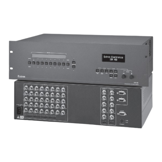
The switchers input all valid video signal formats on eight sets of five BNC connectors. The ISM 482 scales the input up or down to any of 40 output resolutions and rates. The ISM 182 scales the inputs to any of 20 resolutions and rates. - Page 11 The ISM receives and outputs the stereo audio on 5-pole captive screw connectors. For upscaling, the ISM 482 converts the horizontal and vertical sync timing and the number of lines of the lower-resolution video input to match the native resolution of the display.
-
Page 12: Features
Inputs — Video inputs — The ISM switches among eight fully-configurable RGB, HDTV component video (ISM 482), component video, S-video, and composite video inputs on five BNC connectors per input. Audio inputs — The ISM switches among eight balanced or unbalanced stereo or mono audio inputs on 5-pole captive screw connectors. - Page 13 Memory presets — The ISM 482 has memory for up to 128 presets that allow the user to use RS-232 commands to save and recall color, tint, contrast, brightness, centering, and sizing, and filtering information.
- Page 14 Introduction, cont’d Integration Scaling Matrix Switcher • Introduction...
-
Page 15: Chapter 2 • Installation
Integration Scaling Matrix Switcher Chapter Two Installation Mounting the Switcher Cabling and Rear Panel Views Configuration... -
Page 16: Mounting The Switcher
Installation Installation, cont’d Mounting the Switcher Four uninstalled rubber feet are included with the switcher . If you are going to rack mount the switcher, mount it before you cable it (see Rack mounting, below), and do not install the rubber feet. If you are not rack mounting the switcher, see Tabletop placement below. -
Page 17: Cabling And Rear Panel Views
H/HV H/HV ETHERNET Figure 2-2 — ISM 482 rear panel connectors Input connections AC power connector — Plug a standard IEC power cord into this connector to connect the switcher to a 100 to 240VAC, 50 Hz or 60 Hz power source. - Page 18 Installation, cont’d Input audio connectors — Connect balanced or unbalanced stereo or mono audio to these 3.5 mm, 5-pole captive screw connectors. Connectors are included with the seamless switcher, but you must supply the audio cable. Figure 2-4 shows how to wire a connector for the appropriate input type and impedance level.
-
Page 19: Output Connections
Output connections The two Output 1 outputs, consisting of five BNC connectors and a 15-pin HD connector, output the identical video signal and the same sync format. The two Output 2 outputs are also identical to each other. Video output BNC connectors— Connect RGB video displays to these two sets of female BNC connectors. -
Page 20: Ethernet Connection
Installation, cont’d Ethernet connection Ethernet port — If desired connect the switcher to an Ethernet LAN or WAN via this RJ-45 connector. Ethernet control allows the operator to control the switcher from a remote location. When connected to an Ethernet LAN or WAN , the switcher can be accessed and operated from a computer running a standard Internet browser. -
Page 21: Wiring The Network Cable
Wiring the network cable The cable can be terminated as either a patch cable or a crossover cable (figure 2-8) and must be properly terminated for your application: • Patch (straight) cable — Connection of the ISM to an Ethernet hub, router, or switcher that also hosts a controlling computer. -
Page 22: Rs-232 Connection
Installation, cont’d RS-232 connection Remote port — Connect a host device, such as a computer or touch panel control, to the Integration Seamless Matrix switcher via this 9-pin D connector for serial RS-232 control (figure 2-9). RS-232 Function — Not used Transmit data Receive data —... -
Page 23: Chapter 3 • Operation
Integration Scaling Matrix Switcher Chapter Three Operation Front Panel Controls and Indicators Front Panel Operations Optimizing the Video Optimizing the Audio Troubleshooting... -
Page 24: Front Panel Controls And Indicators
CENTER FILTER TINT CONT MENU NEXT ISM 482 ISM 482 INTEGRATION SEAMLESS SWITCHER Figure 3-1 — Integration Scaling Matrix Switcher front panel Video/Audio selection button and LEDs Video/Audio button — The Video/Audio button selects video, audio, video and audio, or neither for creating ties. -
Page 25: Outputs Buttons And Leds
Outputs buttons and LEDs Output 1 and Output 2 buttons — The Output 1 and Output 2 buttons select output 1 or output 2. Press an output button to select that output and automatically deselect the other output (figure 3-3). Output 1 and 2 LEDs —... -
Page 26: Selecting An Input
Operation, cont’d Selecting an input Input selection buttons — The Input 1 through Input 8 buttons select the associated input to scale and display on the selected output(s). Input selection LEDs — The green input LEDs above the input buttons indicate the video selection. -
Page 27: Lcd Display
Brightness/Contrast control button — The Brightness/Contrast button selects the display brightness and contrast adjustments. The adjustment range for both brightness and contrast is from 0 to 63. See Picture adjustments in this chapter. Size control button — The Size button selects the display size adjustment. The adjustment range depends on the output resolution selected. -
Page 28: Front Panel Operations
LEDs, with the exception of the selected output’s and input’s LEDs, off and the LCD cycling through the default displays. Default Display Cycle Extron Electronics Extron Electronics Out #1 In # 1 Output Rate ISM 482 ISM 482 0.00 kHz 0.00Hz #1 1280 x 1024 @ 60 Power Integration 60-425-01 Out #3 In # 3 S-Video sec. -
Page 29: Menu System Overview
Menu system overview Figure 3-7 shows a flowchart of the main menus in the menu system. Power Extron Electronics ISM 482 Integration Scaling Matrix 2 sec. Extron Electronics ISM 482 60-425-01 Version x . xx 2 sec. Default Cycle Menu 10 sec. -
Page 30: Video & Audio Configuration Menu
Operation, cont’d From any menu or submenu, after 10 seconds of inactivity, the ISM saves all adjustment settings and times out to the default LCD display cycle. Video & Audio Configuration menu Figure 3-8 is a flowchart that shows an overview of the Video & Audio Configuration menu and the available settings. -
Page 31: Output Configuration Menu
Output Configuration menu Figure 3-9 is a flowchart that shows an overview of the Output Configuration menu, the submenus, and the available settings. Default Cycle Menu 10 sec. Video & Audio Configuration Menu 10 sec. 10 sec. Menu Output #1 Resolution Output #1 Sync Type Output 1280 x 1024... -
Page 32: Sync Type And Polarity Submenu
Operation, cont’d ✝ ✝ ✝ ✝ ✝ ✝ ✝ ✝ ✝ ✝ e r f e r f Sync Type and Polarity submenu Select the output whose sync type and polarity you want to set by pressing the desired Output button. Rotate the Adjust knob while in this submenu to select the output video type (RGBHV or RGBS) for the selected output. -
Page 33: Advanced Configuration Menu
Advanced Configuration menu Figure 3-10 is a flowchart that shows an overview of the Advanced Configuration menu, the submenus, and the available settings. Default Cycle Menu 10 sec. Video & Audio Configuration Menu Press an output button to select an output. Select a test pattern Output with the Adjust... -
Page 34: Test Pattern Submenu
Operation, cont’d Test Pattern submenu The Test Pattern submenu lets you select from among several test patterns and assign the selected pattern to an output. The test patterns are helpful when adjusting the connected displays for color, convergence, focus, resolution, contrast, grayscale, and aspect ratio. -
Page 35: Auto Imaging And Auto Memories Submenu
Adjust knob to select On or Off. Select other inputs as necessary to configure. Reset submenu The Reset submenu resets all ISM 482 settings and adjustments to the default values and erases all presets. The front panel reset performs the identical functions as the zXXX SIS command (see chapter 4, Programmer’s Guide). -
Page 36: User Presets Menu
Operation, cont’d User Presets menu Figure 3-11 is a flowchart that shows an overview of the User Presets menu, the Save Preset and Erase Preset submenus, and the available settings. Default Cycle Menu 10 sec. Video & Audio Configuration Menu Output Configuration Menu... -
Page 37: Erase Presets Submenu
User presets are recalled using the Input buttons. See Recalling a user preset earlier in this chapter for instructions on recalling a user preset. Erase Preset submenu Select the output with the settings that you want to erase by pressing the desired Output button. -
Page 38: Picture Adjustments
Adjust an image for centering, sizing, brightness, contrast, color, tint, zoom, or detail as follows (figure 3-13): Extron Electronics Extron Electronics ISM 482 ISM 482 Integration 60-425-01 Display Power... -
Page 39: Front Panel Security Lockout (Executive Mode)
Default Cycle Press and hold both buttons simultaneously for 2 seconds COLOR/ CENTER TINT ISM 482 ISM 482 Executive Mode Executive Mode Enabled Enabled 10 sec. timeout Figure 3-14 — Front panel security lockout flowchart Integration Scaling Matrix Switcher •... -
Page 40: Ip Information
Operation, cont’d IP information To set up the ISM for operation via its Ethernet port, you need to know and be able to change the IP address. One way to do this is via the IP address and hardware address screen. To access the IP address and hardware address screen, press and hold the Color/Tint and Detail buttons while you apply power to the ISM (figure 3-15). -
Page 41: Setting Up A Dvd Source
If you are using a digital display such as an LCD or DLP projector, use the alternating pixels test pattern as a reference to adjust the phase and dot clock on the display devices. Proceed to step 3. If you are using a CRT display, use the cross hatch test pattern as a reference to converge the display. -
Page 42: Optimizing The Audio
Operation, cont’d Optimizing the Audio Each individual input audio level can be adjusted within a range of -24dB to +9dB, so there are no noticeable volume differences between sources and for the best headroom and signal-to-noise ratio. Adjust the audio gain and attenuation as follows: Connect audio sources to all desired inputs and connect the audio outputs to output devices such as audio players. -
Page 43: Specific Problems
Specific problems The table below shows some common operating problems and their solutions. Problem Cause Solution No image appears. The input signal is Connect an input device that is incompatible. compatible with the ISM. The input is improperly Use the Video & Audio configured. - Page 44 Operation, cont’d 3-22 Integration Scaling Matrix Switcher • Operation...
-
Page 45: Chapter 4 • Programmer's Guide
Integration Scaling Matrix Switcher Chapter Four Programmer’s Guide RS-232 Link Ethernet Link Symbols Switcher-Initiated Messages Host-to-Switcher Instructions... - Page 46 Programmer’s Guide RS-232 Link The switcher’s rear panel Remote 9-pin D female connector (figure 4-1) can be connected to the RS-232 serial port output of a host device such as a computer running the HyperTerminal utility or a control system. This connection makes software control of the switcher possible.
-
Page 47: Ethernet Connection
Ethernet connection The cable can be terminated as either a patch cable or a crossover cable (figure 4-2) and must be properly terminated for your application: • Patch (straight) cable — Connection of the ISM to an Ethernet hub, router, or switcher that also hosts a controlling computer. -
Page 48: Switcher-Initiated Messages
The switcher does not expect a response from the host, but, for example, the host program might request a new status. Power-up (c) Copyright 2002, Extron Electronics, ISM 482, Vx.xx The switcher initiates the copyright message when it is first powered on. Vxxxx is the firmware version number. -
Page 49: Picture Adjustments
Picture adjustments A front panel color adjustment has occurred. is the output number tied to the adjusted input and is the color variable. A front panel tint adjustment has occurred. is the output number tied to the adjusted input and is the tint variable. -
Page 50: Rgb Delay
Programmer’s Guide, cont’d 1Blu The blue-only mode has been turned on or off for one or both outputs from the front panel. is the on/off status for the either or both outputs. The leading “1” is meaningless. 1Fil The edge enhancement mode has been turned on or off for one or both outputs from the front panel. -
Page 51: Host-To-Switcher Instructions
1Enh The enhanced mode feature has been turned on or off from the front panel for S-video or composite video tied to one or both outputs. is the on/off status for the two outputs. The leading “1” is meaningless. Reconfig The input selected for the output has been adjusted using the Auto Image feature or a user preset. -
Page 52: Command/Response Table For Sis Commands
Programmer’s Guide, cont’d Command/response table for SIS commands Command ASCII Command Response Additional description (host to switcher) (switcher to host) Creating ties Create video and audio tie •In •All Select input to output Example: 1*2! Out2•In1•All Input 1 video and audio selected to output 2. - Page 53 Command/response table for SIS commands (cont’d) Command ASCII Command Response Additional description (host to switcher) (switcher to host) Brightness value specified is the output to which the adjusted input is tied. Set a specific brightness value Specify the brightness adjustment. Increment brightness value Increase the brightness.
- Page 54 Programmer’s Guide, cont’d Command/response table for SIS commands (cont’d) Command ASCII Command Response Additional description (host to switcher) (switcher to host) Bottom blanking Set a bottom blanking value Example: 2*5) 2Blb5 Blank the bottom five lines of the preview output. Increment bottom blanking value Increase blanking value 1 line.
- Page 55 Command/response table for SIS commands (cont’d) Command ASCII Command Response Additional description (host to switcher) (switcher to host) Auto Memories Auto memories on Set the ISM to apply auto memories settings to all inputs as selected. Auto memories off Set the ISM to not apply auto memories settings.
- Page 56 Programmer’s Guide, cont’d Command/response table for SIS commands (cont’d) Command ASCII Command Response Additional description (host to switcher) (switcher to host) Executive mode Enable (lock image adjustments) 1X Exe1 Lock front panel adjustments; adjust image via RS-232 only. Disable Exe0 Adjustments &...
- Page 57 Command/response table for SIS commands (cont’d) Command ASCII Command Response Additional description (host to switcher) (switcher to host) Resets Zap all audio adjustments ZapA Reset all audio levels to 0dB. Zap all ISM settings zXXX Zapx Reset all settings: All inputs: RGB Ouput: RGBHV 1024x768 @ 60Hz RGB delay: 1.0 sec.
-
Page 58: Command/Response Table For Special Function Sis Commands
Programmer’s Guide, cont’d Command/response table for IP SIS commands Command ASCII Command Response Additional description (host to switcher) (switcher to host) Set ISM name (location) Ipn• Esc X30 Read ISM name (location) Set GMT/date Ipt• Esc X31 The date and time entered should be Greenwich Mean Time (GMT). Read GMT/date Set IP address •... - Page 59 Command/response table for special function SIS commands (cont’d) Command ASCII Command Response Additional description (host to switcher) (switcher to host) Blue screen Blue screen :Output 1/2 Output 1/2 (blue & sync output only) 00 = Off/Off 02 = Off/On 01 = On/Off 03 = On/On Example: 1*8#...
-
Page 60: Command/Response Table For Advanced Instruction Set Commands
Programmer’s Guide, cont’d Command/response table for advanced instruction set commands The advanced instruction set consist of four hexadecimal commands for uploading and downloading all or a portion of the switcher’s memory. These commands are for use by knowledgeable programmers, and result in a dump of data from (upload) or to (download) the switcher. -
Page 61: Chapter 5 • Switcher Software
Integration Scaling Matrix Switcher Chapter Five Switcher Software Control Software for Windows ® Button-Label Generator... -
Page 62: Control Software For Windows
Switcher Software ® Control Software for Windows Two software programs accompany the ISM 182 and ISM 482: • The Extron ISS/ISM Control Program (Extron part #29-054-01), which communicates with the switcher via the rear panel Remote port, provides an easy way for you to control the switcher. -
Page 63: Using The Control Program
Using the control program Many items found in the ISS/ISM Control Program are also accessible via front panel controls and the LCD menus, see chapter 3, Operation, and under SIS control, see chapter 4, Programmer’s Guide. The ISS/ISM Help Program provides information on settings and on how to use the control program itself. - Page 64 Switcher Software, cont’d The Extron ISS/ISM Control Program window (figure 5-3) appears. Figure 5-3 — Windows Control program window If desired, on the task bar click Tools > I/O Configuration to configure the video inputs and outputs in the I/O configuration window (figure 5-4). Figure 5-4 —...
-
Page 65: Using The Help Program
If desired, on the task bar, click Tools > Audio Settings to set each input’s audio level or attenuation in the Audio Settings window (figure 5-5). Figure 5-5 — Control program Audio Settings window If desired, on the task bar, click Tools > IP Options to set the switcher’s IP parameters in the IP Settings/Options window (figure 5-6). -
Page 66: Installing The Software
Switcher Software, cont’d Installing the software The program is included on the same set of 3.5-inch diskettes as the ISS/ISM control program and is installed automatically when you install that program. It can also be downloaded from the Extron Web site (http://www.extron.com). By default, the Windows installation goes in either the C:\ISSISM directory, if installed automatically with the ISS/ISM Control Program or the C:\BUTTONS directory if installed as a stand-alone program. -
Page 67: Chapter 6 • Ethernet Operation
Integration Scaler Matrix Switcher Chapter Six Ethernet Operation Control Page System Configuration Page File Management Page I/O Configuration Page... -
Page 68: Load The Startup (Control) Page
Ethernet Operation Ethernet Operation, cont’d The ISM 182 and ISM 482 can each be controlled and operated through its Ethernet port, connected via a LAN or WAN, using a web browser such as Microsoft’s Internet Explorer. The browser’s display of the switcher’s status or operation has the appearance of web pages. - Page 69 The switcher checks several possibilities, in the following order, and then responds accordingly: Does the address include a specific file name, such as 10.13.156.10/file_name.html? If so, the switcher downloads that HTML page. Is there a file in the switcher ’s memory that is named “index.html”? If so, the switcher loads “index.html”...
-
Page 70: Control Page
Ethernet Operation, cont’d Control Page On the Control page (figure 6-1), you can select an input to either or both outputs. The Control page also provides facilities to check the frequency of an input and to mute outputs. Access the Control page by clicking the Control tab. Create a tie Select and switch an input to an output as follows: Click the Video/Audio, Video, or Audio button to select both the video and audio... -
Page 71: Freeze The Output
Freeze the output You can freeze either output by clicking the Output 1 or Output 2 Freeze button. The Freeze button turns blue. When the output is frozen, the input can be removed and the ISM functions as a video store. Click the Freeze button again to toggle freeze mode off. -
Page 72: System Configuration Page
Ethernet Operation, cont’d System Configuration Page The ISM downloads the System Configuration page (figure 6-5) when you click the Configuration tab. The screen consists of fields in which you can observe and edit IP administration and system settings. Figure 6-5 — System Configuration page Access to the ISM settings using web control is not password protected. -
Page 73: Administration Fields
Administration fields • Ethernet connection to the switcher, either by entering SIS commands (see chapter 4, Programmer’s Guide) or using the Control Program (see chapter 5, Switcher Software) is password protected. • Connection via HTML pages and connection via the RS-232 port are not password protected. -
Page 74: File Management Page
Ethernet Operation, cont’d File Management Page To delete files such as HTML pages from the ISM or to upload your own files to the ISM, click the File Management tab. The switcher downloads the file management HTML page (figure 6-6). Figure 6-6 —... -
Page 75: I/O Configuration Page
I/O Configuration Page You can set up the input configurations and the output format on the I/O Configuration page (figure 6-7). Access the Setup page by clicking the I/O Config tab. Figure 6-7 — I/O Configuration page Input configuration You can specify the format of each input. The available formats are RGB, RGBcvS (identified as RGBcS in the drop box), YUVi, YUVp, Betacam 50, Betacam 60, HDTV, S-video, and composite video. -
Page 76: Output Resolution, Rate, Sync Format, And Polarity
Ethernet Operation, cont’d Output resolution, rate, sync format, and polarity The ISM 482 scales the input up or down to any 1 of 40 output resolutions and rates. The ISM 182 scales the inputs to 1 of 20 resolutions and rates. Either switcher outputs the scaled video as RGBHV or RGBS, with user-selectable polarity, via either the program or preview connectors. -
Page 77: Output Resolution
Output resolution Select the output resolution as follows: Click the resolution field. A drop down scroll box appears (figure 6-9). Figure 6-9 — Resolution scroll box Click and drag on either the slider or click the scroll up ( ) or scroll down ( ) buttons until the desired rate is visible. -
Page 78: Output Format
Ethernet Operation, cont’d Output format Select between separate horizontal (H) and vertical (V) sync or composite (S) sync as follows: Click the Type field. A drop down box appears (figure 6-11). Figure 6-11 — Type drop box Click the desired sync type. Click the Submit button. - Page 79 Integration Scaling Matrix Switcher A ppendix A Ethernet Connection Ethernet Link...
-
Page 80: Appendix A • Ethernet Connection
Ethernet Connection, cont’d Ethernet Link The rear panel Ethernet connector (figure A-1) on the ISM switcher can be connected to an Ethernet LAN or WAN. This connection makes SIS control of the switcher possible using a computer connected to the same LAN. Ethernet connection The Ethernet cables can be terminated as straight-through cables or crossover cables (figure A-1) and must be properly terminated for your application:... -
Page 81: Default Address
Default address To access the ISM switcher via the Ethernet port, you will need the Extron ISM IP address. If the address has been changed to an address comprised of words and characters, the actual numeric IP address can be determined using the Ping utility. If the address has not been changed, the factory-specified default is 192.168.254.254. -
Page 82: Connect As A Telnet Client
Ethernet Connection, cont’d Connect as a Telnet client The Microsoft Telnet utility is available from the DOS prompt. Telnet allows you to input SIS commands to the ISM from the PC via the Ethernet link and the LAN. Access the DOS prompt and start Telnet as follows: Click on Start >... -
Page 83: Escape Character And Esc Key
Escape character and Esc key When Telnet is first started, the utility advises that the Escape character is ‘Ctrl+]’. Many SIS commands include the keyboard key. Consequently, some confusion may exist between the Escape character and the Escape key. The Telnet Escape character is a key combination, the key and the Ctrl pressed simultaneously, that returns you to the Telnet prompt while leaving the... - Page 84 Ethernet Connection, cont’d Integration Scaling Matrix Switcher • Ethernet Connection...
-
Page 85: Appendix B • Reference Information
Integration Scaling Matrix Switcher A ppendix B Reference Information Specifications Part Numbers Firmware Upgrade Installation Button Labels... - Page 86 Scaled resolutions 1,3,4,5 1,3,4,5 3,4,5 1,3,4,5 ISM 182 ......640x480 , 800x600 , 832x624 , 848x480 , 852x480 , 1024x768 ISM 482 ......640x480 1,3,4,5 , 800x600 1,3,4,5 , 832x624 3,4,5 , 848x480 , 852x480 , 1024x768 1,3,4,5 1280x768 , 1280x1024...
- Page 87 Audio Routing .......... 8 x 2 stereo matrix Gain ..........Unbalanced output: 0dB; balanced output: +6dB Frequency response ....20 Hz to 20 kHz, ±0.05dB THD + Noise ......... 0.03% @ 1 kHz at nominal level S/N ..........>90dB at rated maximum output Crosstalk ........
-
Page 88: Included Parts
MTBF ..........30,000 hours Warranty ........3 years parts and labor Specifications are subject to change without notice. Part Numbers Included parts These items are included in each order for an ISM 182 or ISM 482: Included parts Part number ISM 182 60-424-01... -
Page 89: Assorted Connectors
BNC-4 Mini HR Cable Part # BNC-4 Mini HR bulk, 500’ 22-032-02 BNC-4 Mini HR bulk, 1000’ 22-032-03 BNC-5 Mini HR Cable BNC-5 Mini HR bulk, 500’ 22-020-02 BNC-5 Mini HR bulk, 1000’ 22-020-03 Plenum BNC-5 Mini HR Cable Plenum BNC-5 Mini HR bulk, 500’ 22-103-02 Plenum BNC-5 Mini HR bulk, 1000’... -
Page 90: Firmware Upgrade Installation
Reference Information, cont’d Firmware Upgrade Installation In some cases the ISM’s firmware may require replacement with an updated version. There are nine user-replaceable firmware chips, U1, U2, and U6 on the front panel circuit board and U98, U99, U100, U101, U102, and U103 on the main circuit board. - Page 91 M AX 10 0- 1. 2A U101 Extron ISM 482 Switcher Figure B-1 — Removing the ISM cover Locate the firmware chip(s) to be replaced on the main or front panel circuit board (figure B-1). After you are electrically grounded, use a DIP chip puller to grasp the IC chip(s) and pull it (them) out of the socket.
-
Page 92: Button Labels
Reference Information, cont’d Secure the cover in place with the screws that were removed in steps 3 and 4. Rack mount the switcher if desired and reconnect all cables. Button Labels Eight sets of button labels are provided on the next page. Feel free to cut them out of the manual, write the applicable button information in each button area, and place them in the switcher’s label window. - Page 93 Integration Scaling Matrix Switcher • Reference Information...
- Page 94 Reference Information, cont’d B-10 Integration Scaling Matrix Switcher • Reference Information...
- Page 95 FCC Class B Notice This equipment has been tested and found to comply with the limits for a Class B digital device, pursuant to part 15 of the FCC Rules. These limits are designed to provide reasonable protection against harmful interference in a residential installation.
- Page 96 Extron Electronics, USA Extron Electronics, Europe Extron Electronics, Asia Extron Electronics, Japan 1230 South Lewis Street Beeldschermweg 6C 135 Joo Seng Road, #04-01 Daisan DMJ Building 6F Anaheim, CA 92805 3821 AH Amersfoort PM Industrial Building 3-9-1 Kudan Minami The Netherlands Singapore 368363 Chiyoda-ku, Tokyo 102-0074 Japan 714.491.1500...
Need help?
Do you have a question about the ISM 482 and is the answer not in the manual?
Questions and answers