
Subscribe to Our Youtube Channel
Related Manuals for Extron electronics DTP CrossPoint 84


Summary of Contents for Extron electronics DTP CrossPoint 84
- Page 1 User Guide Matrix Switcher DTP CrossPoint 84 Scaling Presentation Matrix Switchers with DTP Extension 68-2349-01 Rev. D 01 20...
- Page 2 Safety Instructions Safety Instructions • English Istruzioni di sicurezza • Italiano AVVERTENZA: Il simbolo, , se usato sul prodotto, serve ad WARNING This symbol, , when used on the product, is intended to avvertire l’utente della presenza di tensione non isolata pericolosa alert the user of the presence of uninsulated dangerous voltage within the all’interno del contenitore del prodotto che può...
- Page 3 Copyright © 2014-2020 Extron Electronics. All rights reserved. www.extron.com Trademarks All trademarks mentioned in this guide are the properties of their respective owners. The following registered trademarks ( ® ), registered service marks ( ), and trademarks ( ) are the property of RGB Systems, Inc. or Extron Electronics (see the current list of trademarks on the...
- Page 4 FCC Class A Notice This equipment has been tested and found to comply with the limits for a Class A digital device, pursuant to part 15 of the FCC rules. The Class A limits provide reasonable protection against harmful interference when the equipment is operated in a commercial environment.
- Page 5 Conventions Used in this Guide Notifications The following notifications are used in this guide: DANGER: • Will result in serious injury or death. • Entraînera des blessures graves ou la mort. WARNING: Potential risk of severe injury or death. AVERTISSEMENT : Risque potentiel de blessure grave ou de mort. Risk of minor personal injury.
-
Page 7: Table Of Contents
Configuring the TP Insertion Ports ....41 About this Guide ..........1 Selecting the Remote Port Baud Rate ... 42 About the DTP CrossPoint 84 Matrix Switchers ... 1 Background Illumination......... 42 DTP Input and Output Signals ......3 Setting the Front Panel Locks (Executive Definitions ............ - Page 8 Matrix Software ........70 DSP SIS Commands ....... 138 Software Operational Considerations and Command and Response Table for DSP SIS Installation ............71 Commands ............ 138 Software Operation via Ethernet ....71 DSP SIS Commands ........143 Software Operation via a USB Port ....71 Installing the Software ........
-
Page 9: Introduction
• DTP CrossPoint 84 • DTP CrossPoint 84 IPCP SA — Includes a stereo audio amplifier and a built-in Extron IPCP Pro 350 control processor DTP CrossPoint 84 IPCP MA — Includes a mono audio amplifier and a built-in Extron •... - Page 10 PC without programming long, obscure strings of code. SIS commands can be entered via the RS-232 port, USB port, or the LAN ports. The LAN ports can be connected through a local area network (LAN) or wide area network (WAN). DTP CrossPoint 84 Series Matrix Switchers • Introduction...
-
Page 11: Dtp Input And Output Signals
DTP CrossPoint switcher. Depending on the transmitting or receiving device, the DTP inputs and outputs can travel up to 330 feet (100 meters) or 230 feet (70 meters) without a loss of signal integrity. DTP CrossPoint 84 Series Matrix Switchers • Introduction... -
Page 12: Definitions
• When a preset consisting of one or more partial configurations is recalled, it overwrite only a portion of the current configuration, leaving other ties and settings unchanged. DTP CrossPoint 84 Series Matrix Switchers • Introduction... -
Page 13: Features
Compatible with DTP 230 Series and DTP 330 Series, plus XTP Matrix Switchers — Enables mixing and matching with desktop and wallplate transmitters and receivers, as well as other DTP-enabled products. The DTP CrossPoint 84 can also be integrated into an XTP System to provide connectivity between presentation spaces and a larger, facility-wide system. - Page 14 DMP 128 processor for AEC and audio system scalability. The expansion port allows the DTP CrossPoint 84 and any DMP 128 ProDSP Digital Matrix Processor model to be linked together via a single shielded Category (CAT) 6 cable for 16x8 channel transport between devices.
- Page 15 • • 1 x 100 watts @ 70 volts — The DTP CrossPoint 84 SA offers a stereo power amplifier with 50 watts per channel into 4 ohms and 25 watts per channel into 8 ohms, while the DTP CrossPoint 84 MA 70 offers a mono 70 volt power amplifier with 100 watts rms output.
- Page 16 50 feet (15 meters). Improves performance when using low quality cables. Automatic HDMI output reclocking — Reshapes and restores timing of digital video signals at each HDMI output, eliminating high frequency jitter to ensure reliable transmission over long cables. DTP CrossPoint 84 Series Matrix Switchers • Introduction...
- Page 17 (PCS) — Conveniently configure multiple products using a single software application. Rack-mountable 2U, full rack width metal enclosure Includes LockIt HDMI cable lacing brackets Internal universal power supply — The 100-240 VAC, 50/60 Hz, international power supply provides worldwide power compatibility. DTP CrossPoint 84 Series Matrix Switchers • Introduction...
-
Page 18: Installation
If desired, create and replace button labels (see Removing and Installing Button Labels on page 147). Ancillary operations … Install the Product Configuration Software and DSP Configurator software (see Matrix Software on page 70). DTP CrossPoint 84 Series Matrix Switchers • Installation... -
Page 19: Rear Panel Cabling And Features
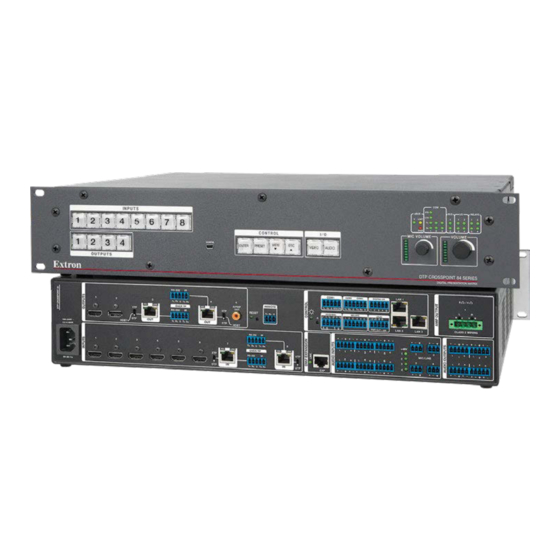
Amplified Output block only. Figure 2 shows the rear panel of a composite DTP CrossPoint 84 model, featuring elements of different models. Figure 3 shows only the Amplified Output block portion of the DTP CrossPoint 84 IPCP MA rear panel. -
Page 20: Video And Tp Input And Output Connections And Switches
HDMI output 1 and 2 — Connect HDMI cables between these ports and HDMI video displays. See HDMI connectors on page 16 for pin assignments and to use the LockIt HDMI Cable Lacing Bracket to secure the connector to the transmitter. DTP CrossPoint 84 Series Matrix Switchers • Installation... -
Page 21: Audio Input And Output Connections
Mic/Line input connectors on page 19 to wire the connectors). +48V +48 V (phantom power) LEDs — These LEDs light to indicate that +48 V phantom power is applied to the associated mic/line inputs. DTP CrossPoint 84 Series Matrix Switchers • Installation... -
Page 22: Serial And Ir Insertion Connections
IR signals, or both to these 3.5 mm, 5-pole captive Tx Rx Tx Rx screw connectors to insert bidirectional RS-232 and IR communications onto the associated outputs (see Serial and IR port connectors). DTP CrossPoint 84 Series Matrix Switchers • Installation... -
Page 23: Control Connections
Power connector — Plug a standard IEC power cord into this connector 2.0 A MAX to connect the switcher to a 100 VAC to 240 VAC, 50-60 Hz power source. 50-60 Hz DTP CrossPoint 84 Series Matrix Switchers • Installation... -
Page 24: Detailed Pin Assignments, Wiring, And Sample Applications
Loosely place the included tie wrap around the HDMI connector and the LockIt lacing bracket as shown. While holding the connector securely against the lacing bracket, use pliers or similar tools to tighten the tie wrap, then remove any excess length. DTP CrossPoint 84 Series Matrix Switchers • Installation... - Page 25 Crossover cable — • • LAN ports — UTP or STP for direct connection between the DTP CrossPoint 84 matrix switcher and a connected computer. LAN ports The LAN ports require CAT 3, CAT 5e, or CAT 6a, crossover or patch cables.
- Page 26 Loosely place cables and limit the use of tie wraps or hook and loop fasteners. • • Separate twisted pair cables from AC power cables. DTP CrossPoint 84 Series Matrix Switchers • Installation...
- Page 27 Captive Screw Connector Wiring for Mono Audio Inputs NOTE: The length of exposed wires is important. The ideal length is 3/16 inch (5 mm) (see the audio input connector NOTES above for details). DTP CrossPoint 84 Series Matrix Switchers • Installation...
- Page 28 RS-232 and IR Connectors Wiring NOTE: The length of exposed wires is important. The ideal length is 3/16 inch (5 millimeter) (see the audio input connector NOTES on the previous page for details). DTP CrossPoint 84 Series Matrix Switchers • Installation...
-
Page 29: Front Panel Configuration Port
NOTE: A front panel Configuration port connection and a rear panel Remote port connection (see figure 2, on page 11) can both be active at the same time. If commands are sent simultaneously to both, the command that reaches the processor first is handled first. DTP CrossPoint 84 Series Matrix Switchers • Installation... -
Page 30: Operation
(see Background Illumination on page 43). The buttons blink or are lit at full intensity (depending on the operation) when selected. DTP CrossPoint 84 Series Matrix Switchers • Operation... -
Page 31: Input And Output Buttons
Select the output to configure. Input 8: Select the input to configure. Indication Inputs and Outputs: Indicate setting. Background Action Input 1 and Input 2: Illumination Toggle between background illumination or buttons unlit. DTP CrossPoint 84 Series Matrix Switchers • Operation... -
Page 32: Control Buttons
Blink: 115200 baud Front Panel Action 1: Select Lock mode 1 or toggle between Locks mode 2 and mode 1. Action 2: Select Lock mode 2 or toggle between mode 0 and mode 2. DTP CrossPoint 84 Series Matrix Switchers • Operation... - Page 33 With the Preset button and Esc button, selects between front panel locks (Lock mode 2 and Lock mode 0). With the Esc button, selects between front panel locks (Lock mode 2 and • Lock mode 1). DTP CrossPoint 84 Series Matrix Switchers • Operation...
-
Page 34: I/O Buttons
• With the Video button, indicates Control Insert Configuration mode. • With the Video button, commands the front panel system reset. DTP CrossPoint 84 Series Matrix Switchers • Operation... -
Page 35: Volume Controls
Volume Indication Control Processor Indications IPCP LEDs —The DTP CrossPoint 84 IPCP includes a built-in IPCP control processor that can control and monitor a variety of external devices. The IPCP control processor display its operational status on the front panel. See the IPCP Pro 350 Series User Guide at www.extron.com... -
Page 36: Button Icons
If an error occurs during the self-test, the switcher locks up and does not operate. If your switcher locks up on power-up, call the Extron S3 Sales and Technical Support Hotline. See www.extron.com for the phone number in your region of the world. DTP CrossPoint 84 Series Matrix Switchers • Operation... -
Page 37: Front Panel Security Lockouts
Outputs that are already tied can be left on, along with new blinking selections, or toggled off by pressing the associated output button. DTP CrossPoint 84 Series Matrix Switchers • Operation... - Page 38 The current configuration (see figure 19) is now input 5 video and audio are tied to output 1, output 3, and output 4. Input Video Output Audio Figure 19. Final Configuration, Example 1 DTP CrossPoint 84 Series Matrix Switchers • Operation...
- Page 39 Video — Input 5 video is tied to output 1, output 2, output 3, and output 4. Audio — Input 5 audio is tied to output 1, output 3, and output 4. • Input Video Output Audio Figure 20. Final Configuration, Example 2 DTP CrossPoint 84 Series Matrix Switchers • Operation...
- Page 40 Video — Input 5 video is tied to output 1, output 2, output 3, and output 4. Audio — Input 5 audio is tied to output 1 and output 3. • Input Video Output Audio Figure 21. Final Configuration, Example 3 DTP CrossPoint 84 Series Matrix Switchers • Operation...
-
Page 41: Viewing The Configuration
(audio is broken away). Amber indicates video and audio, green indicates video only, and red indicates audio only. After 30 seconds of front panel inactivity, View-only mode automatically • deselects. DTP CrossPoint 84 Series Matrix Switchers • Operation... - Page 42 Then press the output button that you noted previously. Observe that the selected output button, the tied input button (Input 5), and • the output buttons light for all of the outputs that are tied to the input. DTP CrossPoint 84 Series Matrix Switchers • Operation...
- Page 43 Exit View-only mode: Press and release the View button. Press the button. All input buttons and output buttons VIEW return to unlit or background illumination. The View button returns to unlit or background illumination. DTP CrossPoint 84 Series Matrix Switchers • Operation...
-
Page 44: Recalling Presets
Press the button. VIEW ENTER PRESET The button blinks to indicate that this preset number is selected but not recalled. The Enter button blinks to INPU indicate the need to recall the preset. DTP CrossPoint 84 Series Matrix Switchers • Operation... -
Page 45: Muting And Unmuting Video And Hdmi Audio Outputs
When you enter View-only mode, the output LEDs turn on for all outputs without ties. Mutes are saved to volatile memory. When power is removed and restored, all • outputs are unmuted. DTP CrossPoint 84 Series Matrix Switchers • Operation... - Page 46 (see Setting the Front Panel Locks (Executive Modes) on page 43). If front panel Lock mode 2 is selected and you try to perform steps 4 and 5, the actions are ignored. DTP CrossPoint 84 Series Matrix Switchers • Operation...
- Page 47 Exit View-only mode: Press and release the View button. Press the button. All input buttons and output buttons VIEW return to unlit or background illumination. The View button returns to unlit or background illumination. DTP CrossPoint 84 Series Matrix Switchers • Operation...
-
Page 48: Configuring The Input Audio
Confirm the change: Press and release the Enter button. Press the Enter button to confirm the change. All input buttons and output buttons ENTER return to unlit or background illumination. The Enter button returns to unlit or background illumination. DTP CrossPoint 84 Series Matrix Switchers • Operation... -
Page 49: Configuring The Tp Insertion Ports
Confirm the change: Press and release the Enter button. Press the Enter button to confirm the change. All input buttons and output buttons ENTER return to unlit or background illumination. The Enter button returns to unlit or background illumination. DTP CrossPoint 84 Series Matrix Switchers • Operation... -
Page 50: Selecting The Remote Port Baud Rate
2 seconds (see figure 23). Press and hold the buttons. After the illumination status of the buttons change (after approximately 2 seconds), release the buttons. Figure 23. Toggle Background Illumination on or off DTP CrossPoint 84 Series Matrix Switchers • Operation... -
Page 51: Setting The Front Panel Locks (Executive Modes)
Lock mode 0 CONTROL CONTROL ENTER PRESET VIEW VIDEO AUDIO ENTER PRESET VIEW VIDEO AUDIO Press and hold for 2 seconds. Figure 24. Toggle Front Panel Lock Between Mode 2 and Mode 0 DTP CrossPoint 84 Series Matrix Switchers • Operation... -
Page 52: Performing A System Reset From The Front Panel
NOTE: If background illumination was turned on before the reset, the I/O and control buttons are unlit after the reset. When you cycle power, background illumination returns to the condition that you previously selected. DTP CrossPoint 84 Series Matrix Switchers • Operation... -
Page 53: Rear Panel Operations
• Resets all IP options. • Removes/clears all files for the switcher. The reset LED blinks four times in quick succession during the reset. Table 2. Reset Mode Comparison and Summary DTP CrossPoint 84 Series Matrix Switchers • Operation... -
Page 54: Performing A Hard Reset (Reset 1)
Continue to hold the Reset button until all input and output buttons return to either unlit or to background illumination and the Video and Audio buttons turn on. Release the Reset button. RESET Figure 27. Hard Reset DTP CrossPoint 84 Series Matrix Switchers • Operation... -
Page 55: Performing Soft System Resets (Resets 4 And 5)
Cross out all unused or inactive inputs and outputs. Use different colors for video and audio. NOTE: All of the equipment in the following examples is connected through the appropriate transmitter or receiver. DTP CrossPoint 84 Series Matrix Switchers • Operation... -
Page 56: Worksheet Example 1: System Equipment
Worksheet Example 1: System Equipment Figure 29 shows a portion of a worksheet for a DTP CrossPoint 84 in a fictional organization with the system hardware annotated. Inputs 6 and 8 have no connection in this organization, so they are crossed out on the worksheet. Similarly, output 2 is crossed out. -
Page 57: Worksheet Example 2: Daily Configuration
Audio: Fill in the preset number and use colors, dashes, etc., to make connecting lines. Indicate if the configuration is for video, audio, or both. Figure 31. Worksheet Example 3: Test Configuration DTP CrossPoint 84 Series Matrix Switchers • Operation... -
Page 58: Configuration Worksheets
Output destinations Preset # Title: Video: Audio: Fill in the preset number and use colors, or dashes, etc. to make connecting lines. Indicate if the configuration is for video, audio, or both. DTP CrossPoint 84 Series Matrix Switchers • Operation... -
Page 59: Programming Guide
1 stop bit Selecting the Remote Port Baud Rate on page 42 to configure the rear panel Remote port from the front panel. Extron recommends leaving the Remote port at 9600 baud. DTP CrossPoint 84 Series Matrix Switchers • Programming Guide... -
Page 60: Usb Port
192.168.254.254, is the correct value for this field. The switcher responds with a copyright message including the name of the product, firmware version, part number, and the current date and time. DTP CrossPoint 84 Series Matrix Switchers • Programming Guide... -
Page 61: Host-To-Switcher Instructions
Each switcher response to an SIS command ends with a carriage return and a line feed (CR/LF = ), which signals the end of the response character string. A string is one or more characters. DTP CrossPoint 84 Series Matrix Switchers • Programming Guide... -
Page 62: Switcher-Initiated Messages
Exen The switcher initiates the message when the front panel security lockout (executive mode) is toggled on or off from the front panel. “ ” is the executive mode: , or DTP CrossPoint 84 Series Matrix Switchers • Programming Guide... -
Page 63: Switcher Error Responses
Asterisk character (which is a command character, not a variable) NOTE: For commands and examples of computer or device responses used in this guide, the character “0” is the number zero and “O” is the capital letter “o.” DTP CrossPoint 84 Series Matrix Switchers • Programming Guide... -
Page 64: Command And Response Table For Matrix Switcher Commands
Assign an EDID value of 1024x768 at 60 A7*36EDID EdidA07*036 Hz to input 7. KEY: = Input number – = untied input) = Output number – = untied output) = EDID value (resolution and rate) table 3 on page 57 DTP CrossPoint 84 Series Matrix Switchers • Programming Guide... - Page 65 – = Output number – = EDID value (resolution and rate) See table 3. nnnnn.bin. = EDID filename Can include a full path name. File carries 128 or 256 bytes of data. DTP CrossPoint 84 Series Matrix Switchers • Programming Guide...
- Page 66 = Output audio source Original HDMI audio = Embed audio = None = Detected input audio format = None = 2-channel = 3-channel or bitstream = HDCP authorized device = Off = On (default) DTP CrossPoint 84 Series Matrix Switchers • Programming Guide...
- Page 67 = HDMI YUV Limited (RGB 422, 016 - 255 audio, InfoFrames) = Output video bit depth = Auto (default) = 8-bit = Video mute status = No mutes = Video mute = Video and sync DTP CrossPoint 84 Series Matrix Switchers • Programming Guide...
- Page 68 Up to 12 upper- and lower-case alphanumeric characters and _ / and spaces = Preset number – = Lock mode = Mode = Mode 1 = Mode 2 (default) = Scaler preset – DTP CrossPoint 84 Series Matrix Switchers • Programming Guide...
- Page 69 Query controller X2$] firmware version The factory-installed controller firmware Example: 1.23 version is 1.23 (sample value only). KEY: = Preset number – = Firmware version number to second decimal place (x.xx) DTP CrossPoint 84 Series Matrix Switchers • Programming Guide...
- Page 70 File ‘filename3,date3,filesize3‘; • • • • • • • File ‘filenamen,daten,filesizen‘; • • • File [n+1] # of Bytes Left • • • • • Erase user-supplied filenameEF Del•filename web page/files DTP CrossPoint 84 Series Matrix Switchers • Programming Guide...
- Page 71 KEY: = TP (scaled) and insertion output number = Picture adjustments 000 through 127 (064 = default) 10240 = Position and size ± (Horizontal is specified from left, vertical from top) DTP CrossPoint 84 Series Matrix Switchers • Programming Guide...
- Page 72 Horizontal is specified from left, vertical from top = Active pixels and active lines Dependent on the input signal and selected scaling. = Aspect ratio fill or follow = fill (default) = follow = Overscan percentage % (default) DTP CrossPoint 84 Series Matrix Switchers • Programming Guide...
- Page 73 = No active input, timer is expired, output sync is disabled see table 4 on page 66 = Captive screw or UART = Captive screw RS-232 insert = Ethernet RS-232 insert (UART) (default) DTP CrossPoint 84 Series Matrix Switchers • Programming Guide...
- Page 74 1440x900 1400x1050 1600x900 1680x1050 1600x1200 1920x1200 480p 576p 720p 1080i 1080p 2048x1080 (2k) Table 4 = Captive screw or UART = Captive screw RS-232 insert = Ethernet RS-232 insert (UART) (default) DTP CrossPoint 84 Series Matrix Switchers • Programming Guide...
- Page 75 ) are DTP outputs. Default values: 2000 = Rear panel Remote (RS-232) port 2003 and 2004 = Output 3 and output 4 2001 and 2002 = Input 7 and input 8 DTP CrossPoint 84 Series Matrix Switchers • Programming Guide...
-
Page 76: Port Specific And Communications Protocol Sis Commands
, returns • = Port timeout interval (in 10-second increments) 1 (= 10 seconds) - 65000 (default is 30 = 300 seconds = 5 minutes) DTP CrossPoint 84 Series Matrix Switchers • Programming Guide... -
Page 77: Ipcp Pro 350 Information
DSP SIS Commands on page 138). IPCP Pro 350 Information The DTP CrossPoint 84 IPCP models include a built-in IPCP Pro 350 control processor that supports the LAN ports and other functionality. See the IPCP Pro 350 Series User Guide at www.extron.com. -
Page 78: Matrix Software
PCS. This protects the DSP settings against inadvertent changes made by the more basic PCS audio adjustment capabilities. This software lock can be overridden, but Extron STRONGLY advises against doing DTP CrossPoint 84 Series Matrix Switchers • Matrix Software... -
Page 79: Software Operational Considerations And Installation
This procedure was written using Microsoft ® Internet Explorer ® . Depending on the browser you use, some steps or indications may be different. • More popular downloads are (see figure 32, on page 72). Featured DTP CrossPoint 84 Series Matrix Switchers • Matrix Software... - Page 80 Downloading from the Main Download Page Click for the desired software or firmware package to download ( ). The Download dialog box appears (see figure 34 on the next page). Log in DTP CrossPoint 84 Series Matrix Switchers • Matrix Software...
- Page 81 For a firmware download, exit this procedure and return to Updating the Firmware in this Matrix Software section on page 76 or Update the Firmware in the HTML Pages section on page 135. DTP CrossPoint 84 Series Matrix Switchers • Matrix Software...
-
Page 82: Product Configuration Software
Starting the Program Start the Extron Product Configuration Software by clicking the desktop icon or as follows: Click Start > All Programs > Extron Electronics > Extron Product Configuration Software > Extron Product Configuration Software. The Product Configuration Software opens to the Device Discovery screen (see figure 36). -
Page 83: Menu
Open and Apply — Opens a saved configuration file and applies its settings to the connected device shown on the currently selected device tab. Disconnect — Disconnects the Product Configuration Software from the unit while • leaving the program active. DTP CrossPoint 84 Series Matrix Switchers • Matrix Software... -
Page 84: Updating The Firmware
Program Files (x86)\Extron\Firmware • 32-bit Windows OS: Program Files\Extron\Firmware • The original factory-installed firmware is permanently available on the unit. If the attempted firmware upload fails, the unit reverts to the factory-installed firmware. DTP CrossPoint 84 Series Matrix Switchers • Matrix Software... - Page 85 Connect the computer to the switcher rear panel LAN port (see figure 2 on page 11 LAN port [non-IPCP model] ( ) or IPCP Pro 350 processor [IPCP models] ( both on page 15) or front panel Configuration port (see figure 16 on page 21). DTP CrossPoint 84 Series Matrix Switchers • Matrix Software...
- Page 86 Navigate to the folder where you saved the firmware upgrade file (see figure 39, above). Select the file and click Open ( ). The Update Firmware dialog box returns to the top. DTP CrossPoint 84 Series Matrix Switchers • Matrix Software...
-
Page 87: Dsp Configurator Program
DSP Configurator program. Start the DSP Configurator Program by clicking the desktop icon or as follows: Click Start > All Programs > Extron Electronics > DSP Configurator > DSP Configurator. The DSP Configurator startup screen displays (see figure 3640). 1 1 1 1 1 1... - Page 88 * This output 1 amplifier block is not present on non-IPCP models. Figure 41. DSP Configurator (Stereo Audio) Program Window DTP CrossPoint 84 Series Matrix Switchers • Matrix Software...
-
Page 89: Using The Program
Switcher-to-output mixer block Mic-to-output mixer block Virtual returns-to-output mixer block Expansion inputs-to-output mixer block Output signal processor chain Switcher-to-virtual-send-bus mixer block Mic-to-virtual-send-bus mixer block Virtual returns-to-virtual-send-bus mixer block Expansion inputs-to-virtual-send-bus mixer block DTP CrossPoint 84 Series Matrix Switchers • Matrix Software... - Page 90 Figure 42. Selecting and Inserting a Typical Processor Block Dialog Box A dialog box opens, which contains the full fader control. Figure 43. Accessing a Typical Gain Control Dialog Box DTP CrossPoint 84 Series Matrix Switchers • Matrix Software...
- Page 91 When a processor is bypassed, a red indicator in the block turns on. The block can be removed from the audio stream by selecting it and depressing the keyboard <Delete> key or by right-clicking and selecting Delete. DTP CrossPoint 84 Series Matrix Switchers • Matrix Software...
- Page 92 DSP, if the Output Signal Source control in the Volume block of that output is set to Original (see item in Output signal processor chain, Volume controls on page 97). • Analog input audio is not passed to any output. DTP CrossPoint 84 Series Matrix Switchers • Matrix Software...
- Page 93 When one or both channels are muted, one or two red indicators in the block turn on. The mute controls are common to both digital and analog signals. NOTE: When the left and right channels are ganged, either Mute button mutes and unmutes both channels. DTP CrossPoint 84 Series Matrix Switchers • Matrix Software...
- Page 94 The default threshold is -40 dB. The default target level is -10.0 dB. The default gain and window are 12.0 dB. DTP CrossPoint 84 Series Matrix Switchers • Matrix Software...
- Page 95 2 2 2 2 2 2 2 2 2 2 2 2 2 2 2 2 2 2 3 3 3 3 3 3 3 3 3 3 3 3 3 3 3 3 3 3 DTP CrossPoint 84 Series Matrix Switchers • Matrix Software...
- Page 96 Delay block — The delay processor block, when inserted, provides a means to delay the audio signal to sync it to video. The delay processor block is Delay block, on page 87. identical to as described for the Line audio DTP CrossPoint 84 Series Matrix Switchers • Matrix Software...
- Page 97 The current source is not available as a target (a source cannot duck itself). If the current source has been designated as a target of another input channel, that input channel is not available (a target cannot be the source). DTP CrossPoint 84 Series Matrix Switchers • Matrix Software...
- Page 98 • Multiple masters can be created for a fader, in which case the indicator is • By default, the front panel Mic Volume knob controls this fader. DTP CrossPoint 84 Series Matrix Switchers • Matrix Software...
- Page 99 12 dB to -100 dB, adjustable in 0.1 dB increments. The Gain block is identical to as described for the Mic/line inputs signals Gain block, on page 85. DTP CrossPoint 84 Series Matrix Switchers • Matrix Software...
- Page 100 Multiple masters can be created for a fader, in which case the indicator is • • By default, the front panel Volume knob controls this fader. DTP CrossPoint 84 Series Matrix Switchers • Matrix Software...
- Page 101 If you have an audio signal is output on the virtual bus and looped around back to the virtual input, mute the audio output by the AV block in these mix-points to prevent the unprocessed signal from being output along with the processed audio. DTP CrossPoint 84 Series Matrix Switchers • Matrix Software...
- Page 102 • In support of future DMP 128 applications, the Expansion bus outputs are not numbered intuitively in the signal flow diagram. Outputs 1 through 8 are below outputs 9 through 16. DTP CrossPoint 84 Series Matrix Switchers • Matrix Software...
- Page 103 -35 dB to +25 dB in 0.1 dB increments. Click and drag the fader ( ) or click in the dB field ( ) and type a value. The default setting is unity gain (0 dB). DTP CrossPoint 84 Series Matrix Switchers • Matrix Software...
- Page 104 Dynamics block — The dynamics processor block, when inserted, each provide one of four dynamic processors. The available processors are identical to as described for the Line audio Dynamics block, on page 86. DTP CrossPoint 84 Series Matrix Switchers • Matrix Software...
- Page 105 When the ganged faders travel in the reverse direction, the fader that was at its limit reverts to its position relative to the other fader. DTP CrossPoint 84 Series Matrix Switchers • Matrix Software...
- Page 106 The function and indication of the mix-points and the dialog boxes are identical to as described for the Mic-to-output mixer block, on page 95. DTP CrossPoint 84 Series Matrix Switchers • Matrix Software...
- Page 107 1 1 1 1 1 1 1 1 1 1 1 1 1 1 1 1 1 1 Figure 50. Virtual Send Bus and Expansion Bus Mixer Blocks and Mix-point Dialog Boxes DTP CrossPoint 84 Series Matrix Switchers • Matrix Software...
- Page 108 The output 1 through output 3 analog volume controls can be grouped into a master that controls the volume throughout the room (see figure 51). DTP CrossPoint 84 Series Matrix Switchers • Matrix Software...
- Page 109 In the Select Control Type field, click the + to expand the Gain or Mute tree and then select a control to assign it to the group. DTP CrossPoint 84 Series Matrix Switchers • Matrix Software...
- Page 110 Soft limits can be defined using the mouse by clicking and dragging the Soft Limit icon. The resolution is 0.1 dB. For more precise setting, using the keyboard (see Setting group master soft limits on page 117). DTP CrossPoint 84 Series Matrix Switchers • Matrix Software...
- Page 111 The size of the increment can be changed from its default value of 1 dB by typing a value in the Increment Value or Decrement Value field, to as fine as 0.1 dB. DTP CrossPoint 84 Series Matrix Switchers • Matrix Software...
- Page 112 & audio I/O page (see figure 41 on page 80), and the same audio control are available. Switching operations using the the AV matrix block (see AV matrix block ( only audio. DTP CrossPoint 84 Series Matrix Switchers • Matrix Software...
-
Page 113: Presets
Presets The DTP CrossPoint 84 can store up to 32 presets and can include both selected ties and selected audio signal processing settings made in the program. Presets, when recalled, overwrite only a portion of the current configuration, leaving other ties and settings unchanged, and are useful when only selected ties and/or settings, such as for a particular room, need to be changed. - Page 114 Click Recall to load and make active the selected preset. TIPS: • Click Cancel to abandon the preset recall (but not deleting the preset) and return to the current configuration. Click Delete to permanently erase the preset.. • DTP CrossPoint 84 Series Matrix Switchers • Matrix Software...
-
Page 115: Emulate Mode Vs. Live Mode
USB tab (for connection via the front panel Configuration port — Proceed to step 4). • RS-232 tab (for connection via the rear panel Remote port — Proceed to step 5). DTP CrossPoint 84 Series Matrix Switchers • Matrix Software... - Page 116 ) (to configure the DSP Configurator program to match the switcher — proceed to step 8) • Push radio button ( ) (to configure the switcher to match the DSP Configurator program — proceed to step 7) DTP CrossPoint 84 Series Matrix Switchers • Matrix Software...
- Page 117 ¢ ¢ ¢ ¢ ¢ ¢ ¢ ¢ ¢ ¢ ¢ ¢ 9 9 9 9 9 9 9 9 9 9 9 9 9 9 9 9 9 9 Figure 60. Selecting Live Mode, Continued DTP CrossPoint 84 Series Matrix Switchers • Matrix Software...
-
Page 118: Dsp Configurator Windows Menus
DSP Configurator program. Recent Files — Opens a list of recently opened or saved DSP configuration files, making it easy to select one to open. Exit — Closes the DSP Configurator Program. DTP CrossPoint 84 Series Matrix Switchers • Matrix Software... - Page 119 Re-enable all dialogs — Re-enables all dialog boxes, the pop-up windows that allow you to make changes to the parameters of a block. Group Controls — Opens the the Group Controls dialog box (see Viewing and using a group master on page 103). DTP CrossPoint 84 Series Matrix Switchers • Matrix Software...
- Page 120 • Processor Defaults — Sets the default parameters for all processors. Also allows you to restore the factory defaults for these processors. DTP CrossPoint 84 Series Matrix Switchers • Matrix Software...
- Page 121 The ties and settings of the preset are not in sync between the DSP Configurator program and the switcher. DSP Configurator Mode buttons Allows you to select between LIve mode and Emulate mode (see Emulate Mode vs. Live Mode on page 107). DTP CrossPoint 84 Series Matrix Switchers • Matrix Software...
-
Page 122: Keyboard Navigation
), sequential jumps are in the following order: • AV matrix block ( • Output processor chains and mixers ( <Shift>-<Tab> key combination — • Reverses the direction of the <Tab> key function. DTP CrossPoint 84 Series Matrix Switchers • Matrix Software... - Page 123 If desired to make ties from a different input, press left arrow once, and repeat steps 1 through 7. Press <Tab> , <Esc> , right arrow , or left arrow to exit the set ties operation. DTP CrossPoint 84 Series Matrix Switchers • Matrix Software...
- Page 124 To cut or copy, press the <Ctrl>-<X> or <Ctrl>-<C> combination. To save a preset, press <Alt>, then <T>, then right arrow , then down arrow then <Enter> (see on the next page) . figure 63 DTP CrossPoint 84 Series Matrix Switchers • Matrix Software...
- Page 125 <Ctrl>-<Page Up> or <Ctrl>-<Page Down> — Moves the soft lower limit in • 10 dB increments. • <Ctrl>-<Home> — Moves the soft lower limit to the fader position. <Ctrl>-<End> — Moves the soft lower limit to the lower default. • DTP CrossPoint 84 Series Matrix Switchers • Matrix Software...
-
Page 126: Signal Path Building Blocks
The building blocks can be renamed and processor blocks further customized according to the requirements of the system. * This output 1 amplifier block is not present on non-IPCP models. Figure 64. Building Blocks Availability DTP CrossPoint 84 Series Matrix Switchers • Matrix Software... - Page 127 The input device name and the processor chain change to shows the adjustments. 1 1 1 1 1 1 1 1 1 1 1 1 1 1 1 1 1 1 Figure 66. Selecting a Building Block DTP CrossPoint 84 Series Matrix Switchers • Matrix Software...
- Page 128 ). If desired, select a folder for the block in the Create In: drop-down box. 1 1 1 1 1 1 1 1 1 1 1 1 1 1 1 1 1 1 Figure 69. Add a Build Block Dialog Box DTP CrossPoint 84 Series Matrix Switchers • Matrix Software...
- Page 129 This utility lets you organize listed building blocks. You can also import and export the building blocks file so that you can use your set of building blocks on other computers. DTP CrossPoint 84 Series Matrix Switchers • Matrix Software...
- Page 130 Export to opens. Browse to the location where the file is to be saved. In the File Name field, leave the current file name or enter a new file name. Click Save. DTP CrossPoint 84 Series Matrix Switchers • Matrix Software...
-
Page 131: Ducker Priority Tutorial
Set a Second Ducking Source As was shown in figure 72, mic 1 is the first source. Since it was selected as a ducking target, mic 1 is not available as a target of mic 2. DTP CrossPoint 84 Series Matrix Switchers • Matrix Software... -
Page 132: Expansion Port Operation Within The Dsp
Virtual returns A through D (channels 5 through 8) • Line outputs 1 through 4, left and right (channels 9 through 16) DTP CrossPoint 84 DMP 128 ProDSP Digital Matrix Processor Figure 74. Expansion Output Channels DTP CrossPoint 84 Series Matrix Switchers • Matrix Software... -
Page 133: Optimizing The Audio
However, if audio clipping occurs at the output of the DSP that is not a result of clipping at the input, this can be addressed in the DSP audio signal chain. DTP CrossPoint 84 Series Matrix Switchers • Matrix Software... -
Page 134: Setting The Input And Output Gain Structure
Meters within the DSP Configurator program are peak-type meters, referenced to “full scale,” or 0 dBFS. For the DTP CrossPoint 84, 0 dBFS corresponds to 22 dBu, which is the maximum output level of the switcher. Setting the Input and Output Gain Structure Before calibrating loudness, set up the system gain structure. -
Page 135: Finalizing The Output Gain Structure
Voice levels at microphone inputs can vary greatly, making audio optimization difficult for these inputs. Having the meters average around -20 dBFS gives enough headroom to accommodate sudden changes to voice levels. Further adjustment may be necessary. DTP CrossPoint 84 Series Matrix Switchers • Matrix Software... -
Page 136: Adjusting The Post-Matrix Trim
NOTE: Calibration can be performed with the output channel volume set to any comfortable listening level, but a relatively loud volume that can be easily measured is preferred. Loudness is now calibrated. DTP CrossPoint 84 Series Matrix Switchers • Matrix Software... - Page 137 Set the DSP Configurator output volume to a relatively loud listening level. Toggle the loudness bypass on and off to compare the difference between loudness off and on. At a loud listening level, this difference should be minimal, or barely perceivable. DTP CrossPoint 84 Series Matrix Switchers • Matrix Software...
-
Page 138: Html Operation
Web browser. In Microsoft Internet Explorer, click Tools > Internet Options > Connections > LAN Settings, uncheck the Use a proxy server... box, and then click OK. DTP CrossPoint 84 Series Matrix Switchers • HTML Operation... -
Page 139: Download The Startup Page And View Switcher Status
Click in the User Name field and type in the appropriate name. Click in the Password field and type in the appropriate administrator or user password. Click the OK button. The switcher downloads the factory-installed HTML page (see figure 77 on page 132). DTP CrossPoint 84 Series Matrix Switchers • HTML Operation... - Page 140 — The connected display is HDCP compliant and an encrypted signal is routed to it — The connected display is HDCP compliant but Output Status locked-X ( ) currently not encrypted DTP CrossPoint 84 Series Matrix Switchers • HTML Operation...
-
Page 141: Change The Communications Settings
• IP address 192.168.254.254 • Gateway address 0.0.0.0 Subnet mask 255.255.0.0 • The MAC Address ( ) is hardcoded in the matrix switcher and cannot be changed. DTP CrossPoint 84 Series Matrix Switchers • HTML Operation... -
Page 142: Use Dhcp Check Box
Access the matrix switcher using HTML pages. Click Update in the Device Info panel (see figure 79, ). The Firmware Upgrade dialog box opens. Click Browse ( ). The Open dialog box opens (see figure 80 on page 135). DTP CrossPoint 84 Series Matrix Switchers • HTML Operation... - Page 143 . this process may take 6 to 8 minutes. After the reboot is complete, the Rebooting display returns to the default HTML page (see figure 77 on page 132). NOTE: If the default HTML page does not display after 10 minutes, close the web browser and reopen. DTP CrossPoint 84 Series Matrix Switchers • HTML Operation...
-
Page 144: Set Passwords
The simplest way to set the switcher clock is to click Sync to PC in the Date/Time Settings panel (see figure 82). The switcher uploads the time and date information from the connected computer. Figure 82. Date/Time Settings Panel — Sync to PC DTP CrossPoint 84 Series Matrix Switchers • HTML Operation... -
Page 145: Set Manually
Use the keyboard to enter hours, minutes, and seconds or click the up or down buttons until the desired variable is displayed in the applicable fields ( Select AM or PM in the AM/PM drop-down box ( Click Apply ( DTP CrossPoint 84 Series Matrix Switchers • HTML Operation... -
Page 146: Dsp Sis Commands
Mic Input Gain Blocks ( Input Pre- mixer Input Input Gain Pre-mixer Input Input Gain Pre-mixer Gain Gain INPUTS 1 INPUTS 3 40000 40100 40002 40102 INPUTS 2 40001 40101 INPUTS 4 40003 40103 DTP CrossPoint 84 Series Matrix Switchers • DSP SIS Commands... - Page 147 Virtual Return E 50104 Expansion Input 5 50204 Virtual Return F 50105 Expansion Input 6 50205 Virtual Return G 50106 Expansion Input 7 50206 Virtual Return H 50107 Expansion Input 8 50207 DTP CrossPoint 84 Series Matrix Switchers • DSP SIS Commands...
- Page 148 22500 22501 22502 22503 22504 22505 22506 22507 Exp. in 7 22600 22601 22602 22603 22604 22605 22607 22607 Exp. in 8 22700 22701 22702 22703 22704 22705 22706 22707 DTP CrossPoint 84 Series Matrix Switchers • DSP SIS Commands...
- Page 149 22508 22509 22510 22511 22512 22513 22514 22515 Exp. in 7 22608 22609 22610 22611 22612 22613 22614 22615 Exp. in 8 22708 22709 22710 22711 22712 22713 22714 22715 DTP CrossPoint 84 Series Matrix Switchers • DSP SIS Commands...
- Page 150 60204 Right 60105 60305 60005 60205 Output 4 Analog DTP Digital DTP Left 60106 60306 60006 60206 Right 60107 60307 60007 60207 Not used on MA (mono amplifier) model. DTP CrossPoint 84 Series Matrix Switchers • DSP SIS Commands...
-
Page 151: Dsp Sis Commands
-100.0 dB to +80.0 dB, in 0.1 dB increments. Example: = 5.6 dB. NOTE: The valid range of the level for a specific control depends on the control addressed. Audio Trim, Gain, and Mixing (continued) DTP CrossPoint 84 Series Matrix Switchers • DSP SIS Commands... - Page 152 = Group fader setting dB value, in 0.1 dB increments. The valid range depends on the type of gain block dB value, in 0.1 dB increments, to raise or lower a group fader = Group fader increment DTP CrossPoint 84 Series Matrix Switchers • DSP SIS Commands...
- Page 153 = Group master group number = Group fader soft limit dB value, in 0.1 dB increments. must be within the range for the gain block grouped in X6& = Group type = gain = mute DTP CrossPoint 84 Series Matrix Switchers • DSP SIS Commands...
-
Page 154: Reference Information
Installation and service must be performed by authorized personnel only. L’installation et l’entretien doivent être effectués par le personnel autorisé uniquement. Mounting the Switcher The DTP CrossPoint 84 is housed in a rack-mountable, 2U high metal enclosure with mounting flanges for standard 19-inch wide racks. UL Guidelines The following Underwriters Laboratories (UL) guidelines pertain to the installation of the matrix switcher into a rack. -
Page 155: Mounting Instructions
1 1 1 1 1 1 1 1 1 1 1 1 2 2 2 2 2 2 2 2 2 2 2 2 2 2 2 2 2 Figure 85. Location of Software on the Website DTP CrossPoint 84 Series Matrix Switchers • Reference Information... - Page 156 Using the Button-Label Generator software Start the Button-Label Generator program by clicking the desktop icon or as follows: Click Start > All Programs > Extron Electronics > Button Label Generator > Button Label Generator. The Button-Label Generator window appears (see figure 86).
-
Page 157: Making Labels From Paper Templates
Align the tabs on the base of the matrix switcher with the notches on the diffuser plate. Gently, but firmly, press the reassembled button into place in the front panel of the switcher. Repeat steps 1 to 7 as needed to relabel other buttons. DTP CrossPoint 84 Series Matrix Switchers • Reference Information... - Page 158 Figure 88. Button Label Blanks DTP CrossPoint 84 Series Matrix Switchers • Reference Information...
- Page 159 Extron Electronics makes no further warranties either expressed or implied with respect to the product and its quality, performance, merchantability, or fitness for any particular use. In no event will Extron Electronics be liable for direct, indirect, or consequential damages resulting from any defect in this product even if Extron Electronics has been advised of such damage.
Need help?
Do you have a question about the DTP CrossPoint 84 and is the answer not in the manual?
Questions and answers