Extron electronics DMS 1600 User Manual
Configurable digital video matrix switchers
Hide thumbs
Also See for DMS 1600:
- User manual (130 pages) ,
- Setup manual (40 pages) ,
- Setup manual (21 pages)

Related Manuals for Extron electronics DMS 1600


Summary of Contents for Extron electronics DMS 1600
- Page 1 User Guide Matrix Switchers DMS 1600, DMS 2000, DMS 3200, and DMS 3600 Configurable Digital Video Matrix Switchers 68-1829-01 Rev. E 05 19...
- Page 2 Safety Instructions Safety Instructions • English Per informazioni su parametri di sicurezza, conformità alle normative, compatibilità EMI/EMF, accessibilità e argomenti simili, fare riferimento WARNING This symbol, , when used on the product, is intended to alla Guida alla conformità normativa e di sicurezza di Extron, cod. articolo alert the user of the presence of uninsulated dangerous voltage within the 68-290-01, sul sito web di Extron, www.extron.com.
- Page 3 Copyright © 2013-2019 Extron Electronics. All rights reserved. www.extron.com Trademarks All trademarks mentioned in this guide are the properties of their respective owners. The following registered trademarks ( ® ), registered service marks ( ), and trademarks ( ) are the property of RGB Systems, Inc. or Extron Electronics (see the current list of trademarks on the...
- Page 4 Débarrassez-vous des piles usagées selon le mode d’emploi. Class 1 Laser Product Any service to this product must be carried out by Extron Electronics and its qualified service personnel. CAUTION: Using controls, making adjustments, or performing procedures in a manner other than what is specified herein may result in hazardous radiation exposure.
- Page 5 Notifications The following notifications are used in this guide: Potential risk of severe injury or death. WARNING: AVERTISSEMENT : Risque potentiel de blessure grave ou de mort. ATTENTION: • Risk of property damage. • Risque de dommages matériels. NOTE: A note draws attention to important information. Software Commands Commands are written in the fonts shown here: ^AR Merge Scene,,0p1 scene 1,1 ^B 51 ^W^C.0...
-
Page 6: Table Of Contents
Background Illumination......... 35 Uploading HTML Files ........77 Selecting the Rear Panel Remote Port Windows Buttons, Drop Boxes, and Protocol and Baud Rate ....... 36 Trash Can ............. 78 DMS 1600, DMS 2000, DMS 3200, and DMS 3600 • Table of Contents... - Page 7 Determining Whether Devices are Removing and Installing the I/O Board or on the Same Subnet ........114 Blank Panel ............ 101 Removing the I/O Board or Blank Panel ..102 DMS 1600, DMS 2000, DMS 3200, and DMS 3600 • Introduction...
-
Page 8: Introduction
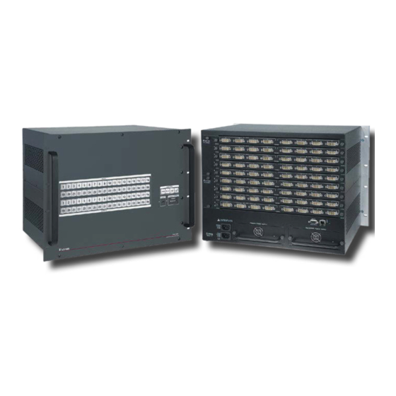
This guide contains installation, configuration, and operating information for the Extron figure 1 DMS 1600, DMS 2000, DMS 3200, and DMS 3600 Matrix Switchers (see on the next page). These customizable matrix switchers support DVI inputs and outputs and the fiber optic outputs and inputs of Extron DFX transmitters and receivers. - Page 9 9, you can expand and contract the DMS matrix as follows: DMS 1600 — Supports up to four I/O boards, up to a 16-input by 16-output matrix. DMS 2000 — Supports up to five I/O boards, up to a 20-input by 20-output matrix.
-
Page 10: Features
DSVP feature confirms that input sources are active by scanning all sync inputs for active signals. DSVP provides instantaneous feedback via any of the remote control ports on the switcher. DMS 1600, DMS 2000, DMS 3200, and DMS 3600 • Introduction... - Page 11 Two hot-swappable power supplies (standard for the DMS 3600 and optional • for the DMS 1600) — The 100 VAC to 240 VAC, 50-60 Hz power supplies of the matrix switchers provide worldwide power compatibility. Primary and redundant circuits — The power supply circuitry is configured to •...
- Page 12 I/O grouping limits the selection of inputs and outputs to members of the same group. I/O grouping allows specific outputs, such as those designated for a specific purpose, to be grouped together. DMS 1600, DMS 2000, DMS 3200, and DMS 3600 • Introduction...
-
Page 13: Installation
(optional). … Connect power (page 13). … Test the switcher by creating a tie (page 23). Ancillary operations … Install the Matrix Switchers Control Program (page 61). DMS 1600, DMS 2000, DMS 3200, and DMS 3600 • Installation... -
Page 14: Rear Panel Cabling And Features
Rear Panel Cabling and Features Figure 3, below, shows a DMS 1600. Figure 4, below, shows a DMS 2000. Figure 5, on the next page, shows a DMS 3200. Figure 6, on the next page, shows a DMS 3600. The four models have similar features, but different-sized enclosures and a different arrangement of the features.The DMS 2000 and DMS 3200 do not have swappable power supplies or fan... - Page 15 Fiber optic output connectors (see page Power connectors (see page Power indicator LEDs (DMS 1600 and DMS 3600 only) (see page Cooling fan assemblies (DMS 1600 and DMS 3600 only) (see page 106) DMS 1600, DMS 2000, DMS 3200, and DMS 3600 • Installation...
-
Page 16: I/O Boards
2 [location 5 - 8] are as follows: A = 5, B = 6, C = 7, and D = 8.) Inputs and outputs are grouped separately, with inputs A through D on the left and outputs A through D on the right. DMS 1600, DMS 2000, DMS 3200, and DMS 3600 • Installation... - Page 17 * CEC control on pin 8 is a proprietary usage, DDC data Ground (+5 V) TMDS clock+ not the industry CEC control* Hot Plug Detect TMDS clock– standard. Figure 8. DVI Connectors DMS 1600, DMS 2000, DMS 3200, and DMS 3600 • Installation...
-
Page 18: Remote Port
Ethernet LAN. This LED should light steadily. • Act LED indicator — Indicates transmission of data packets on the RJ-45 connector. This LED should flicker as the switcher communicates. DMS 1600, DMS 2000, DMS 3200, and DMS 3600 • Installation... -
Page 19: Reset Button And Led
In the event of a complete system reset, the passwords convert to the default, which is no password (see Passwords Page on page 92 to change the password). DMS 1600, DMS 2000, DMS 3200, and DMS 3600 • Installation... -
Page 20: Power
Redundant power connectors are present on the DMS 1600 and DMS 3600 only. • A redundant power supply is optional for the DMS 1600 and standard for the DMS 3600. • For the most reliable power with your DMS 1600 and DMS 3600, connect... -
Page 21: Operation
Background Illumination be turned off (see on page 35). The buttons blink or are lit at full intensity (depending on the operation) when selected. DMS 1600, DMS 2000, DMS 3200, and DMS 3600 • Operation... - Page 22 Esc button (see page Enter button (see page Power Supply indicators (DMS 1600 and DMS 3600) (see page Preset button (see page Power indicator (DMS 2000 DMS 3600) (see page DMS 1600, DMS 2000, DMS 3200, and DMS 3600 • Operation...
-
Page 23: Input And Output Buttons
Inputs shown above: Select configuration Configuration mode Action 2 Input defined Input defined NOTE : DMS 1600, 3200 — Input 15 (232) / 16 (422) at left: at left: DMS 2000 — Input 9 (232) / 10 (422) Select RS-232 Select RS-422 DMS 3600 —... - Page 24 Input 1 and Input 2 only — Toggle background illumination of the buttons on and off. Input 15 and 16 (DMS 1600 and DMS 3200), Input 9 and 10 (DMS 2000), or • Input 17 and 18 (DMS 3600) — Select Serial Port Selection and Configuration mode.
-
Page 25: Control Buttons
Selects 19200 baud for the RS-232/RS-422 port in Serial Port Selection and Configuration mode and indicates its selection. • With the View button, indicates that the front panel lock has been toggled on or off. DMS 1600, DMS 2000, DMS 3200, and DMS 3600 • Operation... -
Page 26: Power Indicators
(DMS 1600 and DMS 3600) on page 103 to replace the power supply). Unlit (DMS 1600 Redundant LED) — No power supply is installed. DMS 2000 and DMS 3200 Power LED — Indicates that the power supply is operating within normal POWER tolerances. -
Page 27: Button Labels
NOTE: The DMS 2000 and DMS 3200 each have a built-in, non-removeable power supply, which does not have the Power Supply LEDs ( A ), below. The primary and redundant power supply modules on the DMS 1600 and DMS 3600 (see figure 17) each have a 2-color LED. -
Page 28: Front Panel Operations
Room memory preset — A configuration consisting of outputs in a single room that has been stored. When a room preset is retrieved from memory, it becomes the current configuration. DMS 1600, DMS 2000, DMS 3200, and DMS 3600 • Operation... -
Page 29: Power
If you press the input button for an input that is I/O grouped I/O Grouping (see on page 27 ), you cannot select the output button for an output in a different group. The associated input button remains lit. DMS 1600, DMS 2000, DMS 3200, and DMS 3600 • Operation... - Page 30 The current configuration is now input 5 tied to output 3, output 4, and output 8 (see figure 18). Input 5 tied to outputs 3, 4, and 8 Input Output Figure 18. Example 1: Create Ties DMS 1600, DMS 2000, DMS 3200, and DMS 3600 • Operation...
- Page 31 The current configuration is now input 5 tied to output 1, output 3, output 4, and output 8 (see figure 19). Input 5 tied to outputs 1, 3, 4, and 8 Input Output Figure 19. Example 2: Add a Tie DMS 1600, DMS 2000, DMS 3200, and DMS 3600 • Operation...
- Page 32 The current configuration is now input 5 tied to output 1, output 3, and output 8 (see figure 20). Input 5 tied to outputs 1, 3, and 8 Input Output Figure 20. Example 3: Remove a Tie DMS 1600, DMS 2000, DMS 3200, and DMS 3600 • Operation...
-
Page 33: Viewing A Configuration
5 light. 8 15 16 OUTPUTS The output buttons for outputs that are not tied to Input 5 are either unlit or background illuminated. DMS 1600, DMS 2000, DMS 3200, and DMS 3600 • Operation... -
Page 34: I/O Grouping
2. Ungrouped inputs and outputs can be switched to outputs and inputs in any group. Ties between groups (an input in group 1 tied to an output in group 2) can be created under RS-232/RS-422 or Ethernet control. DMS 1600, DMS 2000, DMS 3200, and DMS 3600 • Operation... - Page 35 • For I/O groups to have any function, at least two groups must be created. DMS 1600, DMS 2000, DMS 3200, and DMS 3600 • Operation...
- Page 36 Select an I/O group: Press and release the Preset button to select group 2. Press the button. The button lights. C O N T R O L VIEW ENTER PRESET Group # DMS 1600, DMS 2000, DMS 3200, and DMS 3600 • Operation...
-
Page 37: Using Presets
The current configuration (configuration 0) can be saved as a preset in any one of 32 preset memory addresses. Presets can be saved and recalled from the front panel. • On the DMS 1600 and DMS 2000, the preset locations are assigned to both the input and output buttons (see figure 22). •... - Page 38 C O N T R O L ENTER PRESET VIEW All input buttons and output buttons return to unlit or The Enter and Preset background illumination. buttons return to unlit or background illumination. DMS 1600, DMS 2000, DMS 3200, and DMS 3600 • Operation...
- Page 39 C O N T R O L ENTER PRESET VIEW All input buttons and output buttons return to unlit or The Enter and Preset background illumination. buttons return to unlit or background illumination. DMS 1600, DMS 2000, DMS 3200, and DMS 3600 • Operation...
-
Page 40: Muting And Unmuting Outputs
2 seconds outputs are muted. NOTE: When you push Input 3, it lights and Input 4 returns to unlit because of ties made in examples 1, 2, and 3. DMS 1600, DMS 2000, DMS 3200, and DMS 3600 • Operation... -
Page 41: Locking The Front Panel (Executive Mode)
C O N T R O L buttons blink twice to indicate the mode 2 seconds ENTER PRESET VIEW ENTER PRESET VIEW change. Release the buttons. Figure 23. Locking the Front Panel DMS 1600, DMS 2000, DMS 3200, and DMS 3600 • Operation... -
Page 42: Performing A System Reset From The Front Panel
2 seconds (see figure 25). Press and hold the buttons. 3 16 After approximately 2 seconds, release the Input 1 and Input 2 buttons. Figure 25. Locking the Front Panel DMS 1600, DMS 2000, DMS 3200, and DMS 3600 • Operation... -
Page 43: Selecting The Rear Panel Remote Port Protocol And Baud Rate
For different reset levels, press and hold the button while the switcher is running or press and hold the button while you apply power to the switcher. See the table on the next page for a summary of the modes. DMS 1600, DMS 2000, DMS 3200, and DMS 3600 • Operation... - Page 44 In the The reset LED flashes three times in quick succession event of a complete system during the reset. reset, the passwords convert to the default, which is no password. DMS 1600, DMS 2000, DMS 3200, and DMS 3600 • Operation...
-
Page 45: Performing Soft System Resets (Modes 3, 4, And 5)
Absolute Reset 9 seconds RESET (Mode 5) View and Esc buttons flash three times. CONTROL ENTER PRESET VIEW Figure 26. Soft System Resets DMS 1600, DMS 2000, DMS 3200, and DMS 3600 • Operation... -
Page 46: Performing A Hard Reset (Mode 1)
Check the cabling and make corrections as necessary. Call the Extron Sales and Technical Support Hotline if necessary (see the contact • numbers listed on the Extron webpage for the office nearest you). DMS 1600, DMS 2000, DMS 3200, and DMS 3600 • Operation... -
Page 47: Digital Signal Guidelines
DVI or HDMI cables. Additional links in the signal chain can result in the reduction of signal integrity and overall cable length performance. DMS 1600, DMS 2000, DMS 3200, and DMS 3600 • Operation... -
Page 48: Configuration Worksheets
Output destinations Preset # Title: Fill in the preset number and use colors, or dashes, etc. to make connecting lines. Figure 28. Worksheet Example 1: System Equipment DMS 1600, DMS 2000, DMS 3200, and DMS 3600 • Operation... -
Page 49: Worksheet Example 2: Daily Configuration
Output destinations Preset # Title: Fill in the preset number and use colors, or dashes, etc. to make connecting lines. Figure 29. Worksheet Example 2: Daily Configuration DMS 1600, DMS 2000, DMS 3200, and DMS 3600 • Operation... -
Page 50: Worksheet Example 3: Test Configuration
Output destinations Preset # Title: Fill in the preset number and use colors, or dashes, etc. to make connecting lines. Figure 30. Worksheet Example 3: Test Configuration DMS 1600, DMS 2000, DMS 3200, and DMS 3600 • Operation... - Page 51 Input sources Output destinations Preset # Fill in the preset number and use colors, or dashes, etc. to make connecting lines. Blank Configuration Worksheet, DMS 1600...
- Page 52 Input sources Output destinations Preset # Fill in the preset number and use colors, or dashes, etc. to make connecting lines. Blank Configuration Worksheet, DMS 2000, DMS 3200, and DMS 3600...
-
Page 53: Programming Guide
8.0 or newer of the Matrix Switchers Control Program and then run the Found New Hardware Wizard (see Installing the Software page 61 and Activating a USB Port for the First Time on page 65). DMS 1600, DMS 2000, DMS 3200, and DMS 3600 • Programming Guide... -
Page 54: Ethernet (Lan) Port
Query (Q) command to keep the connection active. If there are long idle periods, Extron recommends disconnecting the socket and reopening the connection when another command must be sent. DMS 1600, DMS 2000, DMS 3200, and DMS 3600 • Programming Guide... -
Page 55: Number Of Connections
In the event of a complete system reset, the passwords convert to the default, which is no password (see Passwords Page on page 92 to change the password). DMS 1600, DMS 2000, DMS 3200, and DMS 3600 • Programming Guide... -
Page 56: Switcher Error Responses
Letters in the command field are not case-sensitive. The table below shows the hexadecimal equivalent of each ASCII character used in the command and response table. ASCII to Hex Conversion Table Space • DMS 1600, DMS 2000, DMS 3200, and DMS 3600 • Programming Guide... -
Page 57: Command And Response Table For Sis Commands
Positive or negative voltage and magnitude = Temperature Degrees Fahrenheit = Fan speed In revolutions per minute (RPM) = Power supply status 0 = not installed or failed 1 = installed and OK DMS 1600, DMS 2000, DMS 3200, and DMS 3600 • Programming Guide... - Page 58 This communication takes place over the Display Data Channel (DDC). • In the commands, the EDID data can come from either an active output or be set to a specified value. DMS 1600, DMS 2000, DMS 3200, and DMS 3600 • Programming Guide...
- Page 59 1080p @ 50 Hz 1080p @ 60 Hz, stereo * Default resolution and refresh rate 46 – 53 50 – 57 62 – 69 66 – 73 User defined DMS 1600, DMS 2000, DMS 3200, and DMS 3600 • Programming Guide...
- Page 60 01 through 10 (each can have up to 10 room presets [ s] assigned) = Name Up to 12 upper-and lower-case alphanumeric characters are valid = Room preset number 00 through 10 DMS 1600, DMS 2000, DMS 3200, and DMS 3600 • Programming Guide...
- Page 61 01 through 10 (each can have up to 10 room presets [ s] assigned) = Room preset number 01 through 10 = Connection status 0 = no input connected 1 = input connected DMS 1600, DMS 2000, DMS 3200, and DMS 3600 • Programming Guide...
- Page 62 00 through 10 = Name Up to 12 upper-and lower-case alphanumeric characters are valid = Group number (for I/O grouping) 1 through 4 (or 0 = no group) DMS 1600, DMS 2000, DMS 3200, and DMS 3600 • Programming Guide...
- Page 63 D3 = 0 fiber inputs x 4 outputs = Part number 60 -nnnn- 01 = Firmware version number to second decimal place (x.xx) X1& = Verbose firmware version-description-upload date/time DMS 1600, DMS 2000, DMS 3200, and DMS 3600 • Programming Guide...
- Page 64 = Voltage (positive or negative voltage and magnitude) = Temperature Degrees Fahrenheit = Fan speed In revolutions per minute (RPM) = Power supply status 0 = not installed or failed 1 = installed and OK DMS 1600, DMS 2000, DMS 3200, and DMS 3600 • Programming Guide...
- Page 65 ECN}, returns Ipn•X3)]). = Port timeout interval (in 10-sec. increments) 1 (= 10 seconds) – 65000 (default is 30 = 300 seconds = 5 minutes) DMS 1600, DMS 2000, DMS 3200, and DMS 3600 • Programming Guide...
- Page 66 Set e-mail recipient command), will receive fail/missing and fixed/restore messages for all inputs. EX4#X4! , X4$ EM } X4% , X4% , X4% ,..., X4%] Read e-mail events for recipients DMS 1600, DMS 2000, DMS 3200, and DMS 3600 • Programming Guide...
- Page 67 E 0TC } View current port timeout E 1* X5$ TC } Pti1* X5$] Configure global IP port timeout E 1TC } X5$] View global IP port timeout DMS 1600, DMS 2000, DMS 3200, and DMS 3600 • Programming Guide...
-
Page 68: Matrix Software
Selecting the Download Tab Click the link, as appropriate to the operation you are Software Firmware performing ( ). The main download page opens (see figure 32 on the next page). DMS 1600, DMS 2000, DMS 3200, and DMS 3600 • Matrix Software... - Page 69 5 5 5 5 5 5 5 5 4 4 4 4 4 4 4 4 2 2 2 2 2 2 2 2 Figure 33. Log in Dialog Box DMS 1600, DMS 2000, DMS 3200, and DMS 3600 • Matrix Software...
- Page 70 9600, 19200, 38400, or 115200 baud rate (see the parameters SIS commands on page 60 to configure the port). Front panel Configuration port — A USB B port. DMS 1600, DMS 2000, DMS 3200, and DMS 3600 • Matrix Software...
-
Page 71: Software Operation Via Ethernet
1 1 1 1 1 1 1 1 2 2 2 2 2 2 2 2 2 2 2 2 2 2 2 2 Figure 35. Found New Hardware Wizard DMS 1600, DMS 2000, DMS 3200, and DMS 3600 • Matrix Software... -
Page 72: Starting The Program
Click OK. The Extron Matrix Switchers Control Program window (see figure 38 figure 39 on page 67) opens, displaying the current configuration of the attached matrix. Proceed to Using the program on the next page. DMS 1600, DMS 2000, DMS 3200, and DMS 3600 • Matrix Software... -
Page 73: Using The Program
To make the control program easier to use, assign a device icon to each input and • output. Click on a box that represents an input or output, and drag the desired icon onto the box from the icon palette that opens. DMS 1600, DMS 2000, DMS 3200, and DMS 3600 • Matrix Software... - Page 74 (see the inset box in figure 39). You can print a map of the current configuration by clicking File > TIP: Print Tie Map DMS 1600, DMS 2000, DMS 3200, and DMS 3600 • Matrix Software...
-
Page 75: Ip Settings/Options Window
Administrator and User Password fields are not masked. If a password has been inadvertently changed to an unknown value, you can look up and, if desired, change a password in this window without knowing the current password. DMS 1600, DMS 2000, DMS 3200, and DMS 3600 • Matrix Software... - Page 76 IP address using Dynamic Host Configuration Protocol (DHCP) (if the network is DHCP capable). The default setting is off (deselected). Contact the local system administrator to determine whether to use DHCP. DMS 1600, DMS 2000, DMS 3200, and DMS 3600 • Matrix Software...
- Page 77 Set Daylight Saving NOTE: For Daylight Saving Time in Europe and Brazil, see the Time SIS command on page 59. DMS 1600, DMS 2000, DMS 3200, and DMS 3600 • Matrix Software...
- Page 78 Edit the case-sensitive password as desired. Press <Tab> on the keyboard or click in another field to exit the Password field. Click Take to make the password change take effect. DMS 1600, DMS 2000, DMS 3200, and DMS 3600 • Matrix Software...
- Page 79 If desired, click Send test E-mail to test the e-mail function. Click Take to make the e-mail address changes take effect. DMS 1600, DMS 2000, DMS 3200, and DMS 3600 • Matrix Software...
-
Page 80: Updating Firmware
1 1 1 1 1 1 1 1 Figure 43. Downloading Firmware Upgrade Files — Security Warning The InstallShield Wizard opens (see figure 44 on the next page). DMS 1600, DMS 2000, DMS 3200, and DMS 3600 • Matrix Software... - Page 81 If you are connected via either serial port, the Firmware Loader window opens (see figure 46 and Serial-port or USB-port-connected firmware upload page 76). DMS 1600, DMS 2000, DMS 3200, and DMS 3600 • Matrix Software...
- Page 82 DMS 1600, DMS 2000, DMS 3200, and DMS 3600 • Matrix Software...
- Page 83 Once the status bars have progressed from 0% to 100%, and Status is listed as Complete, the firmware loader utility resets the switcher. Figure 48. Firmware Loader Screen Click Exit to close the Firmware Loader. DMS 1600, DMS 2000, DMS 3200, and DMS 3600 • Matrix Software...
-
Page 84: Uploading Html Files
Click Open. The upload of files to the DMS matrix switcher may take a few minutes. Click Update to confirm the upload ( Click Close to exit the HTML Files List window ( DMS 1600, DMS 2000, DMS 3200, and DMS 3600 • Matrix Software... -
Page 85: Windows Buttons, Drop Boxes, And Trash Can
Select printer — Selects the target printer. Print tie map — Prints the tie set that is displayed on the screen. Exit — Closes the Matrix Switchers Control Program. DMS 1600, DMS 2000, DMS 3200, and DMS 3600 • Matrix Software... - Page 86 (see Updating Firmware on page 73). IP Options — Allows you to set IP options (see IP Settings/Options Window page 68). DMS 1600, DMS 2000, DMS 3200, and DMS 3600 • Matrix Software...
- Page 87 Out Channels field can be helpful in identifying a specific input or output. In figure 52, for example, output 29 is identified as slot 8, connector A (8o01). Figure 52. Physical Configuration Dialog Box DMS 1600, DMS 2000, DMS 3200, and DMS 3600 • Matrix Software...
- Page 88 Ties that will take effect when you click Take are indicated by +. Ties that will be broken when you click Take are indicated by –. Figure 53. Ties Shown as Crosspoints DMS 1600, DMS 2000, DMS 3200, and DMS 3600 • Matrix Software...
-
Page 89: Using Emulation Mode
(4x4), input only (4x0), or output only (0x4), for each board. Click OK. Continue using the program as described on page Figure 54. Emulation Mode Configuration DMS 1600, DMS 2000, DMS 3200, and DMS 3600 • Matrix Software... -
Page 90: Using The Help System
ButtonLabelGenerator directory and places the Button Label Generator icon into a group or folder named “Extron Electronics.” NOTE: For Windows 7 and newer, the folder is C:\Program Files (x86)\Extron\ ButtonLabelGenerator. DMS 1600, DMS 2000, DMS 3200, and DMS 3600 • Matrix Software... -
Page 91: Using The Button Label Generator Software
Click Clear All Buttons and create new labels as many times as necessary to make all of the button labels that you need. To access the help program, click the Help menu. DMS 1600, DMS 2000, DMS 3200, and DMS 3600 • Matrix Software... -
Page 92: Html Operation
HTML Operation This section describes the operation of the DMS 1600 and DMS 3600 via their embedded web pages, including: • Opening the Embedded Web Pages • Status Tab Configuration Tab • • File Management Tab Control Tab • •... - Page 93 If neither of the above conditions is true, the switcher downloads the factory- installed default startup page, “nortxe_index.html”, also known as the System Status page (see figure 57, on the next page). DMS 1600, DMS 2000, DMS 3200, and DMS 3600 • HTML Operation...
-
Page 94: Status Tab
The System Status page periodically updates itself to reflect the latest status of the switcher components. If a variable changes, the display shows the change the next time it updates. DMS 1600, DMS 2000, DMS 3200, and DMS 3600 • HTML Operation... -
Page 95: Dsvp And Physical Configuration Page
Configuration link to the left of the Status page to download the DSVP and Physical Configuration page. The page updates every 30 seconds to show the latest board types and signal status. Figure 58. DSVP and Physical Configuration Page DMS 1600, DMS 2000, DMS 3200, and DMS 3600 • HTML Operation... -
Page 96: Configuration Tab
NOTE: The following characters are invalid or not recommend in the matrix name: + ~ , @ = ‘ [ ] { } < > ’ “ ; : | \ and ?. DMS 1600, DMS 2000, DMS 3200, and DMS 3600 • HTML Operation... - Page 97 Part Number field The Part Number field identifies the part number of your switcher. This field is hardcoded in the switcher and cannot be changed. DMS 1600, DMS 2000, DMS 3200, and DMS 3600 • HTML Operation...
- Page 98 When Daylight Saving Time is turned off, the switcher does not adjust its time reference. Click Submit. DMS 1600, DMS 2000, DMS 3200, and DMS 3600 • HTML Operation...
-
Page 99: Passwords Page
NOTE: An administrator password must be created before a user password can be created. To clear an existing password so that no password is required, enter a single space character in the Password and Re-enter Password fields, and click Submit. DMS 1600, DMS 2000, DMS 3200, and DMS 3600 • HTML Operation... -
Page 100: Email Settings Page
NOTE: The following characters are invalid or not recommended in a domain name: {space} @ + ~ , = ‘ [ ] { } < > ’ “ ; : | \ and ?. DMS 1600, DMS 2000, DMS 3200, and DMS 3600 • HTML Operation... -
Page 101: Firmware Upgrade Page
NOTE: Note the folder to which the firmware file is saved. Connect the PC to the DMS matrix switcher via the LAN port on the switcher. Access the DMS matrix switcher using HTML pages. Click the Configuration tab. DMS 1600, DMS 2000, DMS 3200, and DMS 3600 • HTML Operation... - Page 102 If the attempted firmware upload fails for any reason, the switcher automatically reverts to the factory-installed firmware. Click Open. Click Upload ( ). The firmware upload to the DMS matrix switcher may take a few minutes. DMS 1600, DMS 2000, DMS 3200, and DMS 3600 • HTML Operation...
-
Page 103: File Management Tab
NOTE: If you want one of the pages that you create and upload to be the default startup page, name that file “index.html.” Click Upload File ( ). The files that you selected appear in the list. DMS 1600, DMS 2000, DMS 3200, and DMS 3600 • HTML Operation... -
Page 104: Control Tab
To tie an input to all outputs, click the input number for that input. Click Take ( ) to make the configuration changes or Cancel to abandon the configuration changes. DMS 1600, DMS 2000, DMS 3200, and DMS 3600 • HTML Operation... -
Page 105: Edid And Mute Settings Page
Save the output resolution of the monitor connected to output 1 to one of the User Assigned locations by clicking the desired User button. Toggle mute on and off for an output by clicking the Mute button for that output. DMS 1600, DMS 2000, DMS 3200, and DMS 3600 • HTML Operation... -
Page 106: Special Characters
Use of the following characters is not recommended: {space} + ~ , @ = ‘ [ ] { } < > ’ “ semicolon (;) colon (:) | \ and ?. DMS 1600, DMS 2000, DMS 3200, and DMS 3600 • HTML Operation... -
Page 107: Maintenance And Modifications
• Mounting the Switcher The DMS 1600 is housed in a rack-mountable, 4U high metal enclosure with mounting flanges for standard 19-inch racks. The DMS 2000 is in a 3U high enclosure. The DMS 3200 is in a 5U high enclosure. The DMS 3600 is in an 8U high enclosure. -
Page 108: Removing And Installing The I/O Board Or Blank Panel
4-output), you can follow a DVI board with a fiber optic board or follow a fiber optic board with a DVI board. If you install a blank panel, all slots under it must contain blank panels (you cannot skip • a slot). DMS 1600, DMS 2000, DMS 3200, and DMS 3600 • Maintenance and Modifications... -
Page 109: Removing The I/O Board Or Blank Panel
Connectors 0- 24 /6 0H 1. 2A Knurled Knobs Figure 69. I/O Board Replacement Place the removed board on an antistatic surface or in an antistatic container. DMS 1600, DMS 2000, DMS 3200, and DMS 3600 • Maintenance and Modifications... -
Page 110: Installing The I/O Board Or Blank Panel
The DMS matrix switchers use double pole/neutral fusing. Power must be disconnected before servicing internal components. Le DMS utilise un système de fusible neutre/à double pôle. L’alimentation doit être • déconnectée avant tout entretien de composants internes. DMS 1600, DMS 2000, DMS 3200, and DMS 3600 • Maintenance and Modifications... -
Page 111: Removing The Power Supply Module
Gently slide the power supply module into the enclosure until the power supply meets resistance. Gently seat the power supply in the backplane. Use a screwdriver to tighten the left and right screws to lock the power supply in place. DMS 1600, DMS 2000, DMS 3200, and DMS 3600 • Maintenance and Modifications... -
Page 112: Removing And Installing A Fan Module (Dms 1600 And Dms 3600)
NOTE: The fan modules are hot-swappable and can be removed or installed without powering down the switcher. The DMS 1600 has a single fan module. The DMS 3600 has two identical fan modules. If a fan fails, it should be replaced at the earliest opportunity. -
Page 113: Removing And Installing Button Labels
Gently, but firmly, press the reassembled button into place in the front panel of the switcher. Repeat steps 1 to 7 as needed to relabel other buttons. DMS 1600, DMS 2000, DMS 3200, and DMS 3600 • Maintenance and Modifications... - Page 114 DMS 1600, DMS 2000, DMS 3200, and DMS 3600 • Maintenance and Modifications...
-
Page 115: Ethernet Connection
IP address using the ping utility. If the address has not been changed, the factory-specified default is 192.168.254.254. Ping can also be used to test the Ethernet link to the DMS matrix switcher. DMS 1600, DMS 2000, DMS 3200, and DMS 3600 • Ethernet Connection... -
Page 116: Pinging To Determine The Extron Ip Address
Obtain a valid IP address for the DMS matrix switcher from your network administrator. Obtain the MAC address (UID #) of the DMS matrix switcher from the label on its rear panel. The MAC address should have this format: 00-05-A6-xx-xx-xx. DMS 1600, DMS 2000, DMS 3200, and DMS 3600 • Ethernet Connection... - Page 117 After verifying that the IP address change was successful, enter and issue the arp –d command at the DOS prompt. For example: arp –d 192.168.254.254 removes 192.168.254.254 from the ARP table arp –d* removes all static IP addresses from the ARP table. DMS 1600, DMS 2000, DMS 3200, and DMS 3600 • Ethernet Connection...
-
Page 118: Connecting As A Telnet Client
Users can create ties, set mutes, and view all settings with the exception of passwords. By default, the DMS matrix switcher ships with both passwords set to the device serial number. DMS 1600, DMS 2000, DMS 3200, and DMS 3600 • Ethernet Connection... - Page 119 Exit the Telnet utility by typing quit and then pressing <Enter> at the Telnet prompt. If you are connected to the DMS matrix switcher, access the Telnet prompt by typing the Escape character (<Ctrl>+<]>). DMS 1600, DMS 2000, DMS 3200, and DMS 3600 • Ethernet Connection...
-
Page 120: Subnetting - A Primer
0 indicates that this octet will not be compared between two IP addresses. compared between two IP addresses. Typical Subnet Mask: 255.255.0.0 Octets Figure 79. Typical Subnet Mask DMS 1600, DMS 2000, DMS 3200, and DMS 3600 • Ethernet Connection... -
Page 121: Determining Whether Devices Are On The Same Subnet
— Match ≠.≠.X.X — No match =.≠.X.X — No match subnet) subnet) subnet) (Same (Different (Different Figure 80. Comparing the IP Addresses of the Local and Remote Devices DMS 1600, DMS 2000, DMS 3200, and DMS 3600 • Ethernet Connection... - Page 122 Extron Electronics makes no further warranties either expressed or implied with respect to the product and its quality, performance, merchantability, or fitness for any particular use. In no event will Extron Electronics be liable for direct, indirect, or consequential damages resulting from any defect in this product even if Extron Electronics has been advised of such damage.
Need help?
Do you have a question about the DMS 1600 and is the answer not in the manual?
Questions and answers