Extron electronics Cable Cubby 200 User Manual
Surface access products for cables, aaps, and power outlets
Hide thumbs
Also See for Cable Cubby 200:
- User manual (18 pages) ,
- User manual (62 pages) ,
- User manual (3 pages)
Table of Contents
Advertisement
Quick Links
Extron Electronics, USA
Extron Electronics, Europe
1230 South Lewis Street
Beeldschermweg 6C
Anaheim, CA 92805
3821 AH Amersfoort
USA
The Netherlands
714.491.1500
+31.33.453.4040
www.extron.com
Fax 714.491.1517
Fax +31.33.453.4050
© 2006 Extron Electronics. All rights reserved.
Extron Electronics, Asia
Extron Electronics, Japan
135 Joo Seng Road, #04-01
Kyodo Building
PM Industrial Building
16 Ichibancho
Singapore 368363
Chiyoda-ku, Tokyo 102-0082 Japan
+65.6383.4400
+81.3.3511.7655
Fax +65.6383.4664
Fax +81.3.3511.7656
User's Manual
Surface Access Products for Cables, AAPs, and Power Outlets
Cable Cubby
®
200
Cable Cubby
®
300C
Cable Cubby
®
300S
Cable Cubby
®
600
Cable Cubby
®
800
68-701-01 Rev. F
06 06
Advertisement
Table of Contents

Related Manuals for Extron electronics Cable Cubby 200


Summary of Contents for Extron electronics Cable Cubby 200
- Page 1 Extron Electronics, USA Extron Electronics, Europe Extron Electronics, Asia 1230 South Lewis Street Beeldschermweg 6C 135 Joo Seng Road, #04-01 Anaheim, CA 92805 3821 AH Amersfoort PM Industrial Building The Netherlands Singapore 368363 714.491.1500 +31.33.453.4040 +65.6383.4400 www.extron.com Fax 714.491.1517 Fax +31.33.453.4050 Fax +65.6383.4664 ©...
-
Page 3: Table Of Contents
Table of Contents Chapter One • Introduction ... 1-1 About the Cable Cubby ® Products Features ... 1-5 Chapter Two • Installation ... 2-1 Installation Overview ... 2-2 Preparing the Routing Template ... 2-3 Preparing the Table ... 2-4 Preparing the table with a router ... 2-4 Preparing the table with a hole saw (Cable Cubby 300C only) ... -
Page 4: Chapter One • Introduction
Table of Contents, cont’d ® Cable Cubby Products Chapter One Introduction About the Cable Cubby ® Products Features 68-701-01 Rev. F 06 06 All trademarks mentioned in this manual are the properties of their respective owners. Cable Cubby ® Products • Table of Contents... -
Page 5: About The Cable Cubby Products
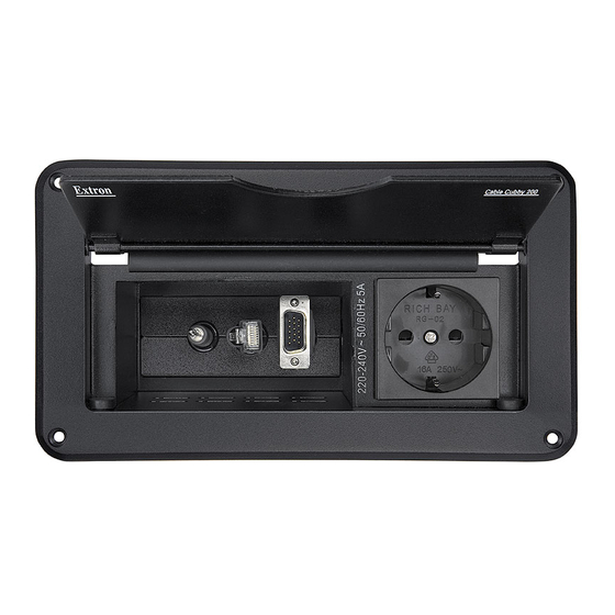
AAPs and the power outlets are adjustable to suit cable lengths and connector types. The elevation and arrangement of the power outlet and AAPs in the Cable Cubby 200 are fi xed and not customizable. Cable Cubby ®... -
Page 6: Features
Introduction, cont’d The installed Cable Cubbies fi t nearly fl ush within a table or podium top, storing the AAPs and cables out of the way and out of sight. To access the AAPs and connectors, lift the lid (fi gure 1-2). Half-moon cutouts in the lid allow you to run cables in or out and then close the lid. -
Page 7: Preparing The Routing Template
Introduction, cont’d ® Cable Cubby Products Chapter Two Installation Installation Overview Preparing the Routing Template Preparing the Table Installing the Cables and AAPs Mounting the Cable Cubby ® Cable Cubby Products • Introduction... -
Page 8: Installation Overview
Installation Installation Overview Install and set up the Cable Cubby enclosures as follows: If you plan to use a mounting template that has not been prepared, prepare the template. See Preparing the Routing Template, later in this chapter. Cut a hole in the surface where the enclosure will be installed. -
Page 9: Preparing The Table
Installation, cont’d Preparing the Table The preferred and recommended method for preparing the table for square Cable Cubbies and one of two preferred methods for the Cable Cubby 300C is to use the appropriate Extron routing template and a router. For the Cable Cubby 300C, another preferred method is to use a 6"... -
Page 10: Preparing The Table With A Hole Saw (Cable Cubby 300C Only)
Installing the Cables and AAPs Each Cable Cubby 300, 600, and 800 model ships with one or two moveable AAP shelf assemblies. The Cable Cubby 200’s AAP shelf is fi xed in place. AAP shelf brackets (CC 300, 600, 800) Each shipped AAP shelf assembly consists of a set of shelf brackets and a number of cable pass-through (split) AAPs. -
Page 11: Installing The Power Module (Cc 300, 600, 800)
Installation, cont’d Installing the power module (CC 300, 600, 800) From the underside of the Cable Cubby, gently push the power module into the desired position at the desired elevation. Secure the power module into position with four Phillips head screws. Installing the cables Three half-moon cutouts in each set of cable pass-through (split) AAPs loosely channel three cables in the cubby. -
Page 12: Installing The Shelf Assembly (Cc 300, 600, 800)
AAP mounting nuts once the AAP shelf assembly is installed in position. Adjusting the cable position (CC 200) The Cable Cubby 200 has three cable stand-offs (fi gure 2-6) that allow you to set the height of the cables inside the enclosure. Adjust the cable height as follows:... - Page 13 Cable Cubby 200 — Drill 1/8" (3 mm) pilot holes ½" (12 mm) deep into the table in the mounting holes at each of the four corners of the cubby.
-
Page 14: Chapter 3 • Maintenance And Modifi Cations
Installation, cont’d ® Cable Cubby Products C hapter 3 Maintenance and Modifi cations Removing and Replacing the Cable Cubby Replacing Cables or an AAP Adding an Additional Power Module (CC 600, CC 800) ® 2-14 Cable Cubby Products • Installation... -
Page 15: Removing And Replacing The Cable Cubby
AAP shelf assembly and power module. The Cable Cubby 200 is screwed to the top surface of the table. Its shelves are fi xed in position and not removable. Remove and replace the Cable Cubby for maintenance as... -
Page 16: Replacing Cables Or An Aap
Maintenance and Modifi cations, cont’d Cable Cubby 200 — Remove the screws at the four corners that secure the cubby to the table (fi gure 3-2). Figure 3-2 — Removing the Cable Cubby 200 Lift the enclosure from the table. -
Page 17: Adding An Additional Power Module (Cc 600 And Cc 800)
Extron, and may be required to maximize the remaining available space if you add a power module. • Cable Cubby 200 models — Adding a second power module is not possible. • Cable Cubby 300 models — Adding a second power module is not recommended. - Page 18 Maintenance and Modifi cations, cont’d • Cable Cubby 600 and 800 US/Domestic models — You probably do need replacement shelf brackets when you add a US/Domestic power module to a US/Domestic Cable Cubby, because the power module takes up two spaces in a cubby that, in its standard confi...
-
Page 19: Cable Cubby Part Numbers
Maintenance and Modifi cations, cont’d From the underside of the Cable Cubby, gently push the additional power module into the desired position at the desired elevation. Secure the power module into position with the included four Phillips head screws (fi gure 3-7). Extron Cable Cubby 600 2 Screws ea. -
Page 20: Reference Information
AAPs are optional accessories for the Cable Cubby products. AAPs and cables must be ordered separately. Cable Cubby 200 Cable Cubby 200 Top plate (outer rim) ... 8.000" W x 4.394" D (20.32 cm W x 11.16 cm D) - Page 21 Small cable hole ... 0.50" (1.27 cm) Small grommet ... 0.31" (0.79 cm) Product weight Cable Cubby 200 ... 2.5 lbs (1.1 kg) Cable Cubby 300S/300C .. 5.0 lbs (2.3 kg) Cable Cubby 600... 9.0 lbs (4.1 kg) Cable Cubby 800... 13.0 lbs (5.9 kg) Cable Cubby ®...
-
Page 22: Cable Cubby Part Numbers
Specify the desired power connector and fi nish when ordering. All Cable Cubby 200 models are available in a powder coat fi nsh only. The USA versions of the Cable Cubby 300, 600, and 800 are also available in brushed aluminum, polished aluminum, and brushed brass fi... -
Page 23: Included Parts
Packaging for Shipment, cont’d Included Parts The Cable Cubby includes the Cable Cubby manual and a selection of shelf brackets, cable pass through AAPs, grommets, and hole plugs that vary depending on the Cable Cubby model. See the table below for included parts: Large Small Medium... -
Page 24: Routing Template Part Numbers
The following reuseable sheet metal routing templates are recommended for installation and are available at no charge. Template Part number Cable Cubby 200 routing template Cable Cubby 300S/300C routing template Cable Cubby 600 routing template Cable Cubby 800 routing template... - Page 25 (18.25 0.083 cm) 0.5" (1.3 cm) Cut-Out Radius: Cut surface material 0.25" out along this line. (0.6 cm) Figure A-4 — Cable Cubby 200 cut-out template ® A-12 Cable Cubby Products • Packaging for Shipment 8.00 (20.32 Top Panel Cut-Out Template for Extron's Cable Cubby 300S 5.130"...
- Page 26 Packaging for Shipment, cont’d Cut-Out Template for Extron's Cable Cubby 300C SURFACE CUT-OUT AREA = 6.000 0.0325" Dia. (15.24 0.083cm) User Access TEMPLATE IS NOT FULL SIZE. Figure A-6 — Cable Cubby 300C cut-out template ® A-14 Cable Cubby Products • Packaging for Shipment Cut-Out Template for Extron's Cable Cubby 600 6.960"...
-
Page 27: Appendix B • Packaging For Shipment
Packaging for Shipment, cont’d Cut-Out Template for Extron's Cable Cubby 800 8.360" (21.23 cm) 6.820" 6.320 0.0325" (17.32 cm) (16.05 0.083 cm) SURFACE CUT-OUT AREA = 7.860 0.0325 "( 19.96 0.083 cm) x 6.320 0.0325"(16.05 0.083 cm) Cut surface material Top Panel out along this line. - Page 28 Install the plastic strips that protect the fl anged edges of the top of the surface enclosure (fi gure B-2). Figure B-2 — Installing protective strips For Cable Cubby 200 models proceed to step 13. For Cable Cubby 300, 600, and 800 models, continue to step 4, below.
- Page 29 Packaging for Shipment, cont’d Figure B-3 — Removing center foam CC 600, 800 only — Remove and discard the inner side foam sections of the cushion in the carton (fi gure B-4). If you are returning a Cable Cubby 600 model, this is the correct fi...
- Page 30 (fi gure B-7). Figure B-7 — Placing the cubby in the carton CC 200 only — Insert the Cable Cubby 200 into the foam shell (fi gure B-8). Firmly push the Cable Cubby into the foam shell to completely suspend the Cable Cubby.
- Page 31 Packaging for Shipment, cont’d ® Cable Cubby Products • Packaging for Shipment Cable Cubby ® Products • Packaging for Shipment...
- Page 32 Packaging for Shipment ® B-10 Cable Cubby Products • Packaging for Shipment...
- Page 33 Precautions Safety Instructions • English Warning Power sources • This equipment should be operated only from the power source This symbol is intended to alert the user of important indicated on the product. This equipment is intended to be used with a main power operating and maintenance (servicing) instructions in system with a grounded (neutral) conductor.
Need help?
Do you have a question about the Cable Cubby 200 and is the answer not in the manual?
Questions and answers