Table of Contents
Advertisement
Quick Links
TLCA 1 Adapter • Setup Guide
Overview
The TLCA 1 is a TouchLink Control Port Expansion Adapter that provides multiple
control port options including an IR port, Digital Input port, two Communication
ports, and two Relay ports; transforming your wall mount, tabletop, and Cable
Cubby TouchLink Pro touchpanels into a powerful, all-in-one control system. This
innovative tool adds flexibility and power to our latest TouchLink Pro touchpanels,
including the TLP Pro 525 Series, TLP Pro 725 Series, TLP Pro 1025 Series and
TLP Pro 300M.
NOTE:
The TouchLink Pro touchpanel must have a LinkLicense for TLP Control
Processor, purchased separately and applied via Toolbelt, prior to using TLCA 1.
What is Included
1
Figure 1.
USB adapter and Mounting Clip
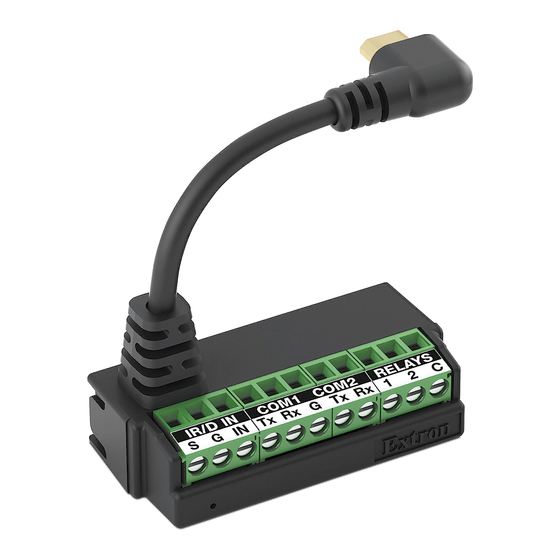
TLCA 1 Features
A
Ir/D IN
S
G
B c
Figure 2.
TLCA 1 Adapter — Top View
USB connector —
A
•
Insert the micro B connector into the micro B port of the 525M, 725M, 1025M and 300M wall mount models, or
•
Use the included USB adapter (see
and 725C Cable Cubby models.
IR Output port (shares the ground pin with Digital Input)
B
Digital Input port (shares the ground pin with IR port)
C
3-pole COM ports (two, with shared ground wire)
D
Relay Ports (two, with shared common wire)
E
Power LED indicator — provides the power status of the adapter
F
2
COM1
COM2
RELAY
IN
Tx
Rx
G
Tx
Rx
1
2
C
D
E
figure
1,
1
USB adapter — micro B to USB A connector.
1
Mounting Clip — for tabletop and Cable Cubby
2
installations. Includes four #6 screws.
F
Figure 3.
TLCA 1 Adapter — Front View
) for TLCA 1 use on 525T, 725T and 1025T table top models, or 525C
s
1
Advertisement
Table of Contents

Related Manuals for Extron electronics TLCA 1


Summary of Contents for Extron electronics TLCA 1
- Page 1 • Use the included USB adapter (see figure ) for TLCA 1 use on 525T, 725T and 1025T table top models, or 525C and 725C Cable Cubby models. IR Output port (shares the ground pin with Digital Input) Digital Input port (shares the ground pin with IR port)
- Page 2 TLCA 1 Adapter • Setup Guide (Continued) Control Ports Insert the wires from an IR Emitter into the IR port and place the head of the emitter over or next to the IR signal pickup window of the device being controlled.
- Page 3 NOTE: The maximum distance from the touchpanel to the device being controlled is usually 200 feet (61 m), but this can vary, depending on factors such as cable gauge, baud rates, environment, and output levels from the touchpanel and the device being controlled.
- Page 4 Adapter Installation Attaching the TLCA 1 to the Mounting Clip figure Insert the TLCA 1 into the mounting clip at an angle, captive-screw side first (see ), then the back side ( Figure 11. Attaching TLCA 1 to the Mounting Clip...
- Page 5 Mounting Under a Desk (for Tabletop TLP) To mount the TLCA 1 Adapter under a desk or other furniture, hold the mounting clip against the underside of the furniture. Mark the location of the mounting clip screw holes on the mounting surface.
- Page 6 ) is optimally positioned for connecting the TLCA 1 to the Cable Cubby. If the mounting position is flipped 180°, the TLCA 1 micro B cable may not reach the Cable Cubby USB output ( Plug the micro B connector, with the included USB adapter (...
Need help?
Do you have a question about the TLCA 1 and is the answer not in the manual?
Questions and answers