
Related Manuals for Recognition Systems HANDKEY II

Summary of Contents for Recognition Systems HANDKEY II
- Page 1 HandKey II Manual 1520 Dell Ave. Campbell, CA 95008 Technical Operations: 408-341-4110 RSI Main: 408-341-4100 RSI Main Fax: 408-341-4101 Web: www.handreader.com P/N: 70100-6001 Version 3.0...
- Page 2 This equipment has been tested and found to comply with the limits for a Class B digital device, pursuant to part 15 of the FCC Rules. These limits are designed to provide reasonable protection against harmful interference when the equipment is operated in a commercial environment. This equipment generates, uses, and can radiate radio frequency energy, and, if not installed and used in accordance with the Installation Manual, may cause harmful interference to radio communications.
-
Page 3: Table Of Contents
Table of Contents Introduction 4 Biometrics 4 Principle of Operation 4 Specifications 7 Planning an Installation 10 Site Preparation 10 HandReader Placement 10 Wiring 11 Power Input 11 Battery Backup 11 Earth Ground and Shielding 12 Door Control Output 15 Lock Output Mode 16 Card Reader Emulation Mode 16 Inputs and Outputs 16... - Page 4 Appendix B - Differences in Board Layouts 74 Appendix C - Old Board Configuration Information78 Appendix D - Troubleshooting 94 Glossary 96 Limited Warranty 98...
-
Page 5: Introduction
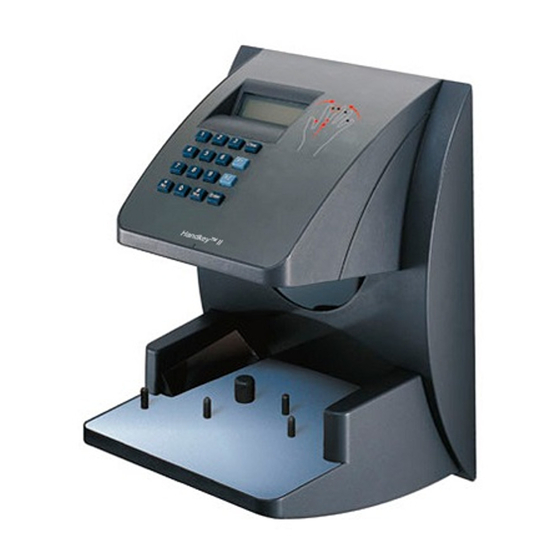
Refer to Figure 1-1 when reviewing the information in this section. 1. For the sake of using a consistent name throughout the manual, the HandKey II is referred to as the HandReader for the remainder of this manual. - Page 6 FUNCTION KEYS PLATEN AND GUIDE PINS Figure 1-1: The HandKey II The HandReader has an integrated keypad for ID entry and reader programming. It has two function keys (F1 and F2) that can be set to activate external devices CLEAR ENTER such as a doorbell or an automatic door.
- Page 7 HandKey II Manual 3. “Red light/green light” verification LEDs quickly inform users if their verification attempts were accepted or rejected. 4. An internal beeper provides audible feedback during keypad data entry and user verification. Page 5...
-
Page 8: Specifications
Introduction Specifications Table 1: Specifications Size: 8.85 inches wide by 11.65 inches high by 8.55 inches deep (22.3 cm) 22.3 cm wide by 29.6 cm high by 21.7 cm deep Power: 12 to 24 VDC or 12 to 24 VAC 50-60 Hz, 7 watts Weight: 6 lbs (2.7 kg) Wiring:... - Page 9 HandKey II Manual Table 1: Specifications Auxiliary Inputs Auxiliary Input 1 and 2 (open collector, 5 VDC present, sinks to ground, 100 mA max) Options HandKey units have the following options available. • Backup Battery Support See Technical Note 70200-0012 – Rev. E •...
- Page 10 Systems under the following conditions: 1. The HandKey II is configured at the factory with a Wiegand output that enables the HandKey II to communicate with an access control panel. The access control panel controls the locking and unlocking of the door. The panel must reside on the secure side of the facility.
-
Page 11: Planning An Installation
HandKey II Manual Planning an Installation Site Before you begin installation, check the site blueprints, riser diagrams, and Preparation specifications for important information about the HandRreader’s location and other systems that will connect to the HandReader. Look for any existing wall preparations and wiring that other contractors may have installed for the HandReaders. -
Page 12: Wiring
Planning an Installation Wiring Four basic circuits typically connect to the HandReader: • Power Input • Door Control Inputs and Outputs • Networking and Communications • Card Reader Input and Emulation Output Power Input The HandReader requires 12 to 24 volts DC (600 mA) or 12 to 24 volts AC (7 watts). -
Page 13: Earth Ground And Shielding
HandKey II Manual general two hours of battery operation can be expected. While operating on battery backup due to loss of main input power, the battery output voltage is constantly monitored by internal circuitry. If the battery voltage reaches approximately 9.5 volts the HandReader automatically shuts down. This is done to prevent full exhaustion of the battery. - Page 14 Planning an Installation The subject of grounding can be complicated, and the full circuit of a system, including power supplies and often even the building line power wiring, must be understood. It is strongly recommended that a qualified electrician or electrical engineer familiar with this subject be consulted when designing the wiring of an HGU network installation.
- Page 15 HandKey II Manual Earth Ground One method of establishing a ground reference is to connect each unit’s main All Units board ground to earth ground. Earth ground is found on the third pin on standard AC line sockets (in the United States, this is the round one in the middle).
-
Page 16: Door Control Output
Planning an Installation line in the RS-232 port from the host PC system. It should then be carried to one of the ground terminals on the back of each unit in the network. An example of this method of grounding is shown in Figure 2-4. Master Remote 1 Remote 2... -
Page 17: Lock Output Mode
HandKey II Manual Lock Output In the lock output mode, the HandReader acts as an intelligent access reader Mode signaling a lock relay or controller to unlock the door. It also monitors the status of the door. The decision to unlock the door is made by the HandReader after a valid verification. - Page 18 Planning an Installation HandReader outputs, when measured to ground, generally show around 4.5 volts when they are inactive and no load is attached. This voltage is developed by a combination diode and series resistor pull up to the internal +5 volt supply of the HandReader.
-
Page 19: Networking And Communications
HandKey II Manual Networking and Communications HandReader networking and communications can be configured in one of five ways: • as a stand-alone HandReader • as a master or remote HandReader in a HandReader network • as a remote HandReader in a HandReader network connected to a host PC •... -
Page 20: Remote Handreader Connected To A Host Pc Via Optional Modem
Networking and Communications • An unlimited number of sites can be created with up to 32 HandReaders per site. • The HandReaders report all transactions to the PC. The HandNet software records all transactions and displays a variety of reports generated from this information. -
Page 21: Remote Handreader Connected To A Host Pc Via Optional Ethernet
HandKey II Manual Remote The HandReader is available with an optional, internal Ethernet communications HandReader module for TCP/IP communications. The wiring must conform to 10BaseT Connected to standards. Typically, network wiring terminates at the HandReader with a a Host PC via standard RJ-45 modular jack. - Page 22 Networking and Communications This page is intentionally blank. Page 20...
-
Page 23: Mechanical Installation
HandKey II Manual Mechanical Installation Select an installation location based on the guidelines provided in the Planning an Installation section beginning on page 9. Wall Plate Installation For the following instructions protect the HandReader from the dust and debris NOTE generated during the wall plate installation process. -
Page 24: Mounting The Wall Plate
Mechanical Installation 5. Align a bubble level with the top edge of the wall plate and gently rotate the wall plate until the bubble level shows that the top edge of the wall plate is level. 6. Secure the plate to the wall using heavy masking tape. 7. - Page 25 HandKey II Manual HOLE 2 UPPER SCREWS SURFACE CONDUIT ENTRY REAR OF TERMINAL Figure 4-2: Attaching the HandReader to the Wall Plate 3. The HandReader is now ready for its wiring connections. Closing the With the wall mount latch in the unlocked position, swing the body of the HandReader HandReader up and rotate the key away from the wall.
- Page 26 Mechanical Installation W a l l P l a t e L a t c h K e y U n l o c k e d P o s i t i o n LOCK W a l l P l a t e L a t c h K e y L o c k e d P o s i t i o n...
-
Page 27: Wiring Connections
HandKey II Manual Wiring Connections Once the HandReader is attached to the wall plate the wiring connections to the HandReader can be made (see Figure 5-1). J7 Battery Reset WALL Wall Plate Jumper Switch Power Top of Terminal Optional Modem... - Page 28 Wiring Connections • Figure 5-8 on page 34 provides a typical Printer to HandReader wiring diagram. Table 2: TS-1 - Power and Communication Connections Terminal Connection RS-422 Rx- or RS-485 Rx-/Tx- RS-422 Tx- or RS-485 Rx+/Tx+ RS-422 Rx+ RS-422 Tx+ Table 3: TS-2 - Input Connections Terminal Connection...
- Page 29 HandKey II Manual Table 4: TS-3 - Output Connections Terminal Connection Auxiliary Output 1 Auxiliary Output 2 Table 5: RS-232 Connection Signal Connection Ground Receive Data Input (from external device) Transmit Data Output (to external device) Ready to Send Output (to external device)
- Page 30 Wiring Connections * POWER SUPPLY +12 to 24 VDC Max *ELECTRIC LOCK *LOCK OR STRIKE RELAY SWITCH LEGEND N.O. MOMENTARY* N.C. DOOR SWITCH* WALL TO WHICH THE HAND READER IS ATTACHED HINGE 12 to 24 V AC/DC Input 14 13 12 11 10 9 18 17 16 15 RS-422 Connection...
- Page 31 HandKey II Manual * POWER SUPPLY +12 to 24 VDC Max *AUXILIARY *AUX DEVICE RELAY SWITCH LEGEND N.O. MOMENTARY* N.C. DOOR SWITCH* WALL TO WHICH THE HAND READER IS ATTACHED HINGE 12 to 24 V AC/DC Input 18 17 16 15...
- Page 32 Wiring Connections Card Reader GROUND DATA 1 DATA 0 +5 VDC POWER Access Panel (SEE NOTE BELOW) GROUND DATA 1 DATA 0 WALL TO WHICH THE HAND READER IS ATTACHED HINGE 12 to 24 V AC/DC Input 14 13 12 11 10 9 18 17 16 15 8 7 6 RS-422...
- Page 33 HandKey II Manual TS-1 Rx - 4-Wire Rx + RS-422 Tx - Connection Tx + Master TS-1 Rx - 4-Wire Rx + RS-422 Tx - Connection Tx + Remote 1 TS-1 Rx - 4-Wire Rx + RS-422 Tx - Connection...
- Page 34 Wiring Connections TS-1 Rx/Tx - 2-Wire Rx/Tx + RS-485 Connection Master TS-1 Rx/Tx - 2-Wire Rx/Tx + RS-485 Connection Remote 1 TS-1 Rx/Tx - 2-Wire Rx/Tx + RS-485 Connection Remote X Figure 5-6: RS-485 2-Wire Master/Remote Network System Wiring Diagram Page 32...
- Page 35 HandKey II Manual DC-102 Power Supply RS-232 to 4-wire RS-422 Data Converter (P/N DC-102) DB-25 Serial Port TS-1 Rx - Rx + RS-422 Connection Tx - Tx + Remote TS-1 Rx - Rx + RS-422 Connection Tx - Tx +...
- Page 36 TOP OF THE HAND READER * These components are not supplied by Recognition Systems, Inc. Figure 5-8: Printer to HandKey II Wiring Diagram All HandReaders in a network must be set to the same communication method. NOTE Four-wire RS-422 cabling is required for HandNet for Windows™ network installations.
-
Page 37: Erasing The Memory
HandKey II Manual Erasing the Memory There are two options when erasing the memory of the HandReader. 1. Setup 2. All The erasing of the setup will set the HandReader’s address, passwords, etc. back to factory defaults. Choosing the All option will take the HandReader’s setup back to factory defaults plus erase all user databases and datalogs. - Page 38 Ereasing Memory This page is intentionally blank. Page 36...
-
Page 39: Enter A Command Menu
HandKey II Manual Enter a Command Menu CLEAR ENTER Press the keys simultaneously to enter a command menu. If No One is 1. The display appears as follows. Enrolled in the HandReader ENTER PASSWORD 2. Press the default password for the menu you wish to enter. - Page 40 Enter a Command Menu 4. Enter the password for the menu you wish to enter. The default passwords are as follows. Press for the Service Menu. Press for the Setup Menu. Press for the Management Menu. Press for the Enrollment Menu. Press for the Security Menu.
- Page 41 HandKey II Manual CLEAR • Press to exit the command menu (pressing any numeric key also exits the command menu). If the operator is in a command’s sub-menu, CLEAR the operator may have to press multiple times to completely exit the command menu.
- Page 42 Enter a Command Menu This page is intentionally blank. Page 40...
-
Page 43: Programming The Handreader
HandKey II Manual Programming the HandReader The HandReader is programmed via a series of command menus. A summary of the menus and commands is given in Table 6. Table 6: Basic Command Mode Structure Service Menu Setup Menu Management Enrollment... - Page 44 Programming the HandReader To increase the security of the HandReader, Recognition Systems recommends changing the passwords for the command menus to new numbers. These password numbers can be up to 10 digits long. This is done with the Set Passwords command described on. Authority A second method for controlling access to the command menus is through the Level...
- Page 45 HandKey II Manual Enter a Command Menu – Enter a Command Menu and begin HandReader programming per the commands in that menu. Enroll all Supervisory Staff – Enroll yourself and the supervisors who will have responsibility for HandReader management. This is done through the Enrollment Menu.
- Page 46 Programming the HandReader • Make all ID numbers the same length. This allows the Set ID Length command to be used, automatically reading an ID number when the proper number of digits have been entered. If different ID number lengths are used, a user must press the key to identify when the complete ID number has been entered.
-
Page 47: Service Menu
HandKey II Manual Service Menu The Service Menu commands provide information that helps you determine if the HandReader is operating properly and within normal operating parameters. Navigating the Once you have entered the Service menu, there are three options available for Service Menu navigating the command menu system. - Page 48 Service Menu Table 7: Service Command Menu Service Menu Password = 1 Calibrate Recal (N/Y) Status Display On/Off (Y/N) Network Status Status Information a. Master controller only. Calibrate The Calibrate command verify that the HandReader’s exposure values are within normal operating parameters. The normal operating parameters are shown in Table 8.
- Page 49 HandKey II Manual ENTER ID O C O C O H L H L NN O C O C O H L H L Last Hand Read Score Aux Out 2 Aux Out 1 * Aux Out 0 * Lock...
- Page 50 Service Menu This page is intentionally blank. Page 48...
-
Page 51: Setup Menu
HandKey CR Manual Setup Menu The Setup menu commands allow you to set the basic operating parameters for the HandReader. Once in the Setup menu you can step through and set the parameters for each NOTE command sequentially. You do not have to exit command mode after setting any individual command. - Page 52 Setup Menu Table 9: Setup Command Menu Setup Menu Password = 2 Set Language Select Language Set Date Format Select Date Format Set Time and Date Month (MM) Day (DD) Year (YY) Hour (HH) Minute (MM) Set Address New Address Set ID Length New ID Length Set Facility...
- Page 53 HandKey CR Manual Table 9: Setup Command Menu Setup Menu Password = 2 Output Set on Battery Backup Auxiliary Output Cleared by Timer Aux Output Cleared by Valid Access Set Reader Mode To Master/Remote Set Serial RS-422 (Y/N) Select Baud Rate RS-232 (Y/N) Select Baud Rate Use RS-232 for Printer or Host...
- Page 54 Setup Menu Set Language The Set Language command allows the language shown on the HandReader’s display to be “localized” for a variety of countries. The default language is English. The following languages are available. English Japanese French Polish German Portuguese Indonesian Russian Italian...
- Page 55 Lock and Auxiliary Output Mode. The default facility code value is 50. When using a HandKey II on a Wiegand format access control panel and a NOTE keypad is used for ID entry, you must set the site code to the access control panel’s facility code.
- Page 56 Setup Menu Table 10: Auxiliary Output Choices Auxiliary Output Function Auxiliary Output 1 Auxiliary 1 switched to ground Auxiliary Output 2 Auxiliary 2 switched to ground Tamper HandReader opened, shaken, or removed. ID Refused User not verified after allowed number of tries. Duress User entered the duress code digit.
- Page 57 HandKey CR Manual READY TIME DATE A Remote Reader has single-dashes surrounding the “READY” text. – READY – TIME DATE Set Serial The Set Serial command allows you to select either the RS-485, RS-422 or RS- 232 communication mode and to set the baud rate for the selected communication mode.
- Page 58 Setup Menu This page is intentionally blank. Page 56...
-
Page 59: Management Menu
HandKey II Manual Management Menu The Management menu commands allow you to manage employee data stored in a HandReader. Navigating the Once you have entered the Management menu, there are three options available Management for navigating the command menu system. - Page 60 Management Menu Table 11: Management Command Menu Management Menu Password = 3 List Users Display or Print Data from Network Select Reader Data to Network All Readers (Y/N) Select Reader a. Master controller only. List Users The List Users command displays or prints a list of all the users enrolled in a HandReader.
-
Page 61: Enrollment Menu
HandKey II Manual Enrollment Menu Enrollment is the process of recording a hand image and associating it with an ID number. The first person to enroll in the HandReader has access to all command menus. This person should be considered the System Administrator... - Page 62 Enrollment Menu • The HandReader reads the shape of the hand, not the fingerprints or palmprints. • It does not identify people. It confirms people’s identity. • It scans with an invisible light of the type used in TV remote controls. •...
- Page 63 HandKey II Manual Read Score When a user uses the HandReader a number appears in the display. ID VERIFIED The number on the display reflects how accurately the user is placing his/her hand on the platen. Scores that vary greatly between low and high numbers are indicative of inconsistent hand placement.
- Page 64 Enrollment Menu Table 12: Enrollment Command Menu Enrollment Menu Password = 4 Add User ID # Remove User ID # Add User The Add User command allows you to enroll a new employee into the HandReader. Remove User The Remove User command allows you to remove an employee from the HandReader.
-
Page 65: Security Menu
HandKey II Manual Security Menu The commands in the Security menu control the security of the information within the HandReader and the sensitivity of the HandReader when reading hands. Navigating the Once you have entered the Security menu, there are three options available for Security Menu navigating the command menu system. - Page 66 Security Menu Table 13: Security Command Menu Security Menu Password = 5 Set User Data Set User Authority Level (Y/N) ID # Authority Level Set User Reject Level ID # Reject at # Set User Time Zone ID # New Time Zone? Edit Time Zone Time Zone # Time Zone Data...
- Page 67 HandKey II Manual Table 13: Security Command Menu Security Menu Password = 5 Set Reject Threshold Reject Threshold # # of Tries Set Passwords Security Password Enroll Password Management Password Setup Password Service Password Clear Memory Special Enroll ID #...
- Page 68 Security Menu A time zone may be “split.” This means that a time zone may identify more than one set of period-of-time and days-of-the-week – up to four sets in one time zone. This provides a great deal of flexibility in providing secured access through a HandReader.
- Page 69 HandKey II Manual The default number of tries is 3. If a user exceeds the number of tries without a valid hand read, the HandReader will refuse all subsequent attempts with that user ID number. This means the user will be locked out until another user is verified successfully.
- Page 70 Security Menu This page is intentionally blank. Page 68...
-
Page 71: Handreader Maintenance
HandKey II Manual HandReader Maintenance A minimum amount of system maintenance is required to keep HandReaders fully functional. HandReaders should be cleaned periodically to prevent an accumulation of dust from affecting the HandReader’s readability. User Scores should be reviewed periodically to ensure the HandReader is performing properly. - Page 72 HandReader Maintenance User Score Periodically check users’ scores (refer to the Read Score section on page 61). Scores should average under 30. Occasionally a user will score above 30. This is not necessarily an indication of poor performance. If a number of scores average over 30, clean the HandReader and check scores again.
-
Page 73: Appendix A - Installation Tips
• Seal any holes made in the wall for wire routing, so that dust will not blow into the HandReader. Walls act as billows as the pressure changes in a room (opening and closing a door can cause this). HandReader It is extremely important to keep the HandReader clean. - Page 74 Appendix A - Tips Enrollment Bad enrollments equal bad verification (meaning scores will be too high). The key to successful verification is education. • Educate the Enrollee on Hand Geometry • Explain enrollment process • Train Enrollee on hand placement -Practice placing hand on platen -Make sure hand is flat on platen -Close finger towards the center of hand...
- Page 75 HandKey II Manual Appendix B Noted Board Configuration Differences Because of Recognition Systems’ camera retrofit of the HandReader some changes have been made to the main PCB and they are listed as follows: • Dipswitches have been removed -comm lines are terminated...
- Page 76 Appendix B - Board Configuration Differences Terminal Block Labeling OLD PCB NEW PCB Number Number 12-24 VDC (+) OR VAC (+) 5 VDC OUTPUT 12-24 VDC (-) OR VAC DATA/D0 CLOCK/D1 GROUND LOCK OR CLOCK OUTPUT BELL OR DATA OUTPUT AUXOUT 1 REX SWITCH AUXOUT 2...
- Page 77 HandKey II Manual Terminal New Board Old Board Block Layout J6 - 2 pin Power connector TS1 - 4 pin Comm connector TS2 - 6 pin Input connector TS3 - 8 pin Output connector Any of the grounds coming off of pins 8, 10, 12, 14, 18, 20, 22, 24, and 26 of the "Old...
- Page 78 Appendix B - Board Configuration Differences Memory To reset the memory of the HandReader follow these steps- 1. Remove power and battery jumper, if a back up battery is installed Reset 2. Press down on reset button and apply power 3.
- Page 79 HandKey II Manual Appendix C - Old Board Configuration Information Wall Plate Installation Attaching the 1. Loosen the three bottom mounting screws until there is approximately 1/8 HandReader inch (3 mm) clearance between the screw head and the wall plate.
- Page 80 Appendix C - Old Board Configuration Wiring Connections Once the Hand Reader is attached to the wall plate the wiring connections to the Hand Reader can be made (see Figure 17-2). Wall Plate WALL Top of Terminal RS-232 RJ-45 Backup Battery TS-1 Terminals 6 to 1 Jumper O F F...
- Page 81 HandKey II Manual C ARD R EAD ER SWITCH INPUTS O UTPUTS INPUT 8 9 10 11 12 13 14 15 16 17 18 19 20 21 22 23 24 25 26 EAR TH G R O UN D C O NN ECTI O N PINS...
- Page 82 Appendix C - Old Board Configuration • Table 16 provides the pin outs for TS-3: Card Reader and Output Connections. • Table 17 provides the pin outs for the RJ-45 Serial RS-232 Connection. The following Figures provide typical Hand Reader wiring diagrams. •...
- Page 83 HandKey II Manual Table 15: TS-2 - Input Connections Terminal Connection Request to Exit Input Ground Door Monitor Switch Input (NC Standby) Ground Auxiliary Input 1 Ground Auxiliary Input 2 Ground Page 81...
- Page 84 Appendix C - Old Board Configuration Table 16: TS-3 - Card Reader and Output Connections Terminal Connection +5 VDC @ 400 mA Max. Output for External Card Reader Card Reader: Wiegand D0 or Magnetic Stripe Data Input Card Reader: Wiegand D1 or Magnetic Stripe Clock Input Card Reader Ground Lock Output or Wiegand D1 or Magnetic Stripe Clock Output Ground...
- Page 85 HandKey II Manual * POWER SUPPLY +12 to 24 VDC Max *ELECTRIC LOCK *LOCK OR STRIKE RELAY SWITCH LEGEND N.O. MOMENTARY* N.C. DOOR SWITCH* WALL TO WHICH THE HAND READER IS ATTACHED HINGE 12 to 24 V AC/DC Input 26 25 24 23 22 21 20 19 18 17 16 15 14 13 12 11 10 9...
- Page 86 Appendix C - Old Board Configuration *POWER SUPPLY +12 to 24 VDC Max *AUXILIARY *AUX. DEVICE RELAY SWITCH LEGEND N.O. MOMENTARY* N.C. DOOR SWITCH* WALL TO WHICH THE HAND READER IS ATTACHED HINGE 12 to 24 V AC/DC Input 26 25 24 23 22 21 20 19 18 17 16 15 14 13 12 11 10 9 4-Wire RS-422 Connection...
- Page 87 HandKey II Manual Card Reader GROUND DATA 1 DATA 0 +5 VDC POWER Access Panel (SEE NOTE BELOW) DATA 1 GROUND DATA 0 SWITCH LEGEND N.O. MOMENTARY* N.C. DOOR SWITCH* WALL TO WHICH THE HAND READER IS ATTACHED HINGE 12 to 24 V...
- Page 88 Appendix C - Old Board Configuration TS-1 12 to 24 V AC/DC Input Rx - 4-Wire Rx + RS-422 Tx - Connection Tx + Master TS-1 12 to 24 V AC/DC Input Rx - 4-Wire Rx + RS-422 Tx - Connection Tx + Remote 1...
- Page 89 HandKey II Manual TS-1 12 to 24 V AC/DC Input Rx/Tx - 2-Wire Rx/Tx + RS-485 Connection Master TS-1 12 to 24 V AC/DC Input Rx/Tx - 2-Wire Rx/Tx + RS-485 Connection Remote 1 TS-1 12 to 24 V AC/DC...
- Page 90 Appendix C - Old Board Configuration DC-102 Power Supply RS-232 to 4-wire RS-422 Data Converter (P/N DC-102) DB-25 Serial Port TS-1 12 to 24 V AC/DC Input Rx - Rx + RS-422 Connection Tx - Tx + Remote TS-1 12 to 24 V AC/DC Input Rx -...
- Page 91 TOP OF THE HAND READER * These components are not supplied by Recognition Systems, Inc. Figure 17-10: Printer to HandKey II Wiring Diagram Setting the DIP Switches DIP Switch settings perform three tasks for the Hand Reader (see Figure 17-11).
- Page 92 Appendix C - Old Board Configuration WA L L O F F E O L T e r m i n a t i o n E O L T e r m i n a t i o n C o m m u n i c a t i o n M e t h o d E r a s e H a n d R e a d e r S e t u p E r a s e H a n d R e a d e r S e t u p a n d D a t a b a s e...
- Page 93 HandKey II Manual Communi- Communication can be done via an RS-232 direct connection, a 4-wire RS-422 network configuration. The factory default setting is for network communication cation via 4-wire RS-422 cabling – switch 3 OFF. Refer to Figure 17-11 for switch ON/ Method OFF positioning.
- Page 94 Appendix C - Old Board Configuration Closing the HandReader Before closing the Hand Reader, ensure dip switches 4 and 5 are OFF (refer to Figure 17-11). With the wall mount latch in the unlocked position, swing the body of the Hand Reader up and lock the latch into place with the key provided with the Hand Reader (see Figure 17-12).
- Page 95 HandKey II Manual Appendix D Troubleshooting Guide Display Various messages can appear on the HandPunch’s display during hand verification. These messages are defined in. Messages During Verification Table 18: Display Messages During Verification Message Definition PLACE HAND The platen is ready to receive your hand for verification.
- Page 96 Appendix D - Troubleshooting Guide This is called a “lockout.” Before the rejected ID number can be used again, another employee or a supervisor must successfully verify at the Hand- Punch. • If you enter your ID number, but do not place your hand on the platen, the HandPunch will time-out in about 25 seconds.
-
Page 97: Glossary
HandKey II Manual Glossary Address, IP – An Internet Protocol address is a unique address assigned to a computer for communicating over the Internet. It is made up of 4 sets of numbers, separated by periods (for example, 123.245.78.901). Address, Reader – A Hand Reader Address is a unique identification number assigned to a Hand Reader. - Page 98 HandKey II Manual and can be stored at a host computer when the HandNet™ for Windows™ software is used. Time Zone – A Time Zone is an identified period of time, during which a user is allowed access to an area secured by a Hand Reader. Access attempts outside of that time period are rejected by the Hand Reader.
-
Page 99: Limited Warranty
HandKey II Manual Limited Warranty Recognition Systems, Inc. (the “Company”) warrants to the original user the products manufactured by the Company (the “Product”) to be free of defects in material and workmanship for a period of one year from the date of purchase by... - Page 100 Warranty This page is intentionally left blank. Page 98...
Need help?
Do you have a question about the HANDKEY II and is the answer not in the manual?
Questions and answers