IBM 4610-TM6 - SureMark Printer TM6 Two-color Thermal Transfer User Manual
Suremark printers
Hide thumbs
Also See for 4610-TM6 - SureMark Printer TM6 Two-color Thermal Transfer:
- User manual (244 pages)
Table of Contents
Advertisement
Quick Links
Advertisement
Chapters
Table of Contents
Troubleshooting

Related Manuals for IBM 4610-TM6 - SureMark Printer TM6 Two-color Thermal Transfer


Summary of Contents for IBM 4610-TM6 - SureMark Printer TM6 Two-color Thermal Transfer
- Page 1 SureMark Printers User’s Guide August 24, 2004 GA27-4151-05...
- Page 3 SureMark Printers User’s Guide August 24, 2004 GA27-4151-05...
- Page 4 Sixth Edition (April 2003) This edition applies to models TI1, TI2, TI3, TI4, TI8, TG3, TG4, TF6 and TM6 of the IBM SureMark Printers. Order publications through your IBM representative or the IBM branch office serving your locality. Publications are not stocked at the address given below.
-
Page 5: Table Of Contents
RS-232 communication mode selections — all models except TI8 ..29 Baud rate selection ..... . 29 © Copyright IBM Corp. 1997, 2004... - Page 6 Limitation on updating firmware ....41 Emulating the IBM Model 3 or Model 4 printers ... . . 41 Enabling emulation using utility diskettes .
- Page 7 August 24, 2004 Chapter 6. Operation (Models TF6 and TM6) ... . . 71 Operating controls and indicators ....71 Paper loading .
- Page 8 August 24, 2004 Proportional font ..... . . 117 Impact code page ..... . 119 Flash storage write .
- Page 9 August 24, 2004 Enable PDF417 truncation ....151 Print character commands ....151 Print and line feed .
- Page 10 August 24, 2004 Set vertical position ..... . 180 Set relative vertical position ....180 Set left margin position (standard mode), set absolute print position (page mode) .
-
Page 11: Preface
August 24, 2004 Preface This manual assists you with installation, testing, and problem determination of IBM ™ SureMark Printers. Who should read this manual This manual is intended for use by persons who are installing, testing, or programming an IBM SureMark Printer. The manual should also be used for problem determination on the printer. -
Page 12: Related Publications And Diskettes
From there, select Support at the left, then select Publications. After you have filled out the form, return it by mail, by fax, or by giving it to an IBM representative. If applicable, include a reference to the specific location of the text on which you are commenting. -
Page 13: Safety Information
August 24, 2004 Safety information Danger: Before you begin to install this product, read the safety information in IBM Safety Information - Read This First, GA27-4004. This booklet describes safe procedures for cabling and plugging in electrical equipment. Gevaar: Voordat u begint met de installatie van dit produkt, moet u eerst de veiligheidsinstructies lezen in de brochure Veiligheidsinstructies—Lees dit... - Page 14 Gevaar Voordat u begint met het installeren van dit produkt, dient u eerst de veiligheidsrichtlijnen te lezen die zijn vermeld in de publikatie IBM Safety Information - Read This First, GA27-4004. In dit boekje vindt u veilige procedures voor het aansluiten van elektrische appratuur.
- Page 15 GA27-4004. Diese Veröffentlichung beschreibt die Sicherheitsvorkehrungen für das Verkabeln und Anschlieβen elektrischer Geräte. Vigyázat Mielôtt megkezdi a berendezés üzembe helyezését, olvassa el a IBM Safety Information — Read This First, GA27–4004 kö nyvecskében leírt biztonsági informá ciókat. Ez a kö nyv leírja, milyen biztonsági intézkedéseket kell megtenni az elektromos berendezés huzalozásakor illetve csatlakoztatásakor.
- Page 16 August 24, 2004 Fare Før du begynner å installere dette produktet, må du lese sikkerhetsinformasjonen i Sikkerhetsinformasjon—Les dette fø rst, GA27–4004 som beskriver sikkerhetsrutinene for kabling og tilkobling av elektrisk utstyr. Perigo Antes de iniciar a instalação deste produto, leia as informações de segurança Informações de Segurança—Leia Primeiro, GA27–4004.
- Page 17 August 24, 2004 Varning—livsfara Innan du börjar installera den här produkten bör du läsa sä kerhetsinformationen i dikumentet Säkerhetsföreskrifter—Läs detta fö rst, GA27–4004. Där beskrivs hur du på ett säkert sätt ansluter elektrisk utrustning. Preface...
- Page 18 August 24, 2004 GA27-4004 GA27-4004 SureMark Printers User’s Guide...
- Page 19 August 24, 2004 GA27-4004 GA27-4004 GA27-4004 GA27-4004 GA27-4004 GA27-4004 xvii Preface...
-
Page 20: End Of Life Disposal
End of life disposal IBM encourages owners of information technology (IT) equipment to responsibly recycle their equipment when it is no longer needed. IBM offers a variety of programs and services to assist equipment owners in recycling their IT products. -
Page 21: Summary Of Changes
GA27-4151-04 This edition adds information about the new single-station SureMark printers, which are models TF6 and TM6, and also about updates for models TI3 and TI4. Changes for this edition include: © Copyright IBM Corp. 1997, 2004... -
Page 22: Ga27-4151-03
August 24, 2004 v Because there are important differences between models TF6 and TM6, which are single-station SureMark printers, and the thermal/impact SureMark printers, the book has been reorganized into three parts. – Part 1 contains information that is similar for all SureMark models. Information about the new single-station printers has been added throughout this part. -
Page 23: Ga27-4151-02
August 24, 2004 v Information about your responsibilities when using USB communications has been added to “Planning information” on page 8. v The data rate for USB communications has been added to “Communication interfaces” on page 9. v USB information has been added to “Hardware requirements” on page 12. v Information about installing the SureMark Printer for use with USB communications has been added to “Installing SureMark for USB communication”... - Page 24 August 24, 2004 xxii SureMark Printers User’s Guide...
-
Page 25: Figures
Figures 1. IBM SureMark Printers ......3 2. SureMark Printer dimensions – Models TI1, TI2, TI3, TI4, TG3, and TG4 ..10 3. - Page 26 August 24, 2004 xxiv SureMark Printers User’s Guide...
-
Page 27: Tables
22. Commands with limited support in Epson emulation mode ....193 23. Commands not supported in Epson emulation mode ....194 © Copyright IBM Corp. 1997, 2004... - Page 28 August 24, 2004 xxvi SureMark Printers User’s Guide...
-
Page 29: Part 1. General Information
This part contains descriptions of the SureMark printers and information about installing the printers. Note: IOR 24x7 is IBM on site repair 24 hours per day, seven days per week. 9x5 is nine hours per day, five days per week. - Page 30 August 24, 2004 SureMark Printers User’s Guide...
-
Page 31: Chapter 1. Introduction
Bar codes ......14 Printer overview Figure 1. IBM SureMark Printers The IBM SureMark Printers are high-performance, high-function printers. The SureMark is available in several models: v Models TI3, TI4, TG3, and TG4 feature a thermal customer receipt station and an impact document insert station. -
Page 32: Description Of Models
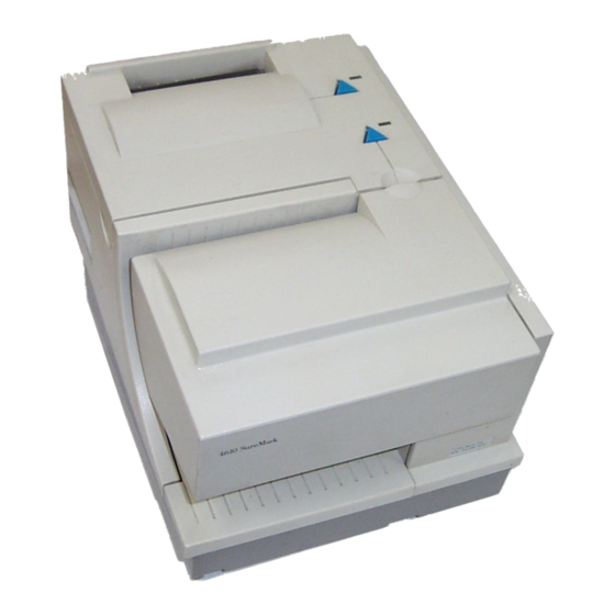
August 24, 2004 v Model TI8 provides a document scanner and a powered flipper, in addition to all the features of Model TI4. v Models TF6 and TM6 are single-station thermal printers. They contain no document insert station. These models cost less, weigh less, and have a smaller footprint than the thermal/impact SureMark printers. -
Page 33: Warranty Information
500 Series systems. For Retail customers, Model TM6 covers match the IBM 4694 systems if the RS-232/RS-485 interface is ordered, and the covers match the IBM SurePOS 700 Series systems if the USB interface is ordered. Table 1 shows the warranty information for each printer model. -
Page 34: Features Used With The Suremark Printers
Depot repair IOR 24x7, 9x5 TM6 but with Depot warranty Note: IOR 24x7 is IBM onsite repair 24 hours times seven days per week. 9x5 is nine hours per day for five days per week. Features used with the SureMark printers... -
Page 35: Comparison Of The Suremark Models
– ADXPJPFF.DAT for Models TI3, TI4, TG3, and TG4 – ADXPJP2F.DAT for Models TI3, TI4, TG3, and TG4 with the 2-MB card option – For microcode update information for the Model TI8, see the IBM Retail Store Solutions Web site at: http://www.ibm.com/solutions/retail/store. -
Page 36: Planning Information
August 24, 2004 The single-station SureMark printers have a lower weight, lower cost, and smaller footprint than the thermal/impact printers. The single-station SureMark printers are designed to provide a cost-effective printer in environments that do not require document printing and check processing. The single-station SureMark printers are spill-resistant, which makes them a good choice for food service customers. -
Page 37: Limitations
August 24, 2004 If you plan to use USB communications, you are responsible for ordering one of the following: v A powered USB cable. The 3.8-m USB cable for a distributed configuration is P/N 01L1647 and the 0.5-m USB cable for an integrated configuration is P/N 01L1646. -
Page 38: Suremark Printer Dimensions - Models Ti1, Ti2, Ti3, Ti4, Tg3, And Tg4
August 24, 2004 Models TI1, TI2, TI3, TI4, TG3, and TG4 Width 190.5 mm (7.5 in.) Depth 255 mm (10 in.) Height Front: 140 mm (5.5 in.), Rear: 190 mm (7.5 in.) Weight 4.4 kg (9.6 lb) Figure 2. SureMark Printer dimensions – Models TI1, TI2, TI3, TI4, TG3, and TG4 Model TI8 Width 190.5 mm (7.5 in.) -
Page 39: Suremark Printer Dimensions - Model Ti8
August 24, 2004 Figure 3. SureMark Printer dimensions – Model TI8 Models TF6 and TM6 Width 145 mm (5.7 in.) Depth 177 mm (7.0 in.) Height Front: 95 mm (3.7 in.), Rear: 121 mm (4.8 in.) Weight 1.4 kg (3.0 lb) without paper Chapter 1. -
Page 40: Power Requirements
When the SureMark is operating in RS-485 mode, power is supplied to the printer from the IBM POS system. The system supplies 38V dc and 5V dc to the printer. When the SureMark has the USB feature installed and is using the powered USB cable with a SurePOS 700 Series system, 24V is supplied from the system unit. -
Page 41: Software Requirements
4690 Operating System Version 1 at maintenance level 9910, 4690 OS V2 or 4690 OS V2R3 v IBM PC DOS 2000 or later with POSS for DOS V1.60(b) plus delta package 160(D), or later v Windows 2000 Professional with: –... -
Page 42: Resident Code Pages
Application Name Product Maintenance Level Number IBM SUREPOS Application Client/Server 5745-C44 Environment for 4690 OS IBM Chain Drug Sales Application 5669-212 9701 with PRPQ 5799-QYP IBM 4680/4690 General Sales Application 5696-546 9701 with APAR IR33229 and PRPQ 5799-QYN IBM 4680/4690 Supermarket Application... - Page 43 August 24, 2004 v Codabar v Code 128C v Codes 128A, 128B, and 128C (only Models TI3, TI4, TI8, TG3, TG4, TF6 and TM6) v Code 93 v PDF417 Chapter 1. Introduction...
- Page 44 August 24, 2004 SureMark Printers User’s Guide...
-
Page 45: Chapter 2. Installation Instructions
Any equipment to which this product will be attached must also be connected to properly wired receptacles. Note: For translations of these safety notices, see IBM Safety Information — Read This First, GA27-4004. Unpacking the printer Note: Save all packing material and shipping containers. -
Page 46: Installing The Suremark Printers
August 24, 2004 Installing the SureMark printers Installing for RS-232/RS-485 communication 1. Power the system off and disconnect the RS-232 power supply. 2. Locate the rear cable connectors. 3. If you are using the RS-232 communication port: a. For all models except TI8, check the settings on the RS-232 mode switch, which is near the rear cable connections. -
Page 47: Cable Connectors For Single-Station Suremark Printers
August 24, 2004 Power supply port (RS-232 only) RS-232 port RS-485 port Cash drawer connector Figure 6. Cable Connectors for Single-Station SureMark Printers. (View is from the bottom rear of the printer) RS-232 mode switches Cash drawer connector Figure 7. RS-232 Mode Switches for Single-Station SureMark Printers. (View is from the bottom rear of the printer) 5. - Page 48 August 24, 2004 Cash drawer cable Cash drawer cable Power cord RS-485 cable RS-232 cable Figure 8. RS-232 and RS-485 Cable Routing for Single-Station SureMark Printers 6. Connect any other signal cables for I/O devices to the correct ports. 7. Check that all signal cables are installed and seated in the correct ports. 8.
-
Page 49: Installing Suremark For Usb Communication
August 24, 2004 10. For single-station SureMark printers, turn on the power on/off switch on the printer. 11. For thermal/impact SureMark printers, locate the ribbon cartridge and install it in the printer. (See “Ribbon loading” on page 51.) Be sure that the ribbon is routed through the printhead correctly. - Page 50 August 24, 2004 Power supply port Powered USB port Standard USB port Cash drawer connector Figure 10. USB Ports for Single-Station SureMark Printers. (View is from the bottom rear of the printer) 3. For single-station printers, route any power cord and cables as shown in Figure 11.
- Page 51 August 24, 2004 6. Check that all signal cables are installed and seated in the correct ports. 7. If you are installing the printer on an integrated SurePOS 700 Series system: a. For single-station printers, place the printer in the square-shaped filler panel.
-
Page 52: Using The Wall Mounting Feature
August 24, 2004 Using the wall mounting feature Because of their light weight and small footprint, the single-station SureMark printers can be mounted on a wall. This is a useful feature when counter space is limited. To use the printer with the wall mounting feature: 1. -
Page 53: Installing The Fillers
August 24, 2004 Installing the fillers Installing fillers for RS-232/RS-485 printers Notes: 1. On an integrated unit, pull out on the locking lever at the left side of system unit. 2. Ensure that the side of each filler overlaps the tab on the side of the system unit. -
Page 54: Installing The Fillers For Rs-232/Rs-485 Systems
August 24, 2004 Knockout Alignment Section Ring Display Filler Printer Filler Display Filler Keyboard Filler Locking Lever Cable Figure 13. Installing the Fillers for RS-232/RS-485 Systems SureMark Printers User’s Guide... -
Page 55: Installing Fillers For Usb Printers
August 24, 2004 Installing fillers for USB printers 1. Disconnect the power brick from the printer, if one is connected. 2. Place the display filler appropriate for the video display on the system unit. Do not remove the knockout section unless you have an integrated video mount. See Figure 14 on page 28. -
Page 56: Installing The Fillers For Usb Systems
August 24, 2004 Alignment Knockout Ring Section Display Filler Printer Filler Display Filler Keyboard Filler Cable Locking Lever Figure 14. Installing the fillers for USB systems SureMark Printers User’s Guide... -
Page 57: Rs-232 Communication Mode Selections - All Models Except Ti8
August 24, 2004 Figure 15. SurePOS 500/600 integration RS-232 communication mode selections — all models except TI8 Switch settings described in this section apply only when the printer is connected to the system with the RS-232 cable. The switch is accessible without removing the printer covers. -
Page 58: Dtr/Dsr Control
August 24, 2004 Use switch 2 on the RS-232 settings switch to select the mode. Switch settings are: Switch 2 OFF DTR/DSR control Switch 2 ON XON/XOFF control (must use with a 3-wire interface) The printer normally ships with switch 2 in the OFF position, which selects DTR/DSR control. -
Page 59: Xon/Xoff Control
August 24, 2004 DTR operation: A DTR signal becomes inactive when the system is not ready to receive data (for example, at power-on reset or when its buffer is full). XON/XOFF control XON definition: = DC1 (X'11') XOFF definition: = DC3 (X'13') During XON/XOFF control, the printer transmits an XON every 3 seconds after a power on reset (POR) completes to indicate the printer is ready to receive data. -
Page 60: Rs-232 Communication Mode Selections - Model Ti8
August 24, 2004 RS-232 communication mode selections — Model TI8 Settings described in this section apply only when the printer is connected to the system with the RS-232 cable. Baud rate selection You must have power ON and paper installed in the thermal print station. 1. -
Page 61: Usb Communication Mode
SureMark to personal computers. The powered USB port is used to attach the SureMark to IBM POS systems. See Figure 9 on page 21 for the thermal/impact SureMark printers and Figure 10 on page 22 for the single-station SureMark printers. - Page 62 August 24, 2004 SureMark Printers User’s Guide...
-
Page 63: Chapter 3. Suremark Installation, Service, And Utility Software
Limitation on updating firmware ....41 Emulating the IBM Model 3 or Model 4 printers ... . . 41 Enabling emulation using utility diskettes . -
Page 64: Using The Reference/Service Diskettes (Rs-485 Or Rs-232 Printers)
August 24, 2004 Table 2. Adjustment procedures using the Point-of-Sale Device Diagnostics Procedure Character Alignment Adjustments DI Front Load Adjustment Adjustments Backlash Adjustment (Landscape) Adjustments Engineering Use Only Read MCT Firmware Update Firmware Update Reset Thermal Print Head Statistics Reset Stats Reset CR Motor Statistics Reset Stats Reset Impact Print Head Statistics... - Page 65 August 24, 2004 CURRENT ADJUSTMENT VALUES H 5 = Character alignment TL5 = Top line front insert Measure from the top edge of this BL3 = Bottom line top insert paper to the top of each print line. Press the key (1-9) that corresponds to the print line that is closest to 5MM.
-
Page 66: 4610 Fonts And Logos Utility Diskette
Message file v Logo file Proportional font conversion utility As part of its support for proportional fonts, IBM provides three TrueType fonts and a utility that you can use to convert the fonts to files that the SureMark printer can use. -
Page 67: Using A Firmware Update Diskette
August 24, 2004 Using a firmware update diskette Use a firmware update diskette to update the firmware in configurations when the SureMark is attached by either an RS-232 or RS-485 cable, and the system has a floppy diskette drive, a PC keyboard, and display. 1. -
Page 68: Ibm Point-Of-Sale Device Diagnostics
AIP46MCD.HEX for Models TI3, TI4, TG3, TG4, TF6, and TM6 with the 2-MB memory option. v For Model TI8, see the IBM Retail Store Solutions Web site at: http://www.ibm.com/solutions/retail/store. 2. Copy the latest SureMark firmware update image file to the C:\POS\BIN directory. -
Page 69: Limitation On Updating Firmware
Model 4 printers” for additional information. Emulating the IBM Model 3 or Model 4 printers It is possible to emulate the IBM Model 3 or Model 4 printer with the SureMark printer. You must change the configuration to enable the SureMark to emulate the Model 3 or Model 4 printers. -
Page 70: Limitations For Emulation
August 24, 2004 2. Press Ctrl-Alt-Delete to reboot the system. The system IPLs. To disable when emulation is currently enabled: 1. Select Disable Model 4 emulation. 2. Enter Ctrl-Alt-Delete to reboot the system. The system IPLs. Limitations for emulation The following limitations must be considered when using the SureMark printer to emulate the Model 3 or Model 4 printer. -
Page 71: Emulating An Epson Single-Station Printer (Single-Station Only)
August 24, 2004 2. To stop printing the data, open and close the ribbon cover. When you are ready to print the data, use the procedure above to restart printing from the beginning. 3. To stop printing and restart at the current position, open and close the paper cover. -
Page 72: Limitations For Epson Emulation
README files and information about OEM papers that have been certified. Select Support at the left on the main page of the Web site, then select IBM SureMark Printer. The displayed page contains links both to documentation and to diskettes and drivers that you can download for the SureMark printers. -
Page 73: Part 2. Models Ti1, Ti2, Ti3, Ti4, Ti8, Tg3, Tg4
August 24, 2004 Part 2. Models TI1, TI2, TI3, TI4, TI8, TG3, TG4 This part contains operational, testing, and problem determination information for the thermal/impact SureMark printers - models TI1, TI2, TI3, TI4, TI8, TG3, TG4. © Copyright IBM Corp. 1997, 2004... - Page 74 August 24, 2004 SureMark Printers User’s Guide...
-
Page 75: Chapter 4. Operation (Models Ti1, Ti2, Ti3, Ti4, Ti8, Tg3, And Tg4)
Printer Ready LED Document Printer Customer Receipt Feed Button Document Present LED Document Feed Button Figure 18. SureMark Printer - Indicators, Controls, and Printing Stations (Models TI1, TI2, TI3, TI4, TI8, TG3, and TG4) © Copyright IBM Corp. 1997, 2004... - Page 76 August 24, 2004 The printer is capable of printing verification information on a check and printing information on an inserted document. Figure 19 shows the correct positioning of the check in a Model TI2, TI4, TI8, or TG4 printer. It also shows how to side load a document to align it exactly where you want it to be printed.
-
Page 77: Printable Area Of An Inserted Document (Portrait)
August 24, 2004 Insertion of Document (Side Load) Model Ti8 Print Position Figure 20. Side insertion of Documents in a Model TI8 Printer Figure 21 and Figure 22 on page 50 show the printable area on an inserted document for both portrait and landscape. 2.0 mm 83.0 mm (3.3 in) 5 mm minimum... -
Page 78: Printable Area Of An Inserted Document (Landscape)
August 24, 2004 17mm for landscape printing 83.0 mm (3.3 in) 10 mm minimum 51 mm (2.0 in) minimum 101.6 mm maximum when using check flipper 65 mm minimum when using check flipper Figure 22. Printable Area of an Inserted Document (Landscape) SureMark Printers User’s Guide... -
Page 79: Ribbon Loading
August 24, 2004 Ribbon loading 1. Open the ribbon cover. As the cover is opened, the printhead moves to a position where you can easily load a ribbon. Figure 23. Opening the Ribbon Cover 2. If there is already a ribbon cartridge installed, remove it by lifting it straight up. Note: You might need to grasp the body of the cartridge rather than the top to remove it. - Page 80 August 24, 2004 3. Maintain ribbon tension by turning the ribbon cartridge knob as shown in Figure 24 on page 51. Lower the cartridge into position until the notches on its sides snap into place on the printer guides. Once the cartridge is in place, turn the knob until the ribbon slides into place between the printhead and the ribbon shield.
-
Page 81: Paper Loading
August 24, 2004 Paper loading 1. Open the paper cover. 2. If there is any unused paper or if there is an empty paper roll core in the paper roll bucket inside the printer, remove it before inserting a new paper roll. You can throw the core in the trash can. -
Page 82: Paper Loading Path (Models Ti1, Ti2, Ti3,Ti4, Ti8, Tg3, And Tg4)
August 24, 2004 Not Correct Correct Paper Roll Thermal Platen Paper Roll Core Figure 27. Paper Loading Path (Models TI1, TI2, TI3,TI4, TI8, TG3, and TG4) 4. See Figure 27. Place the leading edge of the paper over the metal guide. 5. -
Page 83: Clearing Jams In The Check Flipper Area
August 24, 2004 Clearing jams in the check flipper area This procedure is for the SureMark Model TI2 and TI4 printers (MICR Reader and Check Flipper features) only. If a check jams in the Check Flipper mechanism: 1. Lift up the left front corner of the lower document insert cover and pull the cover from the printer. -
Page 84: Removing The Check Flipper Cartridge (Except Model Ti8)
August 24, 2004 Figure 29. Removing the Check Flipper Cartridge (except Model TI8) 4. Reach inside the document insert station and carefully remove the jammed check. 5. Reinstall the check flipper cartridge and the lower DI cover. SureMark Printers User’s Guide... -
Page 85: Micr Read Head Cleaning
August 24, 2004 MICR read head cleaning The MICR read head should be cleaned after 10 000 checks are processed or every 3 months. Insert the MICR reader cleaning card through the document insert station several times. (See Appendix A, “Consumable supplies” to order cleaning cards.) If cleaning the MICR read head does not solve a problem you are having, it might be that you are experiencing electromagnetic noise interference. -
Page 86: Thermal Printhead Cleaning
August 24, 2004 Thermal printhead cleaning The thermal printhead can be cleaned whenever print quality deteriorates. 1. Open the paper cover. 2. Using a cotton swab soaked in isopropyl alcohol, gently wipe the printhead several times on its print line and on the surrounding area. See Figure 30. 3. -
Page 87: Document Scanner Calibration (Model Ti8)
August 24, 2004 6. The scanner should be recalibrated after it has been cleaned. See “Document scanner calibration (Model TI8).” Registration Plate Print Head Scanner Surface Ribbon Access Cover Figure 31. Scanner and print head location, Model TI8 Document scanner calibration (Model TI8) The printer must have power ON. - Page 88 August 24, 2004 SureMark Printers User’s Guide...
-
Page 89: Chapter 5. Testing And Problem Analysis (Models Ti1, Ti2, Ti3, Ti4, Ti8, Tg3, And Tg4)
Any equipment to which this product will be attached must also be connected to properly wired receptacles. Note: For translations of these safety notices, see IBM Safety Information — Read This First, GA27-4004. Testing the printer When you power ON the SureMark printer, it runs a power-on self-test (POST). If the POST finds no errors, the printer is ready for operation. -
Page 90: Offline Tests
August 24, 2004 Printer Ready LED Customer Receipt Feed Button Document Present LED Document Feed Button 2. Check the status of the Printer Ready indicator: Printer ready indicator ON: The power-on self-test completed successfully. Printer ready indicator OFF or blinking: The POST failed. - Page 91 August 24, 2004 If pressing the document feed button does not feed the document, go to “Problem determination” on page 66. 2. Press and hold both buttons to enter offline mode. When the printer ready indicator begins blinking, release both buttons. 3.
-
Page 92: Micr Reader And Check Flipper Test (Models Ti2, Ti4, Ti8, And Tg4 Only)
August 24, 2004 3. The serial interface will be specified as RS232, RS485, or USB, depending on which interface is used to attach the printer to the system unit. 4. The line speed information appears only when the RS-232 interface is used. The value can be either 9.6 K Baud or 19.2 K Baud, depending on the RS-232 switch settings. -
Page 93: Micr Reader Test Results, Models Ti2, Ti4, And Tg4 - Good Noise Level
August 24, 2004 Figure 33. MICR Reader Test Results, Models TI2, TI4, and TG4 – Good Noise Level Magnetic: T1234567890T 0860861190A 0671 Optical 1: T1234567890T 0860861190A 0671 Optical 2: T1234567890T 0860861190A 0671 Composite result: T1234567890T 0860861190A 0671 The average MICR signal is 99% of normal Figure 34. -
Page 94: Rs-232 Hex Dump
August 24, 2004 RS-232 hex dump To enable hex dump mode for the printer, press and hold the both buttons while the printer is powered on. To exit, power OFF or reset the printer. Resetting the printer - offline 1. Press and hold both buttons (Customer Receipt Feed button and Document Feed button) to enter offline mode. - Page 95 August 24, 2004 Table 3. Troubleshooting – Models TI1, TI2, TI3, TI4, TI8, TG3, and TG4 (continued) If the problem is... Here’s what to do... Document insert station is not v Check the paper path. printing v Check to see if the ribbon is installed correctly. v Change the ribbon, go to “Ribbon loading”...
- Page 96 August 24, 2004 SureMark Printers User’s Guide...
-
Page 97: Part 3. Models Tf6 And Tm6
August 24, 2004 Part 3. Models TF6 and TM6 This part contains operational, testing, and problem determination information for SureMark Printer models TF6 and TM6, which are the single-station printers that support DBCS. © Copyright IBM Corp. 1997, 2004... - Page 98 August 24, 2004 SureMark Printers User’s Guide...
-
Page 99: Chapter 6. Operation (Models Tf6 And Tm6)
Or, you can advance the paper after loading to get rid of the glued paper. 4. Pull the end of the paper up over the paper roll and toward the back of the printer. © Copyright IBM Corp. 1997, 2004... -
Page 100: Paper Loading Path (Models Tf6 And Tm6)
August 24, 2004 Note: Refer to the label on the inside of the bottom cover for a diagram of how to load paper. 5. Close the paper cover. 6. Press the customer receipt feed button to advance the paper and verify that the paper is feeding correctly. -
Page 101: Thermal Printhead Cleaning
August 24, 2004 Thermal printhead cleaning The thermal printhead can be cleaned whenever print quality deteriorates. 1. Open the paper cover. 2. Using a cotton swab soaked in isopropyl alcohol, gently wipe the printhead several times on its print line and on the surrounding area. See Figure 38. 3. - Page 102 August 24, 2004 SureMark Printers User’s Guide...
-
Page 103: Chapter 7. Testing And Problem Analysis (Models Tf6 And Tm6)
Any equipment to which this product will be attached must also be connected to properly wired receptacles. Note: For translations of these safety notices, see IBM Safety Information — Read This First, GA27-4004. Testing the printer When you power on the SureMark printer, it runs a power-on self-test (POST). If the POST finds no errors, the printer is ready for operation. -
Page 104: Offline Test
August 24, 2004 Top cover Printer ready Customer receipt feed button 2. Check the status of the Printer Ready indicator: Printer Ready indicator ON: The power-on self test completed successfully. Printer Ready indicator OFF or blinking: The POST failed. 3. If the POST fails or if you suspect problems with your system, see “Problem determination”... -
Page 105: Rs-232 Hex Dump
August 24, 2004 The Printers S/N is 12345678 Microcode EC level is 30 Serial Interface: RS232 Serial Interface Serial Interface : 19.2K Baud, XON / XOFF |"#$%&'()*+,-./0123456789:;<->?ABCDEFGHIKJK LMNOPQRSTUVWXYZ[\]^_ abcdefghijklmnopqrstuvw xyz{|}~.CüéâäàåcêëèïîìÄÅÉæÆôöòûùÿÖÜø£ØSsáíóú · ÁÑGg¿ · · · · ¡ · · ÁÂÀ ¢... -
Page 106: Resetting The Printer - Offline
August 24, 2004 Resetting the printer - offline To reset the printer: 1. Open the top cover. 2. Power off the printer using the power on/off switch that is located in the right front corner of the printer. 3. Power on the printer. Problem determination Any problems that arise with a SureMark printer are either software errors or hardware failures. -
Page 107: Appendix A. Consumable Supplies
IBM’s specifications. Some inks and printing processes will work acceptably, while others will not. Printer problems that are caused by supplies that do not meet IBM’s specifications may result in a billable service call, regardless of the existence of a service contract. -
Page 108: Document Insert Forms (Models Ti1, Ti2, Ti3, Ti4, Ti8, Tg3, And Tg4 Only)
August 24, 2004 Document insert forms (Models TI1, TI2, TI3, TI4, TI8, TG3, and TG4 only) The printers will accommodate single and multipart forms. Single and multipart form specifications | | | Specification Value Minimum width: 50 mm (2 in.) Maximum thickness of multipart forms: 0.47 mm (0.0185 in.) Maximum thickness of front sheet, multipart... -
Page 109: Micr Reader Read Head Cleaning Cards (Models Ti2, Ti4, Ti8, And Tg4 Only)
A package of 10 cards for cleaning the MICR reader’s read head is available from IBM as part number 73G2600. The MICR reader’s read head should be cleaned every 10 000 checks or every 3 months. Appendix A. Consumable supplies... - Page 110 August 24, 2004 SureMark Printers User’s Guide...
-
Page 111: Appendix B. Technical Information
Models TF6 and TM6, an impact printer mechanism. SureMark printers do not contain a power supply. However, they do contain voltage conversion circuitry to allow connection to a standard IBM system interface or to an RS-232 24-volt power supply. (See “Power requirements” on page 12 for specific power supply specifications.) - Page 112 August 24, 2004 Table 5. Station characteristics Characteristic Customer Receipt Station Document Insert Station Speed (see note TI1/TI2 – 19.6 lps at 6 lpi, 26 lps at 8 lpi; 4.3 lps following table) TI3/TI4/TI8/TG3/TG4 – 39.2 lps at 6 lpi, 52 lps at 8 lpi;...
-
Page 113: Memory Units
August 24, 2004 Memory units Random access memory (RAM) is used for storing the image data for the thermal printhead and program code. It is also used for storing incoming data from the communication port. Flash memory is used for many purposes, including: v Character set storage (80 KB) v Personalized message storage (8 KB) v Logo or APA message storage (64 KB) -
Page 114: Rs-485 Serial I/O Parameters
BWAIT-48H extra bits/byte (after printer data bytes) For more information about serial I/O communications, see 4680 Store Systems Serial I/O Channel Attachment Information, which is available from IBM Industry Corporate Relations. Cash drawer connector pin assignments The SureMark printers have a single cash drawer connector. This connector can drive either a single cash drawer (see “Description of models”... -
Page 115: Rs-232 Parameters
August 24, 2004 Signal Not Connected Transmit Receive DTR (Not connected on 3-wire cable) Signal Ground DSR (Not connected on 3-wire cable) Not Connected Not Connected See “Description of models” on page 4 for the cable part number. RS-232 parameters Protocol DTR/DSR mode or XON/XOFF mode. -
Page 116: Code Page Definitions
August 24, 2004 Signal Vbus (+5 V dc) Minus data Plus data Ground The powered USB connector has the following pin functions: Signal Ground (+24 V dc) +24 V dc Ground (Vbus) Plus data Minus data Vbus +5 V dc +24 V dc Ground (+24 V dc) See “Description of models”... -
Page 117: Generic Code Page
August 24, 2004 Generic code page Hex 1st ° ¥ § Figure 40. Printer’s Resident Character Set - Generic Code Page Appendix B. Technical information... -
Page 118: Code
August 24, 2004 Code page 437 Figure 41. Code Page 437 SureMark Printers User’s Guide... -
Page 119: Code
August 24, 2004 Code page 858 Hex 1st Ç É á ð Ó ü æ í Ð ± " é Æ ó Ê Ô â ô ú Ë Ò ä ö ñ È õ à ò Ñ Á Õ & å... -
Page 120: Code
August 24, 2004 Code page 860 Figure 43. Code Page 860 SureMark Printers User’s Guide... -
Page 121: Code
August 24, 2004 Code page 863 Figure 44. Code Page 863 Appendix B. Technical information... -
Page 122: Code
August 24, 2004 Code page 865 Figure 45. Code Page 865 Character fonts This section describes font capabilities. For more information about font-related commands, see: v “Download user-defined characters” on page 116 v “Set print station” on page 131 v “Set print mode” on page 127 v “Set code page”... -
Page 123: Impact Printing Fonts (Models Ti1, Ti2, Ti3, Ti4, Ti8, Tg3, And Tg4)
August 24, 2004 v Font C, starting with level 38 micro code is 8 dots (wide) and 20 dots (high) with the last 2-dot row used for descenders (1.0-mm × 2.5-mm character height including descenders, 1.0 mm × 2.25 mm excluding descenders). The number of characters printed per inch depends on the character size, the inter-character spacing, and the chosen font. - Page 124 August 24, 2004 2. User-defined characters greater than 9 dots high cannot be printed in landscape mode. 3. The portrait document print line is 80.35 mm (3.16 inches) long. There are 474 half-dots per line for font A, and 379 half-dots per line for font B. The landscape print line depends on the size of the document inserted.
-
Page 125: Appendix C. Rs-232 Programming Information
Select character for reprinted lines ....139 Reinitialize the printer ..... 139 © Copyright IBM Corp. 1997, 2004... - Page 126 August 24, 2004 Enable or disable the feed buttons (Models TI3, TI4, TI8, TG3, and TG4 only) ......140 Enable or disable the beeper (Models TF6 and TM6 only) .
- Page 127 August 24, 2004 Status byte 4 ......167 Status byte 5 ......167 Status byte 6 .
-
Page 128: Rs-232 Commands Summary By Function
95, and Windows 3.1x User’s Guide The 4690 OS manual is available on the current maintenance diskette for the IBM 4690 Operating System. Current versions of all three manuals are available on the Internet. See “Resources on the Internet” on page 44 for more information. - Page 129 August 24, 2004 Table 10. RS-232 commands organized by function (continued) Description Command Page Extended Microcode tolerance ESC M n h l or X'1B4D;n;h;l'. (MCT) information - loading (Model TI8) Microcode tolerance (MCT) ESC S n or X'1B53;n' information - request Extended Microcode tolerance ESC S n or X'1B53;n' (MCT) information - request...
- Page 130 August 24, 2004 Table 10. RS-232 commands organized by function (continued) Description Command Page Enable/disable the beeper ESC BEL n1 n2 or X'1B;07;n1;n2' Enable/disable upside-down ESC { n or X'1B 7B n' printing Select character size for scalable GS ! n or X'1D;21;n' fonts Fix font matrix ESC : n or X'1B 3A n'...
- Page 131 August 24, 2004 Table 10. RS-232 commands organized by function (continued) Description Command Page Retrieve size of user flash storage ESC 4 x ’03 FF FF FF’ or X'1B;34;03;FF;FF;FF' Retrieve printer usage statistics X'1B 51 xx' Check Processing Commands MICR read ESC I or X'1B49' Flip check ESC 5 or X'1B35'...
- Page 132 August 24, 2004 Table 10. RS-232 commands organized by function (continued) Description Command Page | | | Select printable area ESC X or X'1B;58;x;y;dx;dy' | | | Select printing direction/position ESC T n or X'1B;54;n' | | | Set vertical position GS $ y or X'1D;24;y' | | | Set relative vertical position...
-
Page 133: Alphabetized Rs-232 Commands Summary
August 24, 2004 Alphabetized RS-232 commands summary Table 11. RS-232 commands in alphabetical order Description Command Page Align positions ESC a n or X'1B61;n' Clear print data in page mode CAN or X'18' Disable line count ESC 8 n or X'1B;38'n Define document wait time ESC f x y or X'1B66;x;y' Download graphics (logo) - Page 134 August 24, 2004 Table 11. RS-232 commands in alphabetical order (continued) Description Command Page Print PDF417 bar code GS P data NUL or X'1D;50;data;00' Print predefined graphics (logo) GS / m logo# or X'1D2F;m;logo#' command Print predefined messages GS ^ message# or X'1D5E;message#' | | | Print scanned image X'1B;30;n1;x;y;dx;dy;s1;s2;n2'...
- Page 135 August 24, 2004 Table 11. RS-232 commands in alphabetical order (continued) Description Command Page Select compression format and X'1B;4d;x;n1;n2' scanned image threshold Select font for HRI GS f n or X'1D66;n' Select horizontal size of bar code GS w n or X'1D77;n' | | | Select page mode ESC L or X'1B;4C'...
- Page 136 August 24, 2004 Table 11. RS-232 commands in alphabetical order (continued) Description Command Page Set relative position ESC \ n1 n2 or X'1B5C;n1;n2' | | | Set relative vertical position GS \ y or X'1D;5C;y' Set sheet eject length ESC C n or X'1B43;n' | | | Set vertical position GS $ y or X'1D;24;y'...
-
Page 137: System Commands
August 24, 2004 System commands Exercise program RS-232 Syntax: ESC x or X'1B;78' Purpose: This tests printing functions of the printer. A test message is printed. (See Figure 32 on page 63.) If there is a document in the printer, the test message prints on the document. - Page 138 August 24, 2004 Status byte 5, bit 0 is set to 1 when responding to the extended address command. (See “Status summary” on page 165.) where: Byte 1 v Device type = X'30' for non-TI8 models and for Model TI8 in TI4 mode v Device type = X'31' TI8 models in TI8 mode Byte 2...
-
Page 139: Preset Or Onetime-Set Commands
August 24, 2004 Bit 0 Set to 1 when printer is set for 58 mm paper Bit 1 Set to 1 if Model TI8 is in TI4 mode Bits 2 – 7 Reserved Byte 5 EC level = EC level of loaded code Error Conditions: None. -
Page 140: Download Graphics (Logo) Commands
August 24, 2004 v User-defined impact characters v Logos v Predefined messages v User storage This allows greater flexibility in allocating memory because you can allocate additional memory for one function that has not been used by another function. There are twenty-two 64 KB sectors, for a total of 1.4 MB of flash memory available for allocation. - Page 141 August 24, 2004 range = 1 to 255 for a thermal logo. range = 1 to 5 for an impact logo. data The data to form the graphics image. The number of data bytes for the image is n1 × n2 × 8 Purpose: To store all-points-addressable print messages.
-
Page 142: Predefine Messages
August 24, 2004 Example: n1 = 2 & n2 = 2 For Thermal Graphics - Defined as: X'1D2A010202AAAAAAAAAAAAAAAAAAAAAAAAAAAAAAAA 55555555555555555555555555555555' For Impact Graphics - Defined as: X'1D2A020202FF00FF00FF00FF00FF00FF00FF00FF00 00FF00FF00FF00FF00FF00FF00FF00FF' Error Conditions: Flash EPROM load error - Verify the sector was erased before downloading images. - Page 143 August 24, 2004 v “Print predefined graphics (logo) command” on page 154 can be included in this command. v The size of all predefined messages cannot exceed 8000 bytes. Example: Store a trailer message: X'1D3A01' ’Thank You For Shopping’ X'0D' ’...
-
Page 144: Download User-Defined Characters
August 24, 2004 Download user-defined characters RS-232 Syntax: ESC & s n m data or X'1B26;s;n;m;data' where: The character set being defined. User-defined thermal code page 1 User-defined thermal code page 2 User-defined thermal code page 3 User-defined thermal code page 4 User-defined impact code page 1 User-defined impact code page 2 The beginning ASCII address of the characters being defined. -
Page 145: Proportional Font
August 24, 2004 The number of data bytes per character loaded is 2 × the character height. The total number of data bytes for this command is 2 × the character height × (1+m−n). Example: 10 wide × 20 high Defined as: X'1B26014848 C0C0C0C0C0C0C0C0C0C0C0C0C0C0FFC0FFC0F C0C0C0C0C0C0C0C0C0C0C0C0C0C0C0C0C0C0'... - Page 146 August 24, 2004 station. Each character in the code page has its own unique width and height. The matrix must be within the following ranges: Width 8 ≤ width ≤ 32 Height 8 ≤ width ≤ 32 Remarks: v Proportional and standard fonts may be used on the same line. If both types of fonts are used on a line, you would probably use proportional fonts for the description and resident fonts for the amounts.
-
Page 147: Impact Code Page
August 24, 2004 This command specifies a character width of 12 dots (X'0C') and a character height of 22 dots (X'16'). Following the width and height are 64 bytes that define the character. If, as in this case, the character is defined before all 64 bytes have been used, the rest of the bytes are filled with X'0' (see Figure 46). -
Page 148: Flash Storage Write
August 24, 2004 The number of data bytes per character loaded is 2 × character width. The total number of data bytes for this command is 2 × character width × (1+m−n). Each slice is defined with two bytes; the most significant bit (MSB) of each slice is the bottom of the character. -
Page 149: Erase Flash Eprom Sector
August 24, 2004 Erase flash EPROM sector RS-232 Syntax: ESC # n or X'1B;23;n' where: downloaded graphics predefined messages user-defined impact character set user-defined thermal character sets flash storage 06 - 07 Reserved check storage area 09 - FF Reserved Purpose: To erase the flash EPROM before downloading the data into the printer. -
Page 150: Microcode Tolerance (Mct) Information - Loading
August 24, 2004 Microcode tolerance (MCT) information - loading RS-232 Syntax: ESC M n h l or X'1B;4D;n;h;l' where: Microcode tolerance (MCT) that is being adjusted The high-order byte of MCT data The low-order byte of MCT data Purpose: The microcode tolerance (MCT) information is used to make adjustments to the printer’s microcode. -
Page 151: Microcode Tolerance (Mct) Information - Request
August 24, 2004 v If you try to set an MCT value out of its defined range, it is set to the closest limit (the minimum or maximum value) or rejected. Microcode tolerance (MCT) information - request RS-232 Syntax: ESC S n or X'1B;53;n' where: Microcode tolerance (MCT) information that is being requested Purpose:... - Page 152 0 = Line feeds are executed without regard for the state of DI ready. (IBM mode) Bit 14: v 1 = Normal operations (IBM mode) v 0 = Switch order of font A and font B (Epson mode) Bit 15: v 0 = Disable CR (X'0D') in CR station.
- Page 153 August 24, 2004 Table 13. MCT command definitions (continued) Default User-defined thermal character memory X'0001' X'0000' X'FFFF' allocation User-defined Logos X'0001' X'0000' X'FFFF' Predefined messages memory allocation X'0001' X'0000' X'FFFF' User flash storage memory allocation X'0002' X'0000' X'FFFF' Scan image storage memory allocation X'0010' X'0000' X'FFFF'...
-
Page 154: Extended Microcode Tolerance (Mct) Information - Request (Model Ti8 Only)
August 24, 2004 Table 13. MCT command definitions (continued) Default | | | | | | Scan storage template #2 predefined location DY0 | | | | | | Scan storage template #2 predefined location X1 | | | | | | Scan storage template #2 predefined location Y1 | | |... -
Page 155: Setup Commands
August 24, 2004 Setup commands Setup commands change character font, inter-character spacing, and the target print station. Set print mode RS-232 Syntax: ESC ! n or X'1B;21;n' where: Specifies print characteristics, such as user-defined thermal and impact code pages. Bit # ↓ Function Bit=0 Bit=1 Thermal... -
Page 156: Set Or Cancel Double-Wide Mode
August 24, 2004 Remarks: v For thermal printing with resident character sets: Font A = 10-dots (wide) × 20 dots (high) or 1.25 mm × 2.5 mm Font B = 12-dots (wide) × 24 dots (high) or 1.5 mm × 3.0 mm Font C = 8 dots (wide) ×... -
Page 157: Set Or Cancel Underline Mode
August 24, 2004 Remarks: See “Set or cancel unidirectional printing” on page 130. Set or cancel underline mode RS-232 Syntax: ESC − n or X'1B;2D;n' where: n=00 Cancel underline mode n=01 Set underline mode Default: n = 00 Remarks: This is valid in the customer receipt station only. Set or cancel overline mode RS-232 Syntax: ESC x‘5F’... -
Page 158: Set Or Cancel High-Quality Print Mode
August 24, 2004 Default: n = 00 Remarks: This must be at the beginning of a print-line in the document portrait station. It is enabled for the entire line. Set or cancel high-quality print mode This command is supported only for Models TI3, TI4, TI8, TG3, TG4, TF6, and TM6. -
Page 159: Set Print Station
August 24, 2004 Set print station RS-232 Syntax: ESC c 0 n or X'1B;6330;n' where: Specifies the print station. Bit # ↓ Station LSB 0 Reserved 1 Customer Receipt Station 2 Document Station - Portrait Mode 3 Document Station - Landscape Mode 4 Reserved 5 Reserved 6 Reserved... -
Page 160: Set Inter-Character Spacing
August 24, 2004 Default: n = 01 Remarks: Changing code pages is valid for resident character sets only. If user-defined character sets are enabled, this command will not do anything. Set inter-character spacing RS-232 Syntax: ESC SP n or X'1B20;n' where: The number of dot-spaces in the thermal print station or half-dot spaces in the impact print station. -
Page 161: Set Print Station Parameters
August 24, 2004 Set print station parameters RS-232 Syntax: ESC c 1 n or X'1B6331;n' where: Specifies the print station. Bit # ↓ Station LSB 0 Reserved 1 Customer Receipt Station 2 Document Station - Portrait Mode 3 Document Station - Landscape Mode 4 Reserved 5 Reserved 6 Reserved... -
Page 162: Select Color Printing
August 24, 2004 Note: Spacing in the document-portrait is actually 6.375 lines per inch. Line spacing dimension is approximate. For the impact printer in portrait mode, the actual line spacing must be calculated using 51 steps per inch. In the impact (document - landscape) station this would be set to 21 steps/line. -
Page 163: Set Sheet Eject Length
August 24, 2004 In the customer receipt station, 1 inch = 204 steps and 1mm = 8 steps. Thermal must be an even number. In the document portrait station, 1 inch = 51 steps and 1 mm = 2 steps. In the document landscape station, 1 inch = 127 steps and 1 mm = 5 steps. -
Page 164: Set Left Margin Position
August 24, 2004 Set left margin position RS-232 Syntax: ESC $ n1 n2 or X'1B24;n1;n2' where: The high-order byte of the dot offset from the beginning of the print line. The low-order byte of the dot offset from the beginning of the print line. -
Page 165: Align Positions
August 24, 2004 Align positions RS-232 Syntax: ESC a n or X'1B61;n' where: The type of alignment. Align Left Align Center Align Right Align Column Right Default: n = 00 Remarks: v Values 00, 01, and 02 are only valid at the beginning of a line. v Tabs are only valid when printing is aligned to the left. -
Page 166: Define Document Wait Time
August 24, 2004 Bit # ↓ Function Bit=0 Bit=1 LSB 0 Reserved 1 Reserved 2 Release Print Buffer after Error Release Hold Correction 32 Automatic retry on a Home Error Enabled Not Enabled 4 Hold buffer when waiting for a Release Hold document... -
Page 167: Status Sent To System
August 24, 2004 Status sent to system RS-232 Syntax: ESC ) n or X'1B29;n' where: Select function. Bit # ↓ Function Bit=0 Bit=1 LSB 0 Print Buffer Empty/Full 1 Reserved 2 Front Document Sensor Change 3 Top Document Sensor Change 4 After status byte 6 is incremented or status byte 3, bit 7, is set 5 Cash Draw Sensor Change... -
Page 168: Enable Or Disable The Feed Buttons
August 24, 2004 Setting Default Value Print Mode Print Station Selected User-Defined/Resident Character Sets Code Page Intercharacter Spacing (SB) Rotated Characters Station for line spacing Line Spacing all stations Six LPI Tab Positions every 100 dots Left Margin Relative Position Align Positions Unidirectional printing Horizontal Size of Bar Code... -
Page 169: Enable Or Disable The Beeper (Models Tf6 And Tm6 Only)
August 24, 2004 Enable or disable the beeper (Models TF6 and TM6 only) This command is supported only for Models TF6 and TM6. RS-232 Syntax: ESC BEL n1 n2 or X'1B 07 n1 n2' where: Enables or disables beeper. X'00' Disable beeper. -
Page 170: Enable Or Disable Upside-Down Printing
August 24, 2004 Enable or disable upside-down printing This command is supported only for Models TI3, TI4, TI8, TG3, TG4, TF6, and TM6. RS-232 Syntax: ESC { n or X'1B 7B n' where: Enables or disables upside-down printing. X'00' Disable upside-down printing. X'01' Enable upside-down printing. -
Page 171: Fix Font Matrix
August 24, 2004 Default: n = 00 Purpose: To select the size of a character. Remarks: v This command is valid only in the thermal print station. v Bits 3 and 8 of n are ignored. v The Set Print Mode command (see “Set print mode” on page 127) can also select the character height (double high and double wide). -
Page 172: Select Thermal Paper
August 24, 2004 LSB of the logo width. data The data to form the graphics image. Purpose: To print a small logo inline with characters. Remarks: v Thermal station only v Rotate characters must be disabled v n1 and n2 indicate the number of dots of the bit image in the horizontal direction. -
Page 173: Print Bar Code
August 24, 2004 Print bar code RS-232 Syntax: GS k n NUL or X'1D6B;n;data' where: Bar Code UPC-A UPC-E JAN13 (EAN-13) JAN8 (EAN-8) CODE 39 CODABAR CODE 128C CODE 93 CODE 128A, 128B, and 128C (this command is supported only for Models TI3, TI4, TI8, TG3, TG4, TF6, and TM6) data For n=00 through n=08, the ASCII representation of the characters to be printed. -
Page 174: Code
August 24, 2004 v For CODABAR, a stop and start character is required. v A leading zero will be added to the data for ITF bar codes if the data received has an odd number of bytes. v If a bar code width is greater than the paper width, the right of the bar code is truncated, making the bar code unreadable. -
Page 175: Code
August 24, 2004 Table 17. Code 128 character set (continued) Value Code Value Code Decimal Set A Set B Set C Decimal Set A Set B Set C FNC3 FNC3 FNC2 FNC2 SHIFT SHIFT CODE C CODE C CODE B FNC4 CODE B FNC4... -
Page 176: Select Horizontal Size Of Bar Code
August 24, 2004 Command = 1D 6B Data = 31 32 33 34 35 36 37 38 39 30 31 32 00 (hex) CODABAR Command = 1D 6B Data = 42 39 30 2E 2B 3A 2F 24 2D 43 00 (hex) CODE 128C Command = 1D 6B Data =... -
Page 177: Select Font For Hri
August 24, 2004 Default: n = 00 Remarks: Human readable information is normal text associated with the bar code. Note: The last valid value is kept when an invalid value is sent. Select font for HRI RS-232 Syntax: GS f n or X'1D66;n' where: The font for the HRI Font A... -
Page 178: Select Aspect Ratio Pdf417 Bar Code
August 24, 2004 Default: n1 = 00 n2 = 15 Range: 0 ≤ n1n2 ≤ 400 decimal (170 hex) Remarks: For 0 ≤ n1n2 ≤ 8, the ECC level is assumed as that particular security level. The security level determines the number of error correction codewords added to the symbol. -
Page 179: Enable Pdf417 Truncation
August 24, 2004 Enable PDF417 truncation RS-232 Syntax: GS T n or X'1D;54;n' where: Whether to enable truncation. 0 = Disable truncation. 1 = Enable truncation. Default: n = 0 Remarks: Truncated PDF generates a symbol with the right row indicator and stop pattern replaced by a single width bar. -
Page 180: Print And Feed Paper N Lines
August 24, 2004 Print and feed paper n lines RS-232 Syntax: ESC d n or X'1B64;n' where: Specifies the number of line feeds. Purpose: Prints data in the print buffer and feeds the paper by the amount specified in this command. Print and feed paper using minimum units RS-232 Syntax: ESC J n or X'1B4A;n'... - Page 181 August 24, 2004 One-eighth the number of dots in the horizontal direction, (width = 8 × w) range = 1 to 72 for a thermal logo. range = 1 to 59 for an impact logo. In the receipt station, 1 = 8 dots = 1 mm. In the document station, 6 = 48 dots = 1 inch.
-
Page 182: Print Predefined Graphics (Logo) Command
August 24, 2004 If this message is printed on a regular basis, consider downloading it to save communication time. (See “Download graphics (logo) Commands” on page 112.) The data buffer in the Model TI3 and Model TI4, which is 16 KB, can be used for signature capture. -
Page 183: Print Predefined Messages
August 24, 2004 Print predefined messages RS-232 Syntax: GS ^ message# or X'1D5E;message#' where: message# The number associated with the stored predefined message. v range = 1 to 25 for all models except TI8 v range = 1 to 25 for Model TI8 Purpose: To print predefined print messages. -
Page 184: Paper Cut/Di Eject
August 24, 2004 Register document v Close throat if open v Advance paper forward to first position 06-FF Reserved Purpose: To move the printhead to the desired location. Remarks: Valid at the beginning of the line only. Valid in impact print stations only. Paper cut/DI eject RS-232 Syntax: ESC i or ESC m or X'1B69 or 1B;6D'... -
Page 185: Retrieve Size Of User Flash Storage
August 24, 2004 In many RS-485 printers, the number of bytes retrieved should be kept under 200 to ensure that the system’s receive buffer is not overrun. The valid address range for each SureMark depends on the model number and which memory option, if any, is installed. Use “Retrieve size of user flash storage”... -
Page 186: Check Processing Commands (Models Ti2, Ti4, Ti8, And Tg4 Only)
August 24, 2004 Table 18. Retrievable usage data Hex Value Usage Data Being Tracked Factor FRU Card/Invalid usage numbers (set to X'0164' at the factory, not set for FRU logic cards) Number of paper cuts High byte of the number of characters printed on the CR None (thermal) station (see note 1) Low byte of the number of characters printed on the CR... -
Page 187: Micr Read
August 24, 2004 printer. For blank checks (no signature on the check) being processed through electronic check conversion, use the new MICR command X'1B3E01'. Both commands use the new OCR decoding algorithm for reading the MICR line, which is available on the Model TI8. MICR read RS-232 Syntax: ESC I or X'1B49'... -
Page 188: Flip Check
August 24, 2004 Character Description ASCII Representation hex value returned MICR data representation 0–9 Numerical data 0–9 30–9 blank Unreadable Character E13-B - Special characters Dash Transit On Us Amount CMC7 - Special characters Special character 1 Special character 2 Special character 3 Special character 4 Special character 5... -
Page 189: Asynchronous (Real-Time) Commands
August 24, 2004 Asynchronous (real-time) commands These commands are processed as soon as they are received. They do not go into the printer buffer. Note: These commands are not recognized when they occur in the middle of another command. For example, sending this command after the second byte of a 3-byte command, as in ESC J n. -
Page 190: Data Buffer Management And Batch Printing
August 24, 2004 Description Disable transparent XON/XOFF Purpose: To process a command immediately. Remarks: Either the Release print buffer or the Cancel print buffer command must be used in these situations: v When recovering from a cash receipt print error v After clearing an unrecoverable home error After the printer resets, it defaults to not sending status unless requested. -
Page 191: Document Handling
August 24, 2004 Remarks: The printer must be printing one line while processing the next line. If the printer is unable to completely process a line, the print speed reduces to half. The line count is reset when the buffer is held. Document handling To read checks, insert them from the front of the printer. -
Page 192: Landscape Mode
August 24, 2004 4a. FF: Print and Eject Document. Finish printing and eject the document. 4b. ESC q or ESC < X'01': Open Document Throat Finish printing and release the document from the printer’s rollers. Note: The document station stays selected - the printer will wait for another document until the station is changed. -
Page 193: Status Summary
August 24, 2004 The printer appears to be hung until an action is taken. If the document was previously loaded, the printer feeds the paper to the right margin on the document. 3. Send print lines to be printed in this station. The number of characters that can be printed on a line depends on the width of the document. -
Page 194: Status Byte 1
August 24, 2004 3 - 10 Status bytes 1-8. See the descriptions of each byte in the sections that follow. 11 - n Either 5 bytes of additional status from the “Extended address command–request printer ID” on page 109 command, or up to 246 bytes of user data that can include: v MICR data v User flash data... -
Page 195: Status Byte 3
August 24, 2004 Status byte 3 Description 0 (LSB) Memory sector is full. Home error. Document error. The document was not inserted after the document station was selected, and the wait subsequently timed out. Flash EPROM load error or MCT load error. Reserved. -
Page 196: Status Byte 7
August 24, 2004 Status byte 7 Description 0 (LSB) Reserved. Reserved Reserved Cash drawer status (0 if cash drawer status (port pin 3) at ground. Print key pressed (1 = pressed). Reserved. Defaults to 1. Station selected. Set to 1 when document insert station is selected. 7 (MSB) Document feed error. -
Page 197: Document Scanner Commands
August 24, 2004 Document scanner commands Scanner commands are supported on Model TI8 only. Start scan RS-485 syntax: X'1B;3E;n' RS-232 syntax: X'1B;3E;n' where: n = 00 optical scan only n = 01 scan and MICR/OCR read Remarks: v Pulls in document present at scanner input. v Document image is retained in RAM until another scan command is received, or the printer is reset. -
Page 198: Print Scanned Image
August 24, 2004 Print scanned image RS-485 syntax: X'1B;30;n1;x;y;dx;dy;s1;s2;n2' RS-232 syntax: X'1B;30;n1;x;y;dx;dy;s1;s2;n2' where: 2 bytes, reserved, X'00 00' 2 bytes each, top-left corner of area to be printed dx, dy 2 bytes each, offset in the x and y direction respectively, to be included in the print area 1 byte, percentage to scale image in the x direction (A value of 100 or 0 results in no scaling.) -
Page 199: Store Scanned Image
August 24, 2004 Store scanned image RS-485 syntax: X'1B;41;n1;x0;y0;dx0;dy0;x1;y1;dx1;dy1;x2;y2;dx2;dy2;x3;y3;dx3; dy3;tagdata' RS-232 syntax: X'1B;41;n1;x0;y0;dx0;dy0;x1;y1;dx1;dy1;x2;y2;dx2;dy2;x3;y3;dx3; dy3;tagdata' where: n1 Select storage method, one byte v X'00' store entire image v X'01' store image using template 1 v X'02' store image using template 2 v X'03' store image using user defined values x0, y0 2 bytes each, top-left corner of area to be stored dx0, dy0... - Page 200 August 24, 2004 (0,0) (x0,y0) (dx0) (dx1) (x1,y1) (dx2) Scanned Document (x2,y2) (dy1) (dy2) (dx3) (x3,y3) (dy3) (dy0) Figure 48. Scanned image organization Remarks: Images are stored sequentially. The locations where the images are stored are obtained with a Retrieve next table location command before issuing the store command.
- Page 201 August 24, 2004 should not be included. These parameters are defined in MCT locations X'0xB0' through X'0xBF' and can be viewed or adjusted using the MCT Read and MCT Write commands. If fewer than four blocks are required, a block can be disabled by storing a value of X'FFFF' to a coordinate MCT location.
-
Page 202: Data Table
August 24, 2004 Table 19. Data table Document width = 3 in. Document height = 6 in. x0 = 1.75 in. y0 = 4.25 in. dx0 = 0.40 in. dy0 = 1.0 in. x1 = 1.80 in. y1 = 1.0 in. dx1 = 1.0 in. -
Page 203: Retrieve Scanned Image
August 24, 2004 Retrieve scanned image RS-485 syntax: X'1B;39;n1;n2;n3' RS-232 syntax: X'1B;39;n1;n2;n3' where: v n1, 2 bytes, Image location to retrieve v n2, 4 bytes, Offset into image from which to retrieve data v n3, 2 bytes, Number of bytes to retrieve Remarks: Image location (n1) of 0 returns the image last scanned. -
Page 204: Scanner Calibration
August 24, 2004 For immediate images (n1=0), the image data format is the currently selected format. If any parameter is out of range, Command Reject is returned. Scanner calibration RS-485 syntax: X'1D 63 30' RS-232 syntax: GS c 0 or X'1D 63 30' Purpose: Used to initiate the calibration routine for the scanner in Model TI8 printer. -
Page 205: Select Compression Format And Scanned Image Threshold
August 24, 2004 Select compression format and scanned image threshold RS-485 syntax: X'1B;4d;x;n1;n2' RS-232 syntax: X'1B;4d;x;n1;n2' where: v x = X'1F' – address to store data v n1 – 00 TIFF-CCIT-Group 4 compression – 01 JPEG compression – 02 BMP (uncompressed) –... -
Page 206: Page Mode Printing Commands
August 24, 2004 Page mode printing commands Select page mode RS-485 Syntax: X'1B;4C' RS-232 Syntax: ESC L or X'1B;4C' Remarks: v Enables page mode printing. v Supported on thermal station only. v Starting position is set by Set printable area X'1B;57..' and Set print direction X'1B;54..' commands. -
Page 207: Select Printable Area
August 24, 2004 Select printable area RS-485 Syntax: X'1B;58;x;y;dx;dy' RS-232 Syntax: ESC X or X'1B;58;x;y;dx;dy' where: v x, y – Two-byte horizontal and vertical starting position (in dots) v dx, dy – Two-byte horizontal and vertical printing area (in dots) Remarks: v When sent in standard mode, this command sets the printable area for page mode, but has no effect on standard mode printing. -
Page 208: Set Vertical Position
August 24, 2004 Set vertical position RS-485 Syntax: X'1D;24;y' RS-232 Syntax: GS $ y or X'1D;24;y' where: y is a two-byte vertical printing position (in dots) Remarks: v Applies to page mode only. v Moves the printing position to the specified dot position perpendicular to the printing direction specified by the Select printing direction command. -
Page 209: Set Left Margin Position (Standard Mode), Set Absolute Print Position
August 24, 2004 Set left margin position (standard mode), set absolute print position (page mode) RS-485 Syntax: X'1B;24;n1;n2' RS-232 Syntax: ESC $ n1 n2 or X'1B;24;n1;n2' where: v n1 is the high-order byte of the dot offset from the beginning of the print line. -
Page 210: Set Relative Horizontal Position
August 24, 2004 Set relative horizontal position RS-485 Syntax: X'1B;5C;n1;n2' RS-232 Syntax: ESC <5C>h n1 n2 or X'1B;5C;n1;n2' where: v n1 is the high-order byte of the dot offset, relative to the left margin in standard mode or the current print position in page mode. v n2 is the low-order byte of the dot offset, relative to the left margin in standard mode or the current print position in page mode. -
Page 211: Print And Form Feed And Cut The Paper
August 24, 2004 Print and form feed and cut the paper RS-485 Syntax: X'0C' RS-232 Syntax: FF or X'0C' Epson compatibility syntax: FF or X'0C' Remarks: v In standard mode, the data in the print buffer feeds the paper in the CR station or DI station by a preset amount, until the document exits the feed rollers. - Page 212 August 24, 2004 SureMark Printers User’s Guide...
-
Page 213: Appendix D. Uploading Electronic Journal Data
27 undefined bytes Example: X'010100010C5E454A204449....' Upload the EJ data Command Syntax: X'0117' Remarks: In response to this command, the printer will send four status bytes, then 43 bytes of print data, followed by the line number. © Copyright IBM Corp. 1997, 2004... -
Page 214: Request The Size Of The Ej Space
August 24, 2004 The line number will be sent as decimal ASCII numbers. Request the size of the EJ space Command Syntax: X'0101xxxxxx'^EJSIze n1 where: 30 undefined bytes Example: X'010100010C5E454A204449....' Remarks: When the next MICR read command is sent after this command is sent, the SureMark will send the number of lines that are stored in the printer’s memory. -
Page 215: Appendix E. Proportional Fonts
Preparing the fonts Downloading proportional fonts to the SureMark is a 2-step process: 1. Convert a TrueType font to the SureMark proportional font format. Use the IBM Proportional Fonts Conversion Utility, fontconvert.exe, to convert the fonts. See “Proportional font conversion utility” on page 38. -
Page 216: Layout Using Set Tab Position
August 24, 2004 v Unlike other Align Position commands, the Align Positions-Align Column Right command can be sent in the middle of a print line. Print characters sent before the alignment command will be left aligned, while characters sent after the alignment command will be right aligned. - Page 217 August 24, 2004 3. Issue the Fix Font Matrix command with n=dot width of the widest number used. The command syntax is X'1B 3A xx'. Note: Finding the optimum value of xx for this command will vary depending on the proportional character set being used, and may require some experimentation.
- Page 218 August 24, 2004 SureMark Printers User’s Guide...
-
Page 219: Appendix F. Emulation Support For Epson Single-Station Printer
Epson single-station printer and the SureMark. Note: Ensure that the dip switch on the printer is set to "Other“, rather than "IBM“. Commands supported in emulation mode The commands listed in Table 21 are supported in Epson emulation mode. - Page 220 August 24, 2004 Table 21. Commands supported in Epson emulation mode (continued) Hex Command ASCII Command Description 1B 32 ESC 2 Select default line spacing 1B 33 n ESC 3 n Set line spacing 1B 3D n ESC = n Set peripheral device 1B 3F n ESC ? n...
-
Page 221: Commands With Limited Support In Emulation Mode
August 24, 2004 Commands with limited support in emulation mode The commands listed in Table 22 are supported in a limited manner in Epson emulation mode. The table describes the limitation on each command. Table 22. Commands with limited support in Epson emulation mode Command Description of Limitation 10 04 n... -
Page 222: Commands Not Supported In Emulation Mode
August 24, 2004 Commands not supported in emulation mode In Epson emulation mode, the SureMark printer supports all Epson commands except the page mode commands and smoothing. Table 23 lists the commands that are not supported. Table 23. Commands not supported in Epson emulation mode Hex Command ASCII Command Description of Limitation... -
Page 223: Appendix G. Notices
References in this publication to IBM products, programs, or services do not imply that IBM intends to make these available in all countries in which IBM operates. Any reference to an IBM product, program, or service is not intended to state or imply that only IBM’s product, program, or service may be used. -
Page 224: European Union (Eu) Mark Of Conformity Statement
In solch einem Fall ist der Abstand bzw. die Abschirmung zu der industriellen Störquelle zu vergrößern.″ Anmerkung: Um die Einhaltung des EMVG sicherzustellen sind die Geräte, wie in den IBM Handbüchern angegeben, zu installieren und zu betreiben. SureMark Printers User’s Guide... -
Page 225: Japanese Voluntary Control Council For Interference (Vcci) Statement
August 24, 2004 Japanese Voluntary Control Council for Interference (VCCI) Statement This product is a Class A Information Technology Equipment and conforms to the standards set by the Voluntary Control Council for Interference by Technology Equipment (VCCI). In a domestic environment this product may cause radio interference in which case the user may be required to take adequate measures. -
Page 226: Australia / New Zealand Compliance Statement
Warning: This is a Class A product. In a domestic environment this product may cause radio interference, in which case the user may be required to take adequate measures. Trademarks The following are trademarks of the IBM Corporation in the United States or other countries or both: the IBM logo SureMark... -
Page 227: Index
863 93 control description 30, 32 code page 865 94 selection 29 definitions 88 generic 89 resident 14 code pages, resident 14 EC request command 161 commands, immediate 85 edition notice ii © Copyright IBM Corp. 1997, 2004... - Page 228 9 emulate model 3 or 4 printer limitations 42 overview 41 upload electronic journal data 185 IBM Retail Store Solutions Web site 44 using utility diskettes 41 immediate commands 85 emulation, Epson 191 impact code page command 119...
- Page 229 August 24, 2004 MICR read print logo inline 143 head cleaning 57 print mode command, set 127 head cleaning cards 81 print predefined graphics (logo) command 154 read command 159 print scanned image command 170 MICR reader and check flipper test 64 print station command, set 131 microcode tolerance (MCT) print station parameters command, set 133...
- Page 230 August 24, 2004 reset line count 162 RS-232 commands (continued) reset printer 161 MICR read 159 resetting the printer microcode tolerance, loading 122 Models TF6 and TM6 78 microcode tolerance, request 123, 126 Models TI1, TI2, TI3, TI4, TI8, TG3, TG4 66 miscellaneous 155 resident code pages 14 onetime-set 111...
- Page 231 24 fonts 94 warranty information, all models 5 forms, single and multipart 80 Web site, IBM Retail Store Solutions 44 memory 85 weight, all models 9 MICR read head cleaning cards 81 where to order supplies 79...
- Page 232 August 24, 2004 SureMark Printers User’s Guide...
- Page 233 Thank you for your responses. May we contact you? h Yes h No When you send comments to IBM, you grant IBM a nonexclusive right to use or distribute your comments in any way it believes appropriate without incurring any obligation to you. Name...
- Page 234 IF MAILED IN THE UNITED STATES BUSINESS REPLY MAIL FIRST-CLASS MAIL PERMIT NO. 40 ARMONK, NEW YORK POSTAGE WILL BE PAID BY ADDRESSEE IBM Corporation Design and Information Development Dept CJMA/Bldg. 645 P. O. Box 12195 Research Triangle Park, NC 27709-9990...
- Page 236 Part Number: 54P1733 August 24, 2004 Printed in USA GA27-4151-05...
Need help?
Do you have a question about the 4610-TM6 - SureMark Printer TM6 Two-color Thermal Transfer and is the answer not in the manual?
Questions and answers