IBM 3 User Manual
4247 printer
Hide thumbs
Also See for 3:
- Installation and reference manual (72 pages) ,
- Quick installation manual (2 pages)
Table of Contents
Advertisement
Quick Links
Advertisement
Chapters
Table of Contents

Related Manuals for IBM 3


Summary of Contents for IBM 3
- Page 1 4247 Printer Model 003 User’s Guide S544-5780-01...
- Page 3 4247 Printer Model 003 User’s Guide S544-5780-01...
- Page 4 IBM representative or to the IBM branch office serving your locality. If you request publications from the address given below, your order will be delayed because publications are not stocked there. Many of the IBM Printing Systems Company publications are available from the web page listed below.
-
Page 5: Table Of Contents
Function Keys . 40 Chapter 6. Rear Tractor Use ..75 Menu . . 41 Quiet . 42 Chapter 7. Twinaxial Configuration. . . 77 Micro /Scroll or Micro /Scroll . 42 © Copyright IBM Corp. 2002... - Page 6 Full Page On Skip Suppress . 114 Continuous Forms Eject Mode. . 152 PS Print Direction . . 115 Manual Paper Overlay . . 152 Automatic Manual Load. . 153 Manual Feed Eject Mode . 154 4247 Model 003 User’s Guide...
- Page 7 Bar Code Print Direction . 154 Configuring Printer For Front Push Forms Path Graphics Print Direction . . 155 Loading Forms for Front Push. . 196 Perforation Safety . . 155 Rear Push Forms Path . . 199 Jam Sensors . .
- Page 8 Twinax Cable Specifications for Teflon Cable . . 347 Airflow . . 326 Installing Cable Connectors on Twinax Cable . . 348 Declaration of IBM Product Noise Emission Cable-to-Cable Adapters for Twinax Cable. . 351 Values . . 326 Ordering Signal Cables .
-
Page 9: Preface
Preface This guide describes the basic operating procedures for the IBM 4247 Printer Model 003. This information is useful to those who install or operate the printer, or for those who supervise printer operations. You need only basic operating experience to use this printer. This experience includes an understanding of how printers work, how to connect cables, and how to select items from an operator panel menu. -
Page 10: Related Publications
IBM 4247 Model 001 Programming Reference, SA24-4410. This manual describes the programming functions that control the printer, and includes information that is valid for the 4247 Model 003. This reference is not shipped with the printer. v IBM 4247 Printer Automatic Sheet Feeder Guide, SA24-4407. This manual describes the Automatic Sheet Feeder feature. -
Page 11: Chapter 1. Getting Started
Note: Any part on a 4247 printer that is blue or has a blue decal on it will be used in your daily operations of the printer. © Copyright IBM Corp. 2002... -
Page 12: Locations
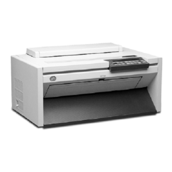
Manual Sheet Feed Tray Release Wire Forms Guide Push Tractor Paper Slot Tear Bar Power Cord Connector Automatic Sheet Feeder (ASF) Cover Rear Tractor Door Information Label Attachment Card Connector Acoustic Mat Parallel Interface Connector 4247 Model 003 User’s Guide... - Page 13 Chapter 1. Getting Started...
-
Page 14: Unpacking The Printer
Attachment card (if ordered - do not remove from protective package) h Operator panel overlays h Printer driver diskette h Power cord h Interface cable (if ordered) h Wire forms guide h Twinaxial V-connector (if twinax attachment was ordered) 4247 Model 003 User’s Guide... - Page 15 The table you select is sturdy enough to support the weight of the printer, and firm enough to contain the action of the printer movement. To meet this criteria, IBM recommends the optional printer stand which is available from your IBM marketing representative.
-
Page 16: Handling Attachment Card
If you have removed the attachment card from the protective package and cannot immediately insert it in the printer, place the protective package on a flat surface, and set the attachment card on top of the protective package. 4247 Model 003 User’s Guide... -
Page 17: Installing Optional Attachment Card
Installing Optional Attachment Card Use this procedure if you received an optional attachment card with your printer. Do not remove the attachment card from the protective package until you: v Read the information in “Handling Attachment Card” on page 6 v Are instructed to remove the card from the protective package The 4247 printer arrived with a parallel interface port permanently installed at the rear of the printer. - Page 18 Figure 5 on page 9 and Table 1. Table 1. Attachment Card Identification Item Number in Drawing Connector Type Parallel (permanently installed) Serial (25-pin D-shell connector) Twinax (15-pin D-shell connector) Coax (BNC connector) Ethernet LAN (RJ45 connector) 4247 Model 003 User’s Guide...
-
Page 19: Additional Installation Information For Lan Attachment Card
Figure 5. Connector Types - Rear of Printer Additional Installation Information For LAN Attachment Card The LAN attachment card utilizes the AXIS 5400 Network Print Server. The attachment card connects directly to the printer parallel port. If you are installing a LAN attachment card, you need to consider the following additional information. -
Page 20: Installing Wire Forms Guide
Installing Wire Forms Guide Open the acoustic cover and insert one end of the wire forms guide into a hinge block. Compress the wire forms guide and insert the other end into the other hinge block. 4247 Model 003 User’s Guide... -
Page 21: Installing Ribbon Cartridge
This forms guide will be used for forms stacking in the front push and rear push forms paths. Installing Ribbon Cartridge Attention: IBM recommends that you use an IBM ribbon cartridge. To order ribbon cartridges, contact your place of printer purchase or call Lexmark at 1-800-438-2468. - Page 22 Position the snap arm with the small lever up onto the ribbon lift assembly. Push the snap arm down onto the ribbon lift assembly until it snaps into place. 4247 Model 003 User’s Guide...
- Page 23 Ribbon Guide Ribbon Shield Printhead Ribbon Lift Assembly Cartridge Supports Figure 9. Installing Ribbon Cartridge 9. Align the ribbon mounting pins on the left and right side of the ribbon cartridge with the slots in the cartridge supports. Snap the ribbon cartridge down into place.
-
Page 24: Installing Forms Tractor
This illustration shows the front push forms path from the left side of the printer. Installing Forms Tractor in Front Push Position Note: Ensure that the printer is powered off (O) to perform this procedure. 4247 Model 003 User’s Guide... - Page 25 1. The front tractor cover should be in the open position. 2. Open the hinged gear protector cover by rotating it down out of the way. Chapter 1. Getting Started...
- Page 26 Both forms tractor release levers are in the locked (up) position c. The electrical connector tab is fully seated in the connector d. The bottom of the forms tractor is level with (same amount of space from) the base of the printer 4247 Model 003 User’s Guide...
-
Page 27: Connecting Power Cord
Connecting Power Cord Chapter 1. Getting Started... -
Page 28: Powering On Printer
Power Switch Figure 12. Powering On Printer 2. Wait until the message IBM 4247 appears, all segments (or character elements) of the LCD on the operator panel display are lighted, and DIAGNOSTICS IN PROGRESS appears, then is replaced by one of the following Ready messages. -
Page 29: Changing Display Language (From English)
READY <A> Coax Front READY <A> Parallel Front READY <A> Serial Front READY <A> Front For twinax or coax attachment: The printer has not been attached to a computer yet. Within the first minute after power-on, 015 COMMUNICATIONS CHECK will appear in the display. Press Stop to silence the alarm. -
Page 30: Loading Forms In Front Push Tractors
5. Put the left tractor holes of the form over the left tractor pins. Close the left tractor door. 6. Move the right tractor until the right tractor holes of the form fit on the right tractor pins. Ensure that the forms go under the forms jam sensor 4247 Model 003 User’s Guide... - Page 31 and that the forms are straight. 7. Close the right tractor door. 8. If necessary, slide the right tractor to the right side of the printer to remove the slack in the form. If the forms are too tight, slide the right tractor away from the right side of the printer.
-
Page 32: Printing Your First Document
Each parameter is shown with the corresponding values you can select printed to the right. 1. Ensure that the printer is offline. If the printer is ready, press Stop to make the printer not ready. 2. Press Test. 4247 Model 003 User’s Guide... -
Page 33: Attaching The 4247 Printer To Your Computer
YOU HAVE JUST COMPLETED A SETUP AND CHECKOUT OF THE PRINTER. IBM recommends that you now print your printer configuration defaults. Save this printout for future reference. You can create a printout of the printer configuration by following these steps: 1. - Page 34 To set the printer address, follow these steps: a. Power on (|) the printer. b. Wait until the message IBM 4247 appears, all segments of the LCD on the operator panel display are lighted, and the printer has stopped all motion.
- Page 35 i. Press Enter to set the address. An asterisk (*) appears beside the address. j. The 4247 printer supports several emulation modes. The default mode is native 4247. However, if your computer system is not at a software level that recognizes printer type 4247, change the printer emulation to 4230, 4224, or 4214, depending upon your requirements.
- Page 36 6. Connect the power cord to the printer and the wall outlet. 7. Power on (|) the printer. 8. Wait until the message IBM 4247 appears, all segments of the LCD on the operator panel display are lighted, and the printer has stopped all motion. The...
-
Page 37: Coax Attachment
4. Connect the power cord to the printer and to the electrical outlet. 5. Power on (|) the printer. 6. Wait until the message IBM 4247 appears, all segments of the LCD on the operator panel display are lighted, and the printer has stopped all motion. The... -
Page 38: Parallel Attachment
6. Power on (|) the printer. 7. Wait until the message IBM 4247 appears, all segments of the LCD on the operator panel display are lighted, and the printer has stopped all motion. -
Page 39: Serial Attachment
11. Press Scroll or Scroll until the printer displays: Attachment Parallel 12. Press Enter. An asterisk (*) will be displayed in front of the selected value. 13. Press Start. The printer displays: Press ENTER to Save a Custom Set Press START to Not Save in a Set 14. -
Page 40: Lan Attachment
4. Connect the power cord to the printer and to the electrical outlet. 5. Power on (|) the printer. 6. Wait until the message IBM 4247 appears, all segments of the LCD on the operator panel display are lighted, and the printer has stopped all motion. The... - Page 41 3. Connect the power cord to the printer and to the electrical outlet. 4. Power on (|) the printer. 5. Wait until the message IBM 4247 appears, all segments of the LCD on the operator panel display are lighted, and the printer has stopped all motion. The printer then displays: Chapter 1.
-
Page 42: About Ascii Printer Drivers
For OS/2 and Windows Operating Environment Windows drivers for the 4247 are not shipped with your printer, and must be downloaded from the web. They are found on the IBM Printing Systems web page at http://www.printers.ibm.com. 4247 Model 003 User’s Guide... -
Page 43: Installing Ascii Printer Drivers
You may, however, use the operator panel to select these features. v IBM 2381 Personal Printer v IBM 4202 Proprinter III XL v Epson FX 1050 Installing ASCII Printer Drivers The 4247 printer is supported by the following operating systems or environments: v AIX version 3.2.5 and later... -
Page 44: Os/2 Or Windows Printer Driver Installation
In addition to the drivers available on the diskette that is shipped with the 4247 printer, there are Windows drivers for the 4247 printer. These drivers must be downloaded from the web. They are found on the IBM Printing Systems Company web page at http://www.printers.ibm.com. -
Page 45: Completing Printer Setup
You may, however, use the operator panel to select these features. v IBM 2381 Personal Printer v IBM 4202 Proprinter III XL v Epson FX 1050 Completing Printer Setup Your 4247 Printer is now ready to use with the forms tractor mounted in the Front Push position and with the configuration parameters set to manufacturing defaults. - Page 46 4247 Model 003 User’s Guide...
-
Page 47: Chapter 2. Understanding The Operator Panel
Menu Scroll Enter Print Feed Feed Print Attention Micro Park/ Load/ Set Top Stop Quit Test Scroll Return Path Eject of Form Unit Check Figure 13. 4247 Printer Operator Panel (All Printers Without Twinax Attachment) © Copyright IBM Corp. 2002... -
Page 48: Status Indicators
Operator Print Tests The Ready indicator is not lighted because of one of the following conditions: v After pressing Stop v After detection of an intervention required condition v After detection of a printer error 4247 Model 003 User’s Guide... -
Page 49: Processing
Tests. You can set this display so the messages appear in one of the following languages: v 000 English (default) v 001 Deutsch v 002 Français v 003 Italiano v 004 Español v 005 Nederlands v 006 Dansk v 007 Português... -
Page 50: Audible Alarm
There are 16 keys available on the operator panel for performing printer functions. These keys perform general printer functions (for example, adjusting forms) and are used to scroll through and select items in the Configuration Menu and Operator Print Tests menu. 4247 Model 003 User’s Guide... -
Page 51: Menu
The keys on the right side of the panel have only one function, as designated by the label on the key. Menu and Quiet also have only one function each. The following keys on the left side have two functions each: v Micro /Scroll v Micro /Scroll v PA1/Enter (Coax only) -
Page 52: Quiet
MENU LOCKED For more information on the Menu Lock function, see your system programmer or the IBM 4247 Printer Model 001 Programming Reference. For more information on configuration parameters and values, see “Checking and Changing Parameter Values” on page 54. -
Page 53: Enter (Twinax)
Scrolling Through Categories, Parameters, Values, and Tests The scrolling functions are available only when the Configuration Menu or Test Menu is displayed. Pressing Scroll when the Configuration Menu is displayed changes the second line of the display to show the previous configuration category, parameter, or value. -
Page 54: Pa1/Enter (Parallel, Serial, Coax, Or Lan)
The Enter function is available when the Configuration Menu or Operator Print Tests Menu is displayed. Pressing Enter selects the displayed option. The Enter function is also used during some of the tests. PA2/Return (Parallel, Serial, Coax, or LAN) 4247 Model 003 User’s Guide... -
Page 55: Hex Print
PA2 Function (Coax Only) This PA2 function is valid when the Format/Online indicator is on and the printer is not ready. The PA2 function is defined by the host program as a special operator request. Pressing PA2 sends a message to the computer or controller. The printer displays: 062 PA2 SELECTED This message disappears when the host accepts the printer input. -
Page 56: Park/Path
Press Line Feed to cause the printer to advance the forms one print line, based on the current LPI setting. If you hold Line Feed more than four seconds, the forms move continuously until you release the key. 4247 Model 003 User’s Guide... -
Page 57: Load/Eject
(default value) in the Printer Setup category, press Load/Eject to immediately make the printer not ready. The printer displays: 003 FORMS EJECTED PRESS LOAD and advances the form so that you can tear off the form at the perforation and remove it from the printer. -
Page 58: Rear Pull
Press Form Feed to advance the forms to the top of the next form. Manual Sheet Feed If Automatic Manual Load is set to Disabled in the Printer Setup category, the printer displays: 004 PRESS LOAD 4247 Model 003 User’s Guide... -
Page 59: Form Feed
when a form is inserted into the printer. Press Load/Eject to advance the form to the first print position. If Automatic Manual Load is set to Enabled in the Printer Setup category, pressing Load/Eject ejects the form from the printer and remains in the ready state. See “Automatic Manual Load”... -
Page 60: Start
(or cause the current test menu to display if the printer is in Operator Print Tests mode) If an error condition appears on the operator panel display, pressStop to: v Clear the error message from the display v Stop the printer alarm from beeping. 4247 Model 003 User’s Guide... -
Page 61: Cancel Print
Cancel Print When this key is pressed while the printer is active and online, the attachment sends a “cancel request” to the host and, for coax and twinax attachment, all print data is cleared, the print buffers are cleared, and the printer displays: 059 CANCEL PRINT SELECTED For twinax, the “cancel print”... - Page 62 4247 Model 003 User’s Guide...
-
Page 63: Chapter 3. Checking And Changing Configuration Parameter Values
3. IBM recommends that you print your custom sets for reference. See “Printer Configuration” in Chapter 18, “Using the Operator Print Tests” for information. Printing Configuration Defaults IBM recommends that you print your configuration values and save this printout for future reference. - Page 64 Quit from Menu Restore Previous Values Press Enter to restore the previous values, exit the Configuration Menu, and make the printer not ready. See Chapter 16, “Quit From Menu” for more information about restoring previous values. 4247 Model 003 User’s Guide...
-
Page 65: Exiting The Configuration Menu
Exiting the Configuration Menu You may quickly exit the Configuration Menu and make the printer ready by pressing Start. You may also exit the menu and make the printer not ready using the Return key. These two methods maintain the changes you have made to the configuration. -
Page 66: Locking Printer Configuration Menu
Configuration Storage Table 2 on page 57 lists the parameters available for the Configuration Storage Category. Refer to Chapter 4, “Configuration Storage” for detailed information on setting these parameters. 4247 Model 003 User’s Guide... -
Page 67: Attachment Selection
Table 2. Configuration Storage Category Parameters Values Default Save Current Values Custom Set A-H Recall Custom Set Custom Set A-H Power-On Custom Set Last Used Last Used Custom Set A-H Power-On Paper Source Front Front Rear Bin 1 Bin 2 Bin 3 Manual Last Used... -
Page 68: Twinaxial Configuration
4214 Media Size Priority Standard Alternate Alternate Bar Code Mode High High Computer Selected Graphics Mode High High Computer Selected Alarm Control Enabled Enabled Disabled Override Host Disabled Disabled Paper Source Enabled (when Data Stream=SCS) 4247 Model 003 User’s Guide... -
Page 69: Coaxial Configuration
Coaxial Configuration Table 6 lists the parameters available for the Coaxial Configuration Category. Parameters that can be overridden by the computer are noted with a dagger (†). Refer to Chapter 8, “Coax Configuration” for detailed information on setting these parameters. Table 6. -
Page 70: Parallel And Serial Configuration
Table 7 on page 61 lists the parameters available for the Parallel Configuration Category. Parameters that can be overridden by the computer are noted with a dagger (†). Refer to Chapter 9, “Parallel and Serial Configuration” for detailed information on setting these parameters. 4247 Model 003 User’s Guide... - Page 71 Table 7. Parallel and Serial Configuration Parameters Values Default † Characters Per Inch (CPI) 16.7 17.1 † Lines Per Inch (LPI) † Maximum Print Position (MPP) 1 to 272 † Maximum Page Length (MPL) 1 to 660 1 to 880 †...
- Page 72 1284 Parallel Parallel Interface Input Buffer Size Parallel Interface Enabled Enabled Select-In Signal Disabled (When emulation mode is set to Epson-FX) Parallel Interface Disabled Disabled AutoFeed XT Enabled (When emulation mode is set to Epson-FX) 4247 Model 003 User’s Guide...
-
Page 73: Printer Setup
Table 7. Parallel and Serial Configuration (continued) Parameters Values Default Serial Interface RS-232C RS-232C Interface Type RS-422A Serial Interface Input Buffer Size Serial Interface Data Bits Serial Interface 9600 Baud Rate 1200 2400 4800 9600 19200 38400 Serial Interface None None Parity Even... -
Page 74: Printer Adjustment
Default Front AFTA −5 to +3 (when front tractor installed) Fixed 1 to 8 Front Tear Position −312 to +24 (when front tractor installed) Front Left Margin Alignment 0 to 60 (when front tractor installed) 4247 Model 003 User’s Guide... -
Page 75: Power On Reset
Table 9. Printer Adjustment (continued) Parameters Values Default Front Paper Load Position −24 to +288 (when front tractor installed) Rear AFTA −5 to +3 (when rear tractor installed) Fixed 1 to 8 Rear Tear Position −312 to +24 (when rear tractor installed) Rear Left Margin Alignment 0 to 60 (when rear tractor installed) -
Page 76: Send Buffer Reprint Code (Coax Attachment)
Table 14 lists the parameters available for the Quit From Menu Category. Refer to Chapter 16, “Quit From Menu” for detailed information on setting these parameters. Table 14. Quit From Menu Category Parameters Values Default Quit From Menu Restore Previous Values 4247 Model 003 User’s Guide... -
Page 77: Chapter 4. Configuration Storage
Rear Tractor Use v Twinax Configuration – Printer Address v Coax Configuration – Screen Buffer Size – Programmed Symbols v Parallel Configuration – Printer Compatibility 6 (Init) – Interface Type – Input Buffer Size © Copyright IBM Corp. 2002... -
Page 78: Save Current Values In Custom Sets
2. Press Scroll or Scroll until the printer displays CONFIGURATION MENU Configuration Storage 3. Press Enter. 4. Press Scroll or Scroll until the printer displays Configuration Storage Save Current Values 5. Press Enter to display the current value. 4247 Model 003 User’s Guide... -
Page 79: Recall Custom Set Values
6. Press Scroll or Scroll until the desired custom set value is displayed. Note: If you have previously created a custom set definition for that letter, that information will be replaced with the new information when you press Enter. 7. Press Enter. The printer displays a message similar to Save Current Values Custom Set A Saved... -
Page 80: Power-On Custom Set
You can change the Power-On Paper Source to: v Front (Default) v Rear v Bin 1 v Bin 2 4247 Model 003 User’s Guide... -
Page 81: Recall Factory Defaults
v Bin 3 v Manual v Last Used Selecting Last Used causes the Paper Source parameter (in the Printer Setup menu) to be updated whenever the data stream selects a paper source. If the data stream attempts to select the operator panel setting for power-on paper source, the most recently selected paper source will be used instead. -
Page 82: Printing Custom Sets
The Ready indicator is lighted, and the Print Test prints. The printout is complete when the Ready indicator is no longer lighted. 5. Press Cancel Print to make the printer ready, or Return to make the printer not ready. 4247 Model 003 User’s Guide... -
Page 83: Chapter 5. Changing Attachment Selection
4. Press Scroll or Scroll until the desired value is displayed. 5. Press Enter. An asterisk (*) will be displayed in front of the selected value. 6. Press Start or Return to exit the Menu. See “Exiting the Configuration Menu” on page 55. © Copyright IBM Corp. 2002... - Page 84 4247 Model 003 User’s Guide...
-
Page 85: Chapter 6. Rear Tractor Use
4. Press Scroll or Scroll until the desired value is displayed. 5. Press Enter. An asterisk (*) will be displayed in front of the selected value. 6. Press Start or Return to exit the Menu. See “Exiting the Configuration Menu” on page 55. © Copyright IBM Corp. 2002... - Page 86 4247 Model 003 User’s Guide...
-
Page 87: Chapter 7. Twinaxial Configuration
5. Press Scroll or Scroll until the desired value for CPI is displayed. 6. Press Enter. An asterisk (*) will be displayed in front of the selected value. 7. Press Start or Return to exit the Menu. See “Exiting the Configuration Menu” on page 55. © Copyright IBM Corp. 2002... -
Page 88: Lines Per Inch (Lpi)
1. Setting the MPP larger than the paper width can result in lost data because of printing on the platen and may damage the platen and the printhead. 2. This parameter can be overridden by the computer. 4247 Model 003 User’s Guide... -
Page 89: Maximum Page Length (Mpl)
To change or check the MPP value, follow these steps: 1. Press Menu. 2. Press Scroll or Scroll until the printer displays CONFIGURATION MENU Twinax Configuration 3. Press Enter. 4. Press Scroll or Scroll until the printer displays Twinax Configuration Maximum Print Position 5. -
Page 90: Print Quality
5. Press Enter to display the current value. 6. Press Scroll or Scroll until the desired value for Print Quality is displayed. 7. Press Enter. An asterisk (*) will be displayed in front of the selected value. 4247 Model 003 User’s Guide... -
Page 91: Print Language
8. Press Start or Return to exit the Menu. See “Exiting the Configuration Menu” on page 55. Print Language The following print languages are available on the printer when attachment is set to Twinax. The default is marked with an asterisk (*). You can select any print language that is available for your printer. -
Page 92: Printer Address
See your computer operator for the correct address for your printer. Notes: 1. The printer performs a partial reset to put any change to this parameter value into effect when you exit the Configuration Menu with Start or Return. Buffered data will be lost. 4247 Model 003 User’s Guide... -
Page 93: Data Stream
Emulation Mode you have set. You can set the Printer Address to any of the following values. v 000 (Default) v 001 v 002 v 003 v 004 v 005 v 006 To change or check the printer address setting, follow these steps: 1. -
Page 94: Emulation Mode
6. Press Scroll or Scroll until the desired value for Emulation Mode is displayed. 7. Press Enter. An asterisk (*) will be displayed in front of the selected value. 8. Press Start or Return to exit the Menu. See “Exiting the Configuration Menu” on page 55. 4247 Model 003 User’s Guide... -
Page 95: Media Size Priority
Media Size Priority This parameter is available only if the IPDS feature is installed, and the IPDS data stream is selected. It affects the use of the XOH Set Media Size (SMS) order. This order may be used in the IPDS data stream to set the page size. The Media Size Priority setting specifies whether XOH-SMS orders take precedence over the operator panel settings for maximum print position (MPP) and maximum page length (MPL). -
Page 96: Graphics Mode
Return. Buffered data will be lost. To change or check the graphics mode, follow these steps: 1. Press Menu. 2. Press Scroll or Scroll until the printer displays CONFIGURATION MENU Twinax Configuration 3. Press Enter. 4247 Model 003 User’s Guide... -
Page 97: Alarm Control
4. Press Scroll or Scroll until the printer displays Twinax Configuration Graphics Mode 5. Press Enter to display the current value. 6. Press Scroll or Scroll until the desired value for graphics mode is displayed. 7. Press Enter. An asterisk (*) will be displayed in front of the selected value. 8. - Page 98 Override Host / Paper Source is displayed. 8. Press Enter. An asterisk (*) will be displayed in front of the selected value. 9. Press Start or Return to exit the Menu. 4247 Model 003 User’s Guide...
-
Page 99: Chapter 8. Coax Configuration
3. Only 10 CPI is valid when either OCR-A or OCR-B is selected as a print language. To change or check the CPI value, follow these steps: 1. Press Menu. 2. Press Scroll or Scroll until the printer displays CONFIGURATION MENU Coax Configuration © Copyright IBM Corp. 2002... -
Page 100: Lines Per Inch (Lpi)
You can set the printer to print with either of the following line spacing: v Single (Default) v Double Note: This parameter can be overridden by the computer. To set the printer line spacing: 1. Press Menu. 4247 Model 003 User’s Guide... -
Page 101: Maximum Print Position (Mpp)
2. Press Scroll or Scroll until the printer displays CONFIGURATION MENU Coax Configuration 3. Press Enter. 4. Press Scroll or Scroll until the printer displays Coax Configuration Single/Double Space 5. Press Enter to display the current value. 6. Press Scroll or Scroll until the desired value for spacing is displayed. 7. -
Page 102: Maximum Page Length (Mpl)
MPL = 60 Note: This parameter can be overridden by the computer. To change or check the MPL, follow these steps: 1. Press Menu. 2. Press Scroll or Scroll until the printer displays CONFIGURATION MENU Coax Configuration 4247 Model 003 User’s Guide... -
Page 103: Emulation Mode
3. Press Enter. 4. Press Scroll or Scroll until the printer displays Coax Configuration Maximum Page Length 5. Press Enter to display the current value. 6. Press Scroll or Scroll until the desired value for MPL is displayed. 7. Press Enter. An asterisk (*) will be displayed in front of the selected value. -
Page 104: Print Quality
Determine the value for the language setting you want from the following table: Table 15. Print Languages Code Page Language 37(*) USA/Canada/Canadian Bilingual Canadian French Austrian/German Belgian Old Brazilian Danish/Norwegian Finnish/Swedish Italian Japanese English 4247 Model 003 User’s Guide... - Page 105 Table 15. Print Languages (continued) Code Page Language Portuguese Spanish/Spanish Speaking English (UK)/Ireland Austrian/German (Alternate) Danish/Norwegian (Alternate) Finnish/Swedish (Alternate) Spanish (Alternate) Japanese Katakana French/French Azerty Arabic Greek (Old) Hebrew International 5/Swiss/Belgian Hebrew Thai Latin 2/ROECE Icelandic Greek (New) Cyrillic Yugoslav (Old) OCR-A OCR-B 1025...
-
Page 106: Mono/Dual Case
4. Press Enter to display the current value. 5. Press Scroll or Scroll until the desired value for case is displayed. 6. Press Enter. An asterisk (*) will be displayed in front of the selected value. 4247 Model 003 User’s Guide... -
Page 107: Print Text Direction
7. Press Start or Return to exit the Menu. See “Exiting the Configuration Menu” on page 55. Print Text Direction This option is available only when the Print Language value is set to Arabic, Farsi, or Hebrew. You can set the printer to print in either of the following directions: v Right to left (Default) v Left to right The right-to-left print direction is used to print text in languages such as Arabic,... -
Page 108: Screen Buffer Size
Return. Buffered data will be lost. To change or check the screen buffer size, follow these steps: 1. Press Menu. 2. Press Scroll or Scroll until the printer displays CONFIGURATION MENU Coax Configuration 3. Press Enter. 4247 Model 003 User’s Guide... - Page 109 4. Press Scroll or Scroll until the printer displays Coax Configuration Printer Compatibility 5. Press Enter. 6. Press Scroll or Scroll until the printer displays Printer Compatibility Screen Buffer Size 7. Press Enter to display the current value. 8. Press Scroll or Scroll until the desired value for screen buffer size is displayed.
-
Page 110: Printer Compatibility
7. Press Enter to display the current value. 8. Press Scroll or Scroll until the desired value for a new line at MPP + 1 is displayed. 9. Press Enter. An asterisk (*) will be displayed in front of the selected value. 4247 Model 003 User’s Guide... -
Page 111: Printer Compatibility 3 (Form Feed Followed By Data)
10. Press Start or Return to exit the Menu. See “Exiting the Configuration Menu” on page 55. Printer Compatibility 3 (Form Feed Followed by Data) You can set the printer to print on the first print position or second print position after a form feed. -
Page 112: Printer Compatibility 5 (Null Suppression)
If an entire print line contains no printable character, no new line is done. Space (X'40') is considered a printable character. The next print position will be the first print position of the current line. 4247 Model 003 User’s Guide... -
Page 113: Printer Compatibility 6 (Form Feed Command Position)
Alternate Prints all null lines as a blank line and performs a new line. The next print position will be the first print position of the next line. Note: The printer performs a partial reset to put any change to this parameter value into effect when you exit the Configuration Menu with Start or Return. -
Page 114: Printer Compatibility 7 (Automatic Function After End Of Print Buffer)
To change or check the automatic function after end of print buffer value, follow these steps: 1. Press Menu. 2. Press Scroll or Scroll until the printer displays CONFIGURATION MENU Coax Configuration 3. Press Enter. 4247 Model 003 User’s Guide... -
Page 115: Printer Compatibility 8 (Automatic Function After End Of Oilc Job)
4. Press Scroll or Scroll until the printer displays Coax Configuration Printer Compatibility 5. Press Enter. 6. Press Scroll or Scroll until the printer displays Printer Compatibility 7 (Auto at EOB) 7. Press Enter to display the current value. 8. Press Scroll or Scroll until the desired value for automatic function after end of print buffer is displayed. -
Page 116: Printer Compatibility 9 (Suppress Timeout On No Data Loss Intervention Required)
4. Press Scroll or Scroll until the printer displays Coax Configuration Printer Compatibility 5. Press Enter. 6. Press Scroll or Scroll until the printer displays Printer Compatibility 9 (Suppress timeout) 7. Press Enter to display the current value. 4247 Model 003 User’s Guide... -
Page 117: Early Print Complete
8. Press Scroll or Scroll until the desired value for suppress timeout on no data loss intervention required is displayed. 9. Press Enter. An asterisk (*) will be displayed in front of the selected value. 10. Press Start or Return to exit the Menu. See “Exiting the Configuration Menu” on page 55. -
Page 118: Form Feed Suppression
This function applies in all Coax non-IPDS environments. It does not apply to the IPDS data stream. You can set the Form Feed Suppression selection to either of the following values: Disabled (default) The printer will act on all Form Feed commands 4247 Model 003 User’s Guide... -
Page 119: Programmed Symbols
Enabled The printer will ignore Form Feed commands that are received when the printer is already at the first print position at the top of the form. To change or check the Form Feed Suppression selection, follow these steps: 1. Press Menu. 2. -
Page 120: Translate Table
This parameter is valid only if the IPDS feature is installed. Changing the value of this parameter can affect throughput in some printing environments. You can set the Bar Code Mode to any of the following values: 4247 Model 003 User’s Guide... -
Page 121: Graphics Mode
High (Default) High Contrast Bar Codes Low Contrast Bar Codes Computer Selected Contrast as specified by the IPDS data stream Note: The printer performs a partial reset to put any change to this parameter value into effect when you exit the Configuration Menu with Start or Return. -
Page 122: Alarm Control
You can set the Override Host / Paper Source selection to either of the following values: Disabled (default) Allows the host paper source selection commands to override the printer operator panel paper source selection. 4247 Model 003 User’s Guide... -
Page 123: Using Programmed Symbols (Ps) Parameters
Enabled Allows the operator panel selection for paper source to override host data stream commands for paper source selection. To change or check the Override Host / Paper Source selection, follow these steps: 1. Press Menu. 2. Press Scroll or Scroll until the printer displays CONFIGURATION MENU Coax Configuration... -
Page 124: Full Page On Skip Suppress
1. Press Menu. 2. Press Scroll or Scroll until the printer displays CONFIGURATION MENU Coax Configuration 3. Press Enter. 4. Press Scroll or Scroll until the printer displays Coax Configuration Programmed Symbols 5. Press Enter. 4247 Model 003 User’s Guide... -
Page 125: Ps Print Direction
6. Press Scroll or Scroll until the printer displays Programmed Symbols Full Page on Skip Suppress 7. Press Enter to display the current value. 8. Press Scroll or Scroll until the desired value for full page on skip suppress is displayed. 9. - Page 126 4247 Model 003 User’s Guide...
-
Page 127: Chapter 9. Parallel And Serial Configuration
2. This parameter can be overridden by the computer. 3. Only 10 CPI is valid when either OCR-A or OCR-B is selected as a print language. To change or check the CPI value, follow these steps: 1. Press Menu. © Copyright IBM Corp. 2002... -
Page 128: Lines Per Inch (Lpi)
8. Press Start or Return to exit the Menu. See “Exiting the Configuration Menu” on page 55. Maximum Print Position (MPP) The maximum print position (MPP) equals the number of characters the printer prints on a line. The default value is 136. 4247 Model 003 User’s Guide... -
Page 129: Maximum Page Length (Mpl)
The CPI setting you choose directly influences the MPP value you select. The MPP and CPI settings determine the length of the print line. The maximum line length for the printer is 345.44 mm (13.6 in.). The CPI setting and the line length determine the MPP. Multiply the CPI by the line length to determine the appropriate MPP: MPP = CPI x line length (in inches) If your CPI is:... -
Page 130: Perforation Skipping
Use this parameter to create a bottom margin on your printed page, if the host data stream does not create a bottom margin. The range of values is 0 to 879 lines, at 8 lpi. The default value is 0. To change of check perforation skipping, follow these steps: 4247 Model 003 User’s Guide... -
Page 131: Emulation Mode
1. Press Menu. 2. Press Scroll or Scroll . The printer displays CONFIGURATION MENU Parallel and Serial Configuration 3. Press Enter. 4. Press Scroll or Scroll . The printer displays Parallel and Serial Configuration Perforation Skipping 5. Press Enter to display the current value. 6. -
Page 132: Print Language
Latin American II 437(*) Greek (MS DOS) Greek/Latin (ISO 8859-7) Latin I (ISO 8859-1) PC Multilingual Greek (Old) Latin 2/ROECE Turkish Cyrillic Turkish euro PC Multilingual Portuguese Icelandic Hebrew Canadian French Arabic Danish/Norwegian Cyrillic Greek (New) 4247 Model 003 User’s Guide... - Page 133 Code Page (When emulation Code Page (When emulation Language is set to Epson-FX) is set to 4247, 4202 III XL, 2381 Personal Printer) Thai OCR-A OCR-B Latin 2 (ISO 8859-2) Latin 3 (ISO 8859-3) Latin 4 (ISO 8859-4) Cyrillic (ISO 8859-5) Latin 8 (ISO 8859-8) Latin 5 (ISO 8859-9) Baltic Multilingual...
-
Page 134: Print Quality
This parameter is displayed when emulation mode is set to 4247, 4202 III XL, or 2381 Personal Printer. This parameter allows you to set the font to be used for Near Letter Quality printing. The following values are: v Courier (Default) 4247 Model 003 User’s Guide... -
Page 135: Character Set
v Gothic To change or check the NLQ Typeface, follow these steps: 1. Press Menu. 2. Press Scroll or Scroll until the printer displays CONFIGURATION MENU Parallel Configuration 3. Press Enter. 4. Press Scroll or Scroll until the printer displays Parallel Configuration NLQ Typeface 5. -
Page 136: Printer Compatibility 3 (Automatic Line Feed On Carriage Return)
No automatic carriage return is performed after a line feed. Enabled An automatic carriage return is performed after a line feed. Note: If Emulation Mode is set to Epson-FX, an automatic carriage return is performed after a line feed regardless of the setting. 4247 Model 003 User’s Guide... -
Page 137: Printer Compatibility 5 (Form Feed Suppression)
To change or check the automatic carriage return after a line feed setting, follow these steps: 1. Press Menu. 2. Press Scroll or Scroll until the printer displays CONFIGURATION MENU Parallel Configuration 3. Press Enter. 4. Press Scroll or Scroll until the printer displays Parallel Configuration Printer Compatibility 5. -
Page 138: Printer Compatibility 6 (Init)
7. Press Enter to display the current value. 8. Press Scroll or Scroll until the desired value for Init is displayed. 9. Press Enter. An asterisk (*) will be displayed in front of the selected value. 4247 Model 003 User’s Guide... -
Page 139: Printer Compatibility 7 (Condensed Print)
2381 Personal Printer. You can set the printer CPI value for condensed print when a Shift In control is received from the data stream. For more information, see the IBM 4247 Printer Model 001 Programming Reference. You can set this value to: v 15 v 16.7... -
Page 140: Printer Compatibility 9 (20 Cpi)
This parameter is displayed when emulation mode is set to 4247, 4202 III XL, or 2381 Personal Printer. You can set the printer to allow 20 CPI condensed print from the data stream. For more information, see the IBM 4247 Printer Model 001 Programming Reference. You can set this value to: Enabled (Default) Does not allow 20 CPI to be accessed by the data stream. -
Page 141: Alarm Control
5. Press Enter. 6. Press Scroll or Scroll until the printer displays Printer Compatibility 9 (20 CPI) 7. Press Enter to display the current value. 8. Press Scroll or Scroll until the desired value for 20 CPI mode is displayed. 9. -
Page 142: Characters Per Inch (Cpi)
Characters Per Inch. The printer will use the Characters Per Inch value set in the printer configuration. To change or check the Characters Per Inch setting: 1. Press Menu. 2. Press Scroll or Scroll until the printer displays CONFIGURATION MENU Parallel and Serial Configuration 3. Press Enter. 4247 Model 003 User’s Guide... -
Page 143: Lines Per Inch (Lpi)
4. Press Scroll or Scroll until the printer displays Parallel Configuration Override Host 5. Press Enter, and the printer displays Parallel Configuration Paper Source 6. Press Scroll or Scroll until the printer plays Parallel Configuration Characters Per Inch 7. Press Enter to display the current value. 8. -
Page 144: Maximum Page Length
7. Press Enter to display the current value. 8. Press Scroll or Scroll until the desired value for Maximum Page Length is displayed. 9. Press Enter to display the current value. An asterisk (*) is displayed in front of the selected value. 4247 Model 003 User’s Guide... -
Page 145: Parallel Interface
10. Press Start or Return to exit the Menu. See “Exiting the Configuration Menu” on page 55. Parallel Interface Interface Type This parameter allows you to set the system interface for the parallel attachment. You can set Interface Type to either of the following values: v PC Parallel (Default) v 1284 Parallel To change or check the Interface Type:... -
Page 146: Select-In Signal
Disabled (Default) The function is determined by the setting of Printer Compatibility 3 – Automatic Line Feed on Carriage Return. Enabled The host determines whether an automatic line feed is performed after a carriage return. 4247 Model 003 User’s Guide... -
Page 147: Serial Interface
To change or check the AutoFeed XT setting, follow these steps: 1. Press Menu. 2. Press Scroll or Scroll until the printer displays CONFIGURATION MENU Parallel Configuration 3. Press Enter. 4. Press Scroll or Scroll until the printer displays Parallel Configuration AutoFeed XT 5. -
Page 148: Input Buffer Size
You can set the size of Input Buffer to: v 8 (Default) To change or check the Input Buffer Size: 1. Press Menu. 2. Press Scroll or Scroll until the printer displays CONFIGURATION MENU Parallel and Serial Configuration 3. Press Enter. 4247 Model 003 User’s Guide... -
Page 149: Baud Rate
4. Press Scroll or Scroll until the printer displays Parallel and Serial Configuration Serial Interface 5. Press Enter and the printer displays Serial Interface Data Bits 6. Press Enter to display the current value. 7. Press Scroll or Scroll until the desired value for Data Bits is displayed. 8. -
Page 150: Parity
1. Press Menu. 2. Press Scroll or Scroll until the printer displays CONFIGURATION MENU Parallel and Serial Configuration 3. Press Enter. 4. Press Scroll or Scroll until the printer displays Parallel and Serial Configuration Serial Interface 4247 Model 003 User’s Guide... -
Page 151: Connection Type
5. Press Enter and the printer displays Serial Interface Pacing Protocol 6. Press Enter to display the current value. 7. Press Scroll or Scroll until the desired value for Pacing Protocol is displayed. 8. Press Enter. An asterisk (*) will be displayed in front of the selected value. 9. - Page 152 4247 Model 003 User’s Guide...
-
Page 153: Chapter 10. Printer Setup
Manual. Manual cannot be selected via the IPDS data stream when the printer is set for either the Rear-Pull or the Push-Pull paper paths. To change or check the Paper Source: 1. Press Menu. © Copyright IBM Corp. 2002... - Page 154 6. Press Scroll or Scroll until the desired value for ASF Default Bin is displayed. 7. Press Enter. An asterisk (*) will be displayed in front of the selected value. 8. Press Start or Return to exit the Menu. See “Exiting the Configuration Menu” on page 55. 4247 Model 003 User’s Guide...
-
Page 155: Asf Bin Linking
ASF Bin 1 Media This parameter specifies which media is in Bin 1 if the ASF is installed. For accurate host support, the printer must know if the bin contains envelopes. You can define the media to the following values: Paper (Default) ASF Bin 1 contains paper. -
Page 156: Front Forms Backup
4. Press Scroll or Scroll until the printer displays Printer Setup Front Forms Backup 5. Press Enter to display the current value. 6. Press Scroll or Scroll until the desired value for Front Forms Backup is displayed. 7. Press Enter. 4247 Model 003 User’s Guide... -
Page 157: Rear Forms Backup
An asterisk (*) will be displayed in front of the selected value. 8. Press Start or Return to exit the Menu. See “Exiting the Configuration Menu” on page 55. Rear Forms Backup This parameter is displayed as long as the rear continuous forms paper source is available. -
Page 158: Form Feed Mode
To change or check the form feed mode: 1. Press Menu. 2. Press Scroll or Scroll until the printer displays CONFIGURATION MENU Printer Setup 3. Press Enter. 4. Press Scroll or Scroll until the printer displays Printer Setup Form Feed Mode 4247 Model 003 User’s Guide... -
Page 159: Controlling Tear Off Operations
After the forms have been ejected, message ‘003 FORMS EJECTED’ is displayed. How the restore is handled depends on the setting of Automatic Restore. If user intervention is needed, information will be displayed in the second line of the ‘003 FORMS EJECTED’ message. -
Page 160: Automatic Eject
To change or check the automatic eject after timeout, follow these steps: 1. Press Menu. 2. Press Scroll or Scroll until the printer displays CONFIGURATION MENU Printer Setup 3. Press Enter. 4. Press Scroll or Scroll until the printer displays Printer Setup Automatic Eject 4247 Model 003 User’s Guide... -
Page 161: Automatic Restore
5. Press Enter to display the current value. 6. Press Scroll or Scroll until the desired value for the Automatic Eject is displayed. 7. Press Enter. An asterisk (*) will be displayed in front of the selected value. 8. Press Start or Return to exit the Menu. See “Exiting the Configuration Menu” on page 55. -
Page 162: Continuous Forms Eject Mode
3. An overlaying manual sheet can be loaded into the printer only when the printer is in a not ready state. To change or check the Manual Paper Overlay value: 1. Press Menu. 4247 Model 003 User’s Guide... -
Page 163: Automatic Manual Load
2. Press Scroll or Scroll until the printer displays: CONFIGURATION MENU Printer Setup 3. Press Enter. 4. Press Scroll or Scroll until the printer displays: Printer Setup Manual Paper Overlay 5. Press Enter to display the current value. 6. Press Scroll or Scroll until the desired value for Manual Paper Overlay is displayed. -
Page 164: Manual Feed Eject Mode
To change or check the bar code print direction, follow these steps: 1. Press Menu. 2. Press Scroll or Scroll until the printer displays CONFIGURATION MENU Printer Setup 3. Press Enter. 4247 Model 003 User’s Guide... -
Page 165: Graphics Print Direction
4. Press Scroll or Scroll until the printer displays Printer Setup Bar Code Print Direction 5. Press Enter to display the current value. 6. Press Scroll or Scroll until the desired value for bar code print direction is displayed. 7. Press Enter. An asterisk (*) will be displayed in front of the selected value. -
Page 166: Jam Sensors
JAMMED REAR TRACTOR message on the operator panel when a jammed form is detected in one of the paper paths. Disabled Disables the paper jam sensors. IBM recommends that these sensors not be disabled. To change or check the Jam Sensors category: 1. - Page 167 5. Press Enter to display the current value. 6. Press Scroll or Scroll until the desired value for jam sensors is displayed. 7. Press Enter. An asterisk (*) will be displayed in front of the selected value. 8. Press Start or Return to exit the Menu. See “Exiting the Configuration Menu” on page 55.
- Page 168 4247 Model 003 User’s Guide...
-
Page 169: Chapter 11. Printer Adjustments
(see example 2 in the examples that follow). Examples of how this works: © Copyright IBM Corp. 2002... -
Page 170: Front Automatic Forms Thickness Adjustment (Afta)
You can adjust the front tear position for forms loaded in the front forms path from -312 to +24 (where each unit is 0.176 mm [1/144 in.]). The default value is 0. To change or check the Front Tear position: 1. Press Menu. 4247 Model 003 User’s Guide... -
Page 171: Front Left Margin Alignment
2. Press Scroll or Scroll until the printer displays CONFIGURATION MENU Printer Adjustments 3. Press Enter. 4. Press Scroll or Scroll until the printer displays Printer Adjustments Front Tear Position 5. Press Enter to display the current value. 6. Press Scroll or Scroll until the desired value for Front Tear Position is displayed. -
Page 172: Front Paper Load Position
(where each value equals approximately 0.05 mm [.002 in.]). To change or check the Rear AFTA: 1. Press Menu. 2. Press Scroll or Scroll until the printer displays CONFIGURATION MENU Printer Adjustments 3. Press Enter. 4247 Model 003 User’s Guide... -
Page 173: Rear Tear Position
4. Press Scroll or Scroll until the printer displays Printer Adjustments Rear AFTA 5. Press Enter to display the current value. 6. Press Scroll or Scroll until the desired value for Rear AFTA is displayed. 7. Press Enter. An asterisk (*) will be displayed in front of the selected value. 8. -
Page 174: Rear Paper Load Position
Bin 1. Paper must be loaded for this adjustment to be effective. This adjustment can be set to one of the following values: -5 to +3 The printer automatically adjusts the distance between the paper and the 4247 Model 003 User’s Guide... -
Page 175: Asf Bin 1 Left Margin Alignment
printhead. Each adjustment corresponds to 0.03 mm (.0012 in.). (The default is 0, which corresponds to a gap of 0.25 mm [.01 in.] from the paper.) Fixed 1 to 8 Selects a fixed printhead distance value from 1 to 8 (where each value equals approximately 0.05 mm [.002 in.]). -
Page 176: Asf Bin 1 Paper Load Position
Fixed 1 to 8 Selects a fixed printhead distance value from 1 to 8 (where each value equals approximately 0.05 mm [.002 in.]). To change or check the ASF Bin 2 AFTA: 1. Press Menu. 4247 Model 003 User’s Guide... -
Page 177: Asf Bin 2 Left Margin Alignment
2. Press Scroll or Scroll until the printer displays CONFIGURATION MENU Printer Adjustments 3. Press Enter. 4. Press Scroll or Scroll until the printer displays Printer Adjustments ASF Bin 2 AFTA 5. Press Enter to display the current value. 6. Press Scroll or Scroll until the desired value for ASF Bin 2 AFTA is displayed. -
Page 178: Asf Bin 2 Paper Load Position
Selects a fixed printhead distance value from 1 to 8 (where each value equals approximately 0.05 mm [.002 in.]). To change or check the ASF Bin 3 AFTA: 1. Press Menu. 2. Press Scroll or Scroll until the printer displays CONFIGURATION MENU Printer Adjustments 3. Press Enter. 4247 Model 003 User’s Guide... -
Page 179: Asf Bin 3 Left Margin Alignment
4. Press Scroll or Scroll until the printer displays Printer Adjustments ASF Bin 3 AFTA 5. Press Enter to display the current value. 6. Press Scroll or Scroll until the desired value for ASF Bin 3 AFTA is displayed. 7. Press Enter. An asterisk (*) will be displayed in front of the selected value. -
Page 180: Manual Feed Automatic Forms Thickness Adjustment (Afta)
5. Press Enter to display the current value. 6. Press Scroll or Scroll until the desired value for Manual Feed AFTA is displayed. 7. Press Enter. An asterisk (*) will be displayed in front of the selected value. 4247 Model 003 User’s Guide... -
Page 181: Manual Feed Left Margin Alignment
8. Press Start or Return to exit the Menu. See “Exiting the Configuration Menu” on page 55. Manual Feed Left Margin Alignment This parameter adjusts the distance of the first print position to the left margin from 0 to 60 units (where each unit is 0.706 mm [1/36 in.]). The default is 10 units. The total range of adjustment is 42.36 mm (1.66 in.). -
Page 182: Bidirectional Adjustment
This parameter establishes the black light threshold levels for all sensors. This adjustment is set initially by IBM when the printer is manufactured and may have to be adjusted for long-term aging of the sensor if false form jams occur or if unusual ambient lighting conditions exist in the printer location. -
Page 183: Quit From Menu
1. Press Test. 2. Press Scroll or Scroll until the printer displays 4247 OPERATOR PRINT TESTS Printer Adjustments 3. Press Enter. 4. Press Scroll or Scroll until the printer displays Printer Adjustments Sensor Tune 5. Press Enter. The printer displays the following: Sensor Tune Clear ALL Paths and Press ENTER 6. - Page 184 4247 Model 003 User’s Guide...
-
Page 185: Chapter 12. Power-On Reset (Por)
3. Press Enter. The printer displays Power On Reset 4. Press Enter. The printer displays Power On Reset Reset Executed 5. Press Start or Return to exit the Menu. See “Exiting the Configuration Menu” on page 55. © Copyright IBM Corp. 2002... - Page 186 4247 Model 003 User’s Guide...
-
Page 187: Chapter 13. Display Language
To recover to your native language without saving the display language in a custom set, power off (O) and then power on (|) the printer to restore the default setting. The display language should then be restored to your native language. © Copyright IBM Corp. 2002... - Page 188 4247 Model 003 User’s Guide...
-
Page 189: Chapter 14. Send Buffer Reprint Code (Coax)
4. Press Scroll or Scroll until the desired value for send buffer reprint code is displayed. 5. Press Enter. An asterisk (*) will be displayed in front of the selected value. 6. Press Start or Return to exit the Menu. See “Exiting the Configuration Menu” on page 55. © Copyright IBM Corp. 2002... - Page 190 4247 Model 003 User’s Guide...
-
Page 191: Chapter 15. Vital Product Data
Device Specific Information This parameter stores user defined information for the printer. This information is a 16-digit alphanumeric value. To check or change the Device Specific Information for the printer, follow these steps: 1. Press Menu. © Copyright IBM Corp. 2002... - Page 192 7. Press Enter to move the cursor to the next character. 8. Repeat steps 6 and 7 until you have checked or changed the Device Specific Information. 9. Press Start or Return to exit the Menu. See “Exiting the Configuration Menu” on page 55. 4247 Model 003 User’s Guide...
-
Page 193: Chapter 16. Quit From Menu
4. Press Enter. The printer restores the previous values and becomes not ready. Note: Any custom set changes that were made and saved prior to selecting Quit From Menu are not affected by this selection. The new values stored into custom sets remain in place. © Copyright IBM Corp. 2002... - Page 194 4247 Model 003 User’s Guide...
-
Page 195: Chapter 17. Setting Up Forms Paths
Specifications for continuous forms and cut-sheet forms are described in Appendix A, “Printer Specifications”, and are not contained in these procedures. For information on installing and loading paper in the ASF feature, see the IBM 4247 Printer Automatic Sheet Feeder Guide. -
Page 196: Guidelines For Paper Path Selection
Guidelines For Paper Path Selection Choosing a Forms Path IBM recommends that you use the Front Push forms path whenever possible. A second choice is the Rear Push. If the Front Push forms path does not meet your needs, you can set up and configure the printer for other forms paths. -
Page 197: Choosing A Forms Path For Special Forms
1. X = This function is available for this path. 2. IBM recommends you remove the ASF before loading forms into the rear push forms path. 3. To use the push pull or dual push forms paths you must install the optional, second forms tractor. -
Page 198: Other Considerations For Forms
Consider the following items, unless Table 19 or Table 20 provides other direction. v IBM recommends that you test the Park function when you intend to run multiple-part forms. If you notice problems with backing up the forms, try using the Eject function. -
Page 199: Front Push Forms Path
Front Push Forms Path Installing Forms Tractor in Front Push Position This illustration shows the Front Push forms, path from the left side of the printer. Notes: Chapter 17. Setting Up Forms Paths... - Page 200 Deflector v If the metal deflector is in the pull (closed) position, do the following: – Grasp the metal deflector with one hand and the plastic rib on the forms guide with the other hand. 4247 Model 003 User’s Guide...
- Page 201 – While pulling the metal deflector and the plastic rib apart, move the metal deflector down until it is below the metal pin. v If there is a paper bail in the printer, ensure that it is closed (see 5 below). v Install the paper bail assembly if it is not already installed.
-
Page 202: Installation Procedure
Place the tractor face down on a flat surface with the electrical connector tab on the right side, pointing toward you. c. Pull the bottom release levers toward you with your finger tips and push the movable edge of the tractor down toward the flat surface with your 4247 Model 003 User’s Guide... - Page 203 thumbs (1) until the tractor locks in the fully extended position (2). 3. Open the front tractor cover to its locked position. CAUTION: <2-52> The paper feed motor may get hot during operation. Be careful when removing or installing the tractor unit. 4.
- Page 204 6. With both hands supported on the round tractor shaft, gently push the forms tractor upward until it clicks on both sides, the electrical connector tab is fully seated in the connector, and the bottom of the forms tractor is level with (same 4247 Model 003 User’s Guide...
-
Page 205: Configuring Printer For Front Push Forms Path
amount of space from) the base of the printer. Configuring Printer For Front Push Forms Path To configure the printer for the Front Push forms path: 1. Power on (|) the printer. Chapter 17. Setting Up Forms Paths... -
Page 206: Loading Forms For Front Push
2. Wait until the message IBM 4247 appears, all the segments of the LCD on the operator panel display are lighted, and the printer has stopped all motion. If you want the Front Push forms path to be the default path used, continue with the next step. - Page 207 4. Open both of the tractor doors. 5. Locate the left tractor holes of the form over the left tractor pins. Close the left tractor door. 6. Move the right tractor until the right tractor holes of the form fit on the right tractor pins.
- Page 208 Ensure the tractor pins are centered in the tractor holes. 9. While holding the right tractor in place, lock the right locking lever. 10. Move the spacers along the tractor bar to support the width of the form. Spacers 4247 Model 003 User’s Guide...
-
Page 209: Rear Push Forms Path
11. Close the front tractor cover. 12. Press Load/Eject to feed the forms. 13. Press Start to make the printer ready. The printer is now ready for jobs that use the Front Push forms path. If your applications do not control forms settings (such as Characters Per Inch, Lines Per Inch, or Maximum Print Position [MPP]), and you do not want to use the printer default settings, see Chapter 3, “Checking and Changing Configuration Parameter Values”. -
Page 210: Installation Procedure
If a cover is removed, do not touch inside the printer or insert any object into the gears. Store the cover in a safe place until it is needed for reinstallation. 4247 Model 003 User’s Guide... - Page 211 3. Lift the forms guide to its full open (vertical) position. 4. Determine which tractor installation steps to follow: v If you are installing a tractor not currently installed in a printer, go to step 5 on page 203 v If you are installing a tractor currently installed in a Front Push position, go to step 4d on page 202.
- Page 212 Open the front tractor cover to its locked position. e. Grip both sides of the round tractor shaft while operating the tractor release levers as shown. Lift the tractor out of the printer and set it aside. 4247 Model 003 User’s Guide...
- Page 213 CAUTION: <2-53> If the front tractor unit is not installed, make sure the gear protector cover is closed. Do not touch inside the printer or insert any object into the gears. f. Close the gear protector cover and the front tractor cover. 5.
- Page 214 7. With both hands supported on the round tractor shaft, position the electrical connector tab above its connector on the left side of the printer and the two 4247 Model 003 User’s Guide...
- Page 215 lowest pins on the right. Rear Tractor Electrical Connector Tractor Mounting Pins 8. Gently press on the forms tractor until it clicks on both sides and the electrical connector tab is fully seated in the connector. 9. If there is a paper bail in the printer, ensure that it is closed (see 10e on page 206)..
- Page 216 11. Ensure the metal deflector on the forms guide is in the push (open) position. 12. If the metal deflector is in the pull (closed) position, do the following: a. Grasp the metal deflector with one hand and the plastic rib on the forms guide with the other hand. 4247 Model 003 User’s Guide...
-
Page 217: Configuring Printer For Rear Push Forms Path
b. While pulling the metal deflector and the plastic rib apart, move the metal deflector down until it is below the metal pin. 13. Close the forms guide and top cover. Top Cover Forms Guide Configuring Printer for Rear Push Forms Path To configure the printer for the Rear Push forms path: 1. -
Page 218: Loading Forms For Rear Push
2. Wait until the message IBM 4247 appears, all the segments of the LCD on the operator panel display are lighted, and the printer has stopped all motion. 3. Press Menu to enter configuration. 4. Press Scroll or Scroll until the printer displays... -
Page 219: Procedure
Procedure 1. Open the rear tractor paper door at the back of the printer. 2. Open the top cover and the forms guide. 3. Unlock the locking levers on the tractors. Move the right tractor to the extreme right. 4. Move the left tractor to the tractor alignment mark. Chapter 17. - Page 220 6. Open both of the tractor doors. 7. With the side of the forms you want to print on facing the front of the printer, insert the forms under the rear tractor paper door, guiding the forms over the 4247 Model 003 User’s Guide...
- Page 221 forms tractor. 8. Align and put the left tractor holes of the form over the left tractor pins. Be sure the forms pass under the forms jam sensor, and that the forms are straight. 9. Close the left tractor door. 10.
- Page 222 Ensure the tractor pins are centered in the tractor holes. 13. While holding the right tractor in place, lock the right locking lever. 14. Move the spacers along the tractor bar to support the width of the form. 4247 Model 003 User’s Guide...
-
Page 223: Dual Push (Front Push And Rear Push) Forms Paths
15. Close the forms guide and the top cover. Top Cover Forms Guide 16. Press Load/Eject to feed the forms. 17. Press Start to make the printer ready. The printer is now ready for jobs that use the rear push forms path. If you do not want to use the printer defaults for form settings (such as Characters Per Inch, Lines Per Inch, or Maximum Print Position [MPP]), see Chapter 3, “Checking and Changing Configuration Parameter Values”. -
Page 224: Using Path Switching
S/390. Operator Panel Control of Path Switching: Note: If you are running IBM IPDS applications, such as PSF, path switching is always controlled by the IPDS data stream. Operator panel control of the path switching is not available with these applications. For SCS applications, you may need to enable the Override Host function of the printer in order for the operator panel control of path switching to work. -
Page 225: Using Same Forms On Both Paths
If Automatic Eject = Enabled (frequent need for tear off), the printer will wait 5 seconds after finishing printing before automatically ejecting the forms. After the printer ejects the forms to the tear bar, message ‘003 FORMS EJECTED’ will be displayed on the operator panel. Tear the forms at the perforation at the tear bar. -
Page 226: Installing Forms Tractors In Dual Push Position
Pull the bottom release levers toward you with your finger tips and push the movable edge of the tractor down toward the flat surface with your 4247 Model 003 User’s Guide... -
Page 227: Installation Procedure (Front Push)
thumbs (1) until the tractor locks in the fully extended position (2). Installation Procedure (Front Push) To install the forms tractor in the Front Push position: 1. The power switch is located on the lower left side of the printer. Ensure that the printer is powered off (O) before removing or installing forms tractors. - Page 228 5. With both hands supported on the round tractor shaft, gently push the forms tractor upward until it clicks on both sides, the electrical connector tab is fully seated in the connector, and the bottom of the forms tractor is level with (same 4247 Model 003 User’s Guide...
-
Page 229: Installation Procedure (Rear Push)
amount of space from) the base of the printer. Installation Procedure (Rear Push) Note: If you have installed an ASF unit and you now want to install the rear tractor, you must first power off (O) the printer, remove the ASF stacker, and then reinstall the stacker after completing installation of the rear tractor. - Page 230 2. Lift the forms guide to its full open (vertical) position. 3. Locate the push-pull selector next to the gears on the left side of the printer. Push the push-pull selector toward the rear of the printer until the gear shafts 4247 Model 003 User’s Guide...
- Page 231 are completely at the top of the slots in the selector. PUSH PULL Lower Gear Lower Gear Moves to Moves to the Right the Left Upper Gear Upper Gear Moves to Moves to the Left the Right Engaged Disengaged Gears Gears Push-Pull Selector 4.
- Page 232 Grip the bail assembly as shown in the following illustration. Important! To avoid damaging the mylar, ensure the mylar points down. Mylar d. Insert the left and right paper bail end cap pivots into the side frames. 4247 Model 003 User’s Guide...
- Page 233 Paper Bail Assembly Plastic Strip e. Rotate the paper bail assembly toward the back of the printer, closing it as far as it will go. f. Reinstall the ribbon cartridge. (See “Installing Ribbon Cartridge” on page 291.) 9. Ensure the metal deflector on the forms guide is in the push (open) position. 10.
- Page 234 While pulling the metal deflector and the plastic rib apart, move the metal deflector down until it is below the metal pin. 11. Close the forms guide and top cover. Top Cover Forms Guide 4247 Model 003 User’s Guide...
-
Page 235: Configuring Printer For Dual Push Forms Path
To configure the printer for the Dual Push forms path: 1. Power on (|) the printer 2. Wait until the message IBM 4247 appears, all the segments of the LCD on the operator panel display arelighted, and the printer has stopped all motion. -
Page 236: Loading Forms For Dual Push
To load forms in the Front Push position: 1. Unlock the locking levers on the tractors. Move the right tractor to the extreme right. 2. Move the left tractor to the tractor alignment mark. 3. Lock the left locking lever. 4247 Model 003 User’s Guide... - Page 237 4. Open both of the tractor doors. 5. Put the left tractor holes of the form over the left tractor pins. Close the left tractor door. 6. Move the right tractor until the right tractor holes of the form fit on the right tractor pins.
- Page 238 Ensure the tractor pins are centered in the tractor holes. 9. While holding the right tractor in place, lock the right locking lever. 10. Move the spacers along the tractor bar to support the width of the form. Spacers 4247 Model 003 User’s Guide...
-
Page 239: Loading Forms (Rear Push)
11. Close the front tractor cover. 12. Press Load/Eject to feed the forms. Loading Forms (Rear Push) Note: If you have installed an ASF unit and you now want to install the rear tractor, you must first power off (O) the printer, remove the ASF stacker, and then reinstall the stacker after completing installation of the rear tractor. - Page 240 8. Move the left tractor to the tractor alignment mark. 9. Lock the left locking lever. 4247 Model 003 User’s Guide...
- Page 241 10. Open both tractor doors. 11. With the side of the forms you want to print on facing the front of the printer, insert the forms through the rear tractor paper door, guiding the forms over the forms tractor. 12. Align and put the left tractor holes of the form over the left tractor pins. Be sure the forms pass under the forms jam sensor and that the forms are straight.
- Page 242 If the forms are too tight, slide the right tractor away from the right side of the printer. Ensure the tractor pins are centered in the tractor holes. 17. While holding the right tractor in place, lock the right locking lever. 4247 Model 003 User’s Guide...
- Page 243 18. Move the spacers along the tractor bar to support the width of the form. 19. Close the forms guide and the top cover. Top Cover Forms Guide 20. Press Load/Eject to feed the forms. In the Dual-Push mode, two different forms can be in the printer; one continuous form in the Rear-Push forms path, and one continuous form in the Front-Push forms path.
-
Page 244: Parking One Continuous Form And Loading Another
Manual. Manual cannot be selected via the IPDS data stream when the printer is set for either the Rear-Pull or the Push-Pull forms paths. 4247 Model 003 User’s Guide... -
Page 245: Installing Forms Tractor In Rear Pull Position
Installing Forms Tractor in Rear Pull Position Paper Exit - Rear Pull Rear Pull Power Switch This illustration shows the Rear Pull forms path from the left side of the printer. Note: The forms path procedures always assume that a tractor not installed in the printer is stored in the Push or fully-extended position. - Page 246 If you are installing a tractor currently installed in a Front Push position, go to step 4d on page 237. v If you are installing a tractor currently installed in a Rear Push position, continue here. 4247 Model 003 User’s Guide...
- Page 247 a. Grip both sides of the round tractor shaft while operating the tractor release levers as shown. Lift the tractor out of the printer. b. Place the tractor face down on a flat surface with the electrical connector tab on the right side, pointing toward you. c.
- Page 248 Pull the bottom release levers toward you with your finger tips and pull the movable edge of the tractor up away from the flat surface with your 4247 Model 003 User’s Guide...
- Page 249 thumbs (1) until the tractor locks in the angled position (2). 5. Locate the push-pull selector next to the gears on the left side of the printer. Pull the push-pull selector toward the front of the printer until the gear shafts are completely at the bottom of the slots in the selector.
- Page 250 7. With both hands supported on the round tractor shaft, position the electrical connector tab above its connector on the left side of the printer and the two lowest pins on the right. Rear Tractor Electrical Connector Tractor Mounting Pins 4247 Model 003 User’s Guide...
- Page 251 8. Gently press on the forms tractor until it clicks on both sides and the electrical connector tab is fully seated in the connector. 9. Remove the paper bail assembly if it is installed. a. Remove the ribbon cartridge. (See “Removing the Ribbon Cartridge” on page 289 .) b.
- Page 252 10. Ensure the metal deflector on the forms guide is in the pull (closed) position. 11. If the metal deflector is in the push (open) position, do the following: a. Grasp the metal deflector with one hand and the plastic rib on the forms guide with the other hand. 4247 Model 003 User’s Guide...
-
Page 253: Configuring Printer For Rear Pull Forms Path
b. While pulling the metal deflector and the plastic rib apart, move the metal deflector up until it is above the metal pin. 12. Close the forms guide and top cover. Top Cover Forms Guide Configuring Printer For Rear Pull Forms Path To configure the printer for the Rear Pull forms path: 1. -
Page 254: Loading Forms For Rear Pull
2. Wait until the message IBM 4247 appears, all the segments of the LCD on the operator panel display arelighted, and the printer has stopped all motion. 3. Press Menu to enter configuration. 4. Press Scroll or Scroll until the printer displays... - Page 255 2. Open the rear tractor paper door by pulling it up toward you until both ends are latched. 3. Open the top cover and the forms guide. 4. Unlock the locking levers on the tractors. Move the right tractor to the extreme right.
- Page 256 Note: If you are using forms with a length less than 203.2 mm (8 in.), you will not be able to print on the forms above the mark. 9. Insert the forms through the front tractor opening and push them up as far as they will go. 4247 Model 003 User’s Guide...
- Page 257 10. While continuing to hold the forms with your left hand, press Micro until the forms are above the paper bail. 11. Align and put the left tractor holes of the form over the left tractor pins. 12. Close the left tractor door. 13.
- Page 258 If the forms are too tight, slide the right tractor away from the right side of the printer. Ensure the tractor pins are centered in the tractor holes. 16. While holding the right tractor in place, lock the right locking lever. 4247 Model 003 User’s Guide...
- Page 259 17. Move the spacers along the tractor bar to support the width of the form. 18. Reach under the front tractor cover and gently align the forms making sure they are straight. 19. Press Micro until the mark on the perforation (see step 8 on page 246) is between the mylar strips.
- Page 260 22. Press Load/Eject to set top of form. 23. Press Start to make the printer ready and, if necessary, to feed the forms. Be sure the forms pass under the forms jam sensor, and that the 4247 Model 003 User’s Guide...
-
Page 261: Push-Pull Forms Path
form exits through the rear tractor paper door. The printer is now ready for jobs that use the Rear Pull forms path. If you do not want to use the printer defaults for form settings (such as Characters Per Inch, Lines Per Inch, or Maximum Print Position [MPP]), see Chapter 3, “Checking and Changing Configuration Parameter Values”. -
Page 262: Installing Forms Tractor In Push-Pull Position
1. The power switch is located on the lower left side of the printer. Ensure that the printer is powered off (O) before removing or installing forms tractors. 2. Open the front tractor cover to its locked position. 4247 Model 003 User’s Guide... - Page 263 CAUTION: <2-52> The paper feed motor may get hot during operation. Be careful when removing or installing the tractor unit. 3. Open the hinged gear protector cover by rotating it down out of the way. 4. Get the tractor that is in the Push or fully-extended position. Chapter 17.
- Page 264 6. With both hands supported on the round tractor shaft, gently push the forms tractor upward until it clicks on both sides, the electrical connector tab is fully seated in the connector, and the bottom of the forms tractor is level with (same 4247 Model 003 User’s Guide...
-
Page 265: Installation Procedure (Rear Pull)
amount of space from) the base of the printer. Installation Procedure (Rear Pull) To install the forms tractor in the Rear Pull position: Chapter 17. Setting Up Forms Paths... - Page 266 2. Lift the forms guide to its full open (vertical) position. 3. Locate the push-pull selector next to the gears on the left side of the printer. Pull the push-pull selector toward the front of the printer until the gear shafts 4247 Model 003 User’s Guide...
- Page 267 are completely at the bottom of the slots in the selector. Lower Gear Moves to the Left Upper Gear Moves to the Right Gears are not Engaged Push-Pull Selector 4. Stand facing the front of the printer. Hold the forms tractor with the tractor doors toward you, and the electrical connector tab on the left.
- Page 268 Remove the ribbon cartridge. (See “Removing the Ribbon Cartridge” on page 289.) b. Move the printhead to the far right. c. Grip the bail assembly as shown in the following illustration. Important! To avoid damaging the mylar, ensure the mylar points down. 4247 Model 003 User’s Guide...
- Page 269 Mylar d. Insert the left and right paper bail end cap pivots into the side frames. Paper Bail Assembly Plastic Strip e. Rotate the paper bail assembly toward the back of the printer, closing it as far as it will go. f.
- Page 270 While pulling the metal deflector and the plastic rib apart, move the metal deflector up until it is above the metal pin. 10. Close the forms guide and top cover. Top Cover Forms Guide 4247 Model 003 User’s Guide...
-
Page 271: Configuring Printer For Push-Pull Forms Path
To configure the printer for the Push-Pull forms path: 1. Power on (|) the printer 2. Wait until the message IBM 4247 appears, all the segments of the LCD on the operator panel display arelighted, and the printer has stopped all motion. - Page 272 2. Press Load/Eject to move the printhead to the extreme right. 3. Unlock the locking levers on the tractors. Move the right tractor to the extreme right. 4. Move the left tractor to the tractor alignment mark. 5. Lock the left locking lever. 4247 Model 003 User’s Guide...
- Page 273 6. Open both of the tractor doors. 7. Put the left tractor holes of the form over the left tractor pins. Close the left tractor door. 8. Move the right tractor until the right tractor holes of the form fit on the right tractor pins.
- Page 274 Ensure the tractor pins are centered in the tractor holes. 11. While holding the right tractor in place, lock the right locking lever. 12. Move the spacers along the tractor bar to support the width of the form. Spacers 4247 Model 003 User’s Guide...
- Page 275 13. Close the front tractor cover. 14. Press Load/Eject to feed the forms up to the Rear Pull tractors. 15. Open the top cover and the forms guide. 16. Unlock the locking levers on the tractors. Chapter 17. Setting Up Forms Paths...
- Page 276 19. Open the left tractor door. 20. While rotating the square tractor shaft, align and put the left tractor holes of the form over the left tractor pins. 21. While holding the form in place, close the left tractor door. 4247 Model 003 User’s Guide...
- Page 277 22. Move the right tractor far enough to the right until you can open the tractor door. 23. Now align the right tractor holes of the form over the right tractor pins. 24. Close the right tractor door. 25. If necessary, slide the right tractor to the right side of the printer to remove the slack in the form.
- Page 278 26. While holding the right tractor in place, lock the right locking lever. 27. Move the spacers along the tractor bar to support the width of the form. 28. Ensure that all four tractors are aligned. 4247 Model 003 User’s Guide...
-
Page 279: Manual Sheet Feed Paper Path
29. Close the forms guide and the top cover. Top Cover Forms Guide 30. Press Form Feed. 31. If necessary, press Load/Eject to feed the forms through the rear tractor paper door. Ensure the forms pass under the forms jam sensor and under the rear tractor paper door. -
Page 280: Procedure
3. Press Park/Path to back the forms below the print line. 4. Press Park/Path again to change the path on the operator panel display to Manual. 5. Insert your thumb into the center opening and pull the door down. 4247 Model 003 User’s Guide... - Page 281 6. Move the left cut-sheet paper guide to the left alignment mark. Move the right cut-sheet paper guide to the extreme right. Chapter 17. Setting Up Forms Paths...
- Page 282 If Automatic Manual Load is set to disabled in the Printer Setup menu, press Load/Eject to load the paper and print your job. 4247 Model 003 User’s Guide...
-
Page 283: Chapter 18. Using The Operator Print Tests
When a test is not running, pressing Return or Cancel Print tells the printer to exit test mode and perform a partial reset. If you press Return, the printer becomes not ready. If you press Cancel Print, the printer becomes online ready. © Copyright IBM Corp. 2002... - Page 284 3. When the Quick Reference test is complete the Ready indicator goes off. 4. Press Cancel Print to make the printer ready or Return to make the printer not ready (see “General Test Instructions” on page 273). 4247 Model 003 User’s Guide...
- Page 285 Figure 15. Sample Quick Reference Printout Printer Demonstration You can print samples of all the available print qualities and bar codes by using the Printer Demonstration test. Note: The 4247 Printer can perform this test without being connected to a computer.
- Page 286 (see “General Test Instructions” on page 273). Depending upon the level of printer hardware installed, the following sample printout may appear different than what you will see. Two examples are the model number and the maximum capable print speed. 4247 Model 003 User’s Guide...
- Page 287 Figure 16. Printer Demonstration Printout Chapter 18. Using the Operator Print Tests...
-
Page 288: Printer Configuration
The configuration printout is complete when the Ready indicator goes off. 4. Press Cancel Print to make the printer ready or Return to make the printer not ready (see “General Test Instructions” on page 273). 4247 Model 003 User’s Guide... - Page 289 Figure 17. Sample Printer Configuration Printout for Twinax Attachment Chapter 18. Using the Operator Print Tests...
-
Page 290: Print Custom Sets
Factory Defaults. In Use At least one value in the custom set is different from the factory default value. A flag (****) is printed after each parameter value that is different from the factory default. 4247 Model 003 User’s Guide... -
Page 291: Firmware Information
4. Press Cancel Print to make the printer ready or Return to make the printer not ready (see “General Test Instructions” on page 273). Firmware Information Printer Machine Type and Model: 4247-003 IBM P/N xxxxxxx : Controller Code Version x.xx Generator Code Version x.xx Twinax SCS/IPDS Code Version x.xx Figure 19. -
Page 292: Printer Adjustments
If the quality is not acceptable, return to Step 3, otherwise, continue. 7. Press Form Feed to see what you printed. 8. Press Cancel Print to make the printer ready or Return to make the printer not ready (see “General Test Instructions” on page 273). 4247 Model 003 User’s Guide... -
Page 293: Chapter 19. Supplies, Optional Features, And Maintenance
. 288 Supplies Ribbon cartridges and paper are the only supplies you need for your printer. Use IBM part number 1053685 when ordering a replacement ribbon cartridge. Contact your place of purchase or call Lexmark at 1-800-438-2468 to order ribbon cartridges. - Page 294 14 to 35 g/m individual weight 4 to 9 lb 4-9 lb 4 to 9 lb See these notes for each forms path. 1, 2, 3, 5, 6 1, 2, 3, 4 7, 8, 9 4247 Model 003 User’s Guide...
-
Page 295: Rear Push Forms Path Recommendations
Try the forms first. To minimize parking problems, discuss your needs with your forms supplier when selecting forms. 4. IBM does not recommend continuous forms with adhesive labels. 5. To prevent the separation of labels from continuous-forms when using the Tear or Park keys, set FRONT TEAR=NO or REAR TEAR=NO in the Power On Configuration menu. -
Page 296: Forms Stacking Recommendations
736 to 762 mm (29 to 30 in.) and the distance between the shelf and the floor should be 381 mm (15 in.). IBM offers an optional printer stand for your 4247 Printer. For more information on this printer stand, contact your IBM marketing representative. -
Page 297: Front Push Forms Path
Notes: 1. For successful forms parking, the input forms stack MUST always be lower than the printer. 2. For optimum performance, IBM recommends using the Front Push forms path. Note: Front Push Forms Path 76 mm Output (3.0 in.) 51 mm... -
Page 298: Dual Push Forms Path
Note: This diagram shows the Dual Push forms path along with the automatic sheet feeder. If using any of the available forms paths along with the ASF, ensure the input and output stacks that are in the rear of the printer are 4247 Model 003 User’s Guide... -
Page 299: Optional Features
Maintenance Removing the Ribbon Cartridge Attention: Damage to the printer can occur if you do not use IBM ribbon (part 1053685) especially designed for the 4247 Printer. Call Lexmark at 1-800-438-2468 or your place of purchase to order ribbons. - Page 300 (twinax) indicator is lighted, press Stop to make the printer not ready. This indicator should now be off. 3. Lift the cover and tilt it back to the full open position. 4. Slide the printhead to the center of the printer. 4247 Model 003 User’s Guide...
-
Page 301: Installing Ribbon Cartridge
5. Pull the ribbon cartridge up until each end snaps free from the cartridge support. Lever Snap Arm Ribbon Cartridge Ribbon Lift Assembly 6. Push and hold the white plastic lever away from the ribbon lift assembly and remove the ribbon cartridge from the printer. Installing Ribbon Cartridge To install a new ribbon cartridge, follow these steps: 1. - Page 302 4. Insert the ribbon guide between the ribbon shield and the printhead. Position the white snap arm with the small lever up onto the ribbon lift assembly. Push the white plastic arm down onto the ribbon lift assembly until it snaps 4247 Model 003 User’s Guide...
- Page 303 into place. Ribbon Shield Ribbon Lift Assembly 5. While turning the ribbon advance knob, press the left side of the ribbon cartridge down until it snaps into place. Then press the right side down until is snaps into place. 6. Turn the ribbon advance knob again in the direction of the arrow to take up slack in the ribbon.
-
Page 304: Cleaning Printer
Clean the outside of the printer with a damp cloth and mild soap. Do not use any spray-type or chemical cleaners anywhere on your printer. Do not put any liquids or spray near the air vents. For stubborn ink stains on the cover, use a commercial mechanic’s hand cleaner. 4247 Model 003 User’s Guide... -
Page 305: Chapter 20. Problem Solving
2. Load forms in the appropriate forms path. See Chapter 17, “Setting Up Forms Paths”. 3. Press Load/Eject. 4. Press Start. If the message displays again, tune the sensor. See Sensor Tune in Chapter 11, “Printer Adjustments”. If the message still displays, call for service. © Copyright IBM Corp. 2002... - Page 306 (See “Problem List Index” on page 313.) If the message displays again, clean the tractor sensors with a soft, clean cloth. If the message still displays, call for service. 003 FORMS EJECTED PRESS LOAD 4247 Model 003 User’s Guide...
- Page 307 Recovery: There are two forms of this message. They are distinguished by what appears in the second line of the operator panel display, as follows: PRESS LOAD Auto Restore is set to Disabled and an Eject has moved the form up to the Tear bar.
- Page 308 An end-of-forms condition was detected in ASF bin 1, bin 2, or bin 3. For bin 1, a second message line indicates PAPER or ENVELOPES. Recovery: 1. Press Stop. 2. Ensure forms are properly loaded in the bin displayed. See the IBM 4247 Printer Automatic Sheet Feeder Guide. 3. Press Start. 013 DATA TO PRINT...
- Page 309 014 INVALID FORMS SELECT INSTALL DEVICE OR PRESS START 014 XXXXXXXX INSTALL DEVICE OR PRESS START The device requested by the job being sent is not installed in the printer. The above messages alternate at one second intervals where XXXX tells the requested forms device which can be FRONT, REAR, BIN 1, BIN 2, BIN 3, or MANUAL.
- Page 310 4. If the status code occurs again, call for service. 020 FORMS JAMMED REAR TRACTOR CLEAR JAM AND RELOAD FORMS Recovery: 1. Press Stop to silence the alarm (press Stop twice on a coax-attached printer.) The message remains in the display. 4247 Model 003 User’s Guide...
- Page 311 2. Clear the jammed or torn form. If paper is difficult to remove from the printhead area, note the setting on the AFTA wheel. Rotate the AFTA wheel to a higher number to clear the jam, and return the AFTA wheel to the original setting.
- Page 312 2. Load forms for the Rear Pull forms path. See Chapter 17, “Setting Up Forms Paths”. 3. Press Start. If the message displays again, tune the sensor. See Sensor Tune in Chapter 11, “Printer Adjustments”. If the message still displays, call for service. Push-Pull: 4247 Model 003 User’s Guide...
- Page 313 1. Press Stop. 2. Load forms in the Push-Pull forms path. See Chapter 17, “Setting Up Forms Paths”. 3. Press Start. If the message displays again, tune the sensor. See Sensor Tune in Chapter 11, “Printer Adjustments”. If the message still displays, call for service. Automatic Sheet Feeder: 1.
- Page 314 050 MACHINE CHECK X Y Z SEE USER’S GUIDE 051 MACHINE CHECK X Y Z SEE USER’S GUIDE 052 MACHINE CHECK X Y Z SEE USER’S GUIDE 053 MACHINE CHECK X Y Z SEE USER’S GUIDE 4247 Model 003 User’s Guide...
- Page 315 055 MACHINE CHECK X Y Z SEE USER’S GUIDE 056 MACHINE CHECK X Y Z SEE USER’S GUIDE A firmware error has occurred. Record the error information X, Y, Z. Recovery: 1. Power off (O) the printer. 2. Wait 10 seconds, then power on (|) the printer. 3.
- Page 316 Configuration and custom sets values may have been lost when the printer board was modified. Recovery: 1. Press Stop 2. Press Menu. 3. Verify the configuration values and custom sets. 4. Press Start or Return to exit the Menu. 4247 Model 003 User’s Guide...
- Page 317 For Rear Pull, see page 243. v For Push-Pull, see page 261. v For Dual Push, see page 225. v For the Automatic Sheet Feeder, see the IBM 4247 Printer Automatic Sheet Feeder Guide. 089 RIBBON JAM CHECK RIBBON Recovery: 1.
- Page 318 This message is displayed when Menu is pressed when the Menu Lock feature is enabled. Recovery: 1. Contact your system programmer. 098 HOLD PRINT TIMEOUT PRESS LOAD This message is displayed when a HOST timeout occurs. Recovery: 4247 Model 003 User’s Guide...
- Page 319 1. Press Load/Eject. 099 FORMS JAMMED CLEAR JAM THEN PRESS START The printer has detected paper in one of the paper paths. This often occurs if you pressPark/Path before tearing off the forms. This detection of unexpected forms was done by one of these paper presence sensors located near the platen: v Front push forms path v Rear push forms path...
- Page 320 1. If the attachment card was removed, and the attachment card cover plate is in place (covering the attachment card slot at the rear of the printer), confirm this by pressing Start. The operator panel displays the default READY Parallel. Recovery was successful. 4247 Model 003 User’s Guide...
- Page 321 2. If the attachment card was not removed, power off (O) the printer, reseat the attachment card, and power on (|) the printer. 202 NO ATTACHMENT CARD FOUND SEE USER’S GUIDE A new type of attachment card was detected when the printer was powered on. Recovery 1.
- Page 322 1. Press Stop. 2. Press Start. 3. Contact the system programmer and report the data stream error. A97 UNDEFINED CHARACTER NOTIFY SYSTEM PROGRAMMER A text graphic error has occurred. Recovery: 1. Press Stop. 2. Press Start. 4247 Model 003 User’s Guide...
-
Page 323: Problem List Index
3. Contact the system programmer and report the data stream error. Problem List Index Table 21. Forms Problems Problem Page Forms do not advance or overprint occurs Forms buckle, wrinkle, jam, or tear Forms jam or do not feed into printer Forms do not stack Manual cut-sheet form does not overlay continuous form properly Table 22. -
Page 324: Forms Problems
The forms supply is not aligned with the printer. Solution: Reposition the forms supply so that the forms feed evenly. See the information on loading and unloading forms in Chapter 17, “Setting Up Forms Paths”. 4247 Model 003 User’s Guide... - Page 325 The forms are catching on the carton edge. Solution: Remove the uneven carton edges, or remove the forms from the carton. Note: As the forms reach the bottom of the box, this problem can occur more often. The ribbon is twisted or folded. Solution: Check the ribbon for folds or twists.
-
Page 326: Print Quality And Ribbon Problems
If you find an obstruction, remove or relocate it. For additional information on stacking, see “Forms Stack Input and Output Locations” on page 286. The forms do not meet IBM specifications. Solution: The forms may be outside nominal specifications. See Chapter 19, “Supplies, Optional Features, and Maintenance”. - Page 327 Solution: See the procedure for setting the bidirectional adjustment in Chapter 18, “Using the Operator Print Tests”. Forms thickness exceeds IBM forms specifications. Solution: Use forms that meet the IBM specifications stated in “Continuous and Cut-sheet Forms Specifications” on page 283. Problem: Missing dots or irregular characters The ribbon is worn.
- Page 328 Problem: Ribbon moves continuously The ribbon drive circuit is failing. Solution: Call for service. Problem: Line-to-line horizontal misregistration The dot registration of the characters printed is not aligned. Solution: See the Bidirectional Adjustment in Chapter 11, “Printer Adjustments”. 4247 Model 003 User’s Guide...
-
Page 329: Configuration Problems
Configuration Problems Problem: Wrong display language on operator panel display Wrong display language selected. Solution: See Chapter 13, “Display Language” on selecting display languages. Problem: Wrong Print Language Wrong print language value. Solution: Check the print language values for your printer attachment. See Chapter 7, “Twinaxial Configuration”, Chapter 8, “Coax Configuration”, or Chapter 9, “Parallel and Serial Configuration”. - Page 330 Rotate the paper bail assembly toward the back of the printer, closing it as far as it will go. d. Reinstall the ribbon cartridge. (See “Installing Ribbon Cartridge” on page 291.) e. Close the forms guide. 4247 Model 003 User’s Guide...
- Page 331 9. Reload the forms. Chapter 20. Problems...
- Page 332 4247 Model 003 User’s Guide...
-
Page 333: Appendix A. Printer Specifications
762 mm (30 in.) high. The shelf should be approximately 381 mm (15 in.) from the floor. IBM offers an optional printer stand for the 4247 Printer. For more information on this printer stand, contact your IBM marketing representative. For additional information on stacking, see “Forms Stack Input and Output Locations”... -
Page 334: Operating And Service Clearance
Symbols that appear in specification drawings are defined in the following table. Symbol Meaning –––– Required clearance Signal cable entry/exit Power cable 4247 Model 003 User’s Guide... -
Page 335: Physical Dimensions And Clearances
Physical Specifications (Plan View - Not to scale) 679.5 (26.75) (ASF Feature Installed) Measurements in parentheses are shown in inches. Front (Operator Position) Printer Auto Sheet Feed Table Rear Top View Service and Operating Clearances Paper Supports Off/On Switch Signal Power Connection Connection... -
Page 336: Weight
Lack of correct cooling and ventilation can cause printer failures and improper operation. Declaration of IBM Product Noise Emission Values The following tables show the noise emission values for the 4247 Printer. Table 25. Sound Emission Levels - with Standard Covers... -
Page 337: Ordering Signal Cables
Organization for Standardization (ISO) 9296. Ordering Signal Cables You can order signal cables and connectors from IBM (through your IBM marketing representative) or your place of purchase. You can also purchase the cables and connectors from other suppliers. However, cables and connectors acquired from suppliers other than IBM must conform to IBM specifications. -
Page 338: Twinax Signal Cables And Connectors
(either above or below ground level). Individual protectors are available for replacement (IBM part 7362426). If you are ordering cables from sources other than IBM, see Appendix B, “Cable Specifications and Assembly of Cables”, for specifications. Twinax Signal Cables and Connectors... -
Page 339: Ibm Cabling System
The signal cable that attaches the printer to this cabling system is a 150-ohm IBM Cabling System shielded twisted pair (ICS) attachment cable. Up to seven printers can be connected to a single computer port; however, the maximum length of this cable on any port cannot be longer than 1524 m (5000 ft). -
Page 340: Coax Cables
Individual protectors are available for replacement (IBM Part Number 5252899). If you are ordering cable from sources other than IBM, see Appendix B, “Cable Specifications and Assembly of Cables”, for specifications. -
Page 341: Ibm Cabling System
The signal cable that attaches the printer to this cabling system is a 150-ohm IBM Cabling System shielded twisted pair (ICS) attachment cable. Use the following chart to determine the maximum distance the printer can be separated from the host system or controller. -
Page 342: Telephone Twisted-Pair
Attach the PC-parallel interface to the host by using one of the following cables: v Standard PC parallel printer cable (IBM Part Number 92F3176), up to 1.8 m (6 ft) in length v 1284 Bidirectional parallel printer cable (IBM Part Number 09F5544), up to 4.57... -
Page 343: Serial Cables
Pin Number Signal Name Description LOGIC GND Logic Ground CHASSIS GROUND Chassis Ground Unused 19 - 30 GROUND Ground -INIT Initialize Printer -ERROR Printer Error GROUND Ground 34, 35 Unused -SLCT IN Make printer selected Serial Cables The 4247 Printer attaches to a host or controller by one of two serial interfaces, RS-232C or RS-422A. -
Page 344: Attachment Cables For As/400 Workstation Controllers
Attachment Cables for AS/400 Workstation Controllers The table below lists part numbers to use when ordering a cable. Note: Before you place an order for a cable, contact your IBM marketing representative to verify the current part number. Interface Type... -
Page 345: Local Duplex - Dtr Or Xon/Xoff Pacing
CTS (5) or DSR (6) (4) RTS Local Duplex – DTR or XON/XOFF Pacing Computer Printer (20) (20) Note: This configuration is compatible with IBM cable part number 8509386. Local Duplex – XON/XOFF Pacing Computer Printer (20) (20) Local Duplex – XON/XOFF Pacing... -
Page 346: Environmental Requirements
15.6 to 32.2°C (60 to 90°F) and a relative humidity range of 26 to 62%. With Automatic Sheet Feeder: Environment Requirement Temperature range 16° to 32°C (60.8° to 89.6°F) Relative humidity range 8% to 80% 4247 Model 003 User’s Guide... -
Page 347: Nonoperating Environment
Environment Requirement Maximum wet bulb 23°C (73.4°F) temperature Nonoperating Environment The following tables show the nonoperating environment requirements for the printer. Without Automatic Sheet Feeder: Environment Requirement Temperature range 10° to 52°C (50° to 125.6°F) Relative humidity range 8% to 80% Maximum wet bulb 27°C (80.6°F) temperature... -
Page 348: Electrical Requirements
U.S. Safety Safety is a major consideration in the design and manufacture of IBM products. Proper electrical grounding is essential for safety and for reliable operation of the printer. If you have any questions about the grounding of your receptacle, ask your electrician. -
Page 349: Plugs And Receptacles
DANGER <1-30> The construction of this printer provides extra protection against the risk of electrical shock by grounding appropriate metal parts. The extra protection may not function unless the power cord is connected to a properly-grounded outlet. This printer has a grounding-type (3-wire) power cord because grounding is necessary. - Page 350 Other European, Middle Eastern, and African countries not listed will be shipped cords with A attached. The following chart shows the power cord part numbers and their corresponding power plugs and receptacles that are used with the printer. The current rating is 4247 Model 003 User’s Guide...
- Page 351 that of the power cord or plug, whichever is less. Appendix A. Printer Specifications...
- Page 352 4247 Model 003 User’s Guide...
-
Page 353: Appendix B. Cable Specifications And Assembly Of Cables
Capacitance, nominal 14.5 pF/ft 14.5 pF/ft Impedance, characteristic 93 ± 5 ohms 93 ± 5 ohms Attenuation @ 400 MHz 8 dB/30.5 m 8 dB/30.5 m (100 ft) maximum (100 ft) maximum Velocity of propagation © Copyright IBM Corp. 2002... -
Page 354: Installing Cable Connectors On Coax Cable
If you purchase bulk coax cables, assemble them as follows. See the illustrations following these instructions for dimensions and help in doing these procedures. If you use connectors provided by a company other than IBM, use the instructions provided by the manufacturer. - Page 355 2. Cut squarely through the jacket, shield, and insulation, exposing 9.5 mm (0.38 in.) of the conductor. Slide the nut over the cable jacket. 3. Insert the conductor into the tapered, self-clamping sleeve and contact; force the edge of the sleeve between the insulator and the shield until insulation covers the taper.
-
Page 356: Cable-To-Cable Adapters For Coax Cables
Cable-to-Cable Adapters for Coax Cables Do not splice cables; use an adapter. You may use IBM part 5252643, Amphenol part 31-219, or an equivalent for coax cable. Cover this adapter and the attached cable connectors with shrink or insulated tubing to prevent accidental grounding of the connection. -
Page 357: Twinax Cable Specifications For Teflon Cable
Conductor AWG wire size Stranding 7 x 28 Material Copper Coating Tin (1 conductor only) Resistance 11 ohms maximum per 305 m (1000 ft) Insulation Material Polyethylene Outside diameter 6.1 mm (0.24 in.) nominal Shield Material Tinned copper Type Braid, 34 AWG, 7 ends/24 carriers, 9.7 ±... -
Page 358: Installing Cable Connectors On Twinax Cable
If you purchase bulk twinax cables, assemble them as follows. See the illustrations for dimensions and help in doing these procedures. If you use connectors that are provided by a company other than IBM, use the instructions that are provided by the manufacturer. - Page 359 1. Be certain the connector kit has all the required parts. Check the cross-sectional diagram for the location of the cable components. 2. Cut the end of the cable sharply and squarely. Then slide a clamp nut and clamp gasket over the cable jacket and trim the jacket to the dimension given. Push the wire shield back to expose the inner insulation core, and cut the core and conductors to a length of 16 mm (0.63 in.).
- Page 360 6.4 mm (0.25 in.), bend the conductors and contacts back parallel to each other. 8. Slide the insulator over the contacts and the cable so the insulator butts against the sleeve. Press all the parts together. The contact on the bare copper 4247 Model 003 User’s Guide...
-
Page 361: Cable-To-Cable Adapters For Twinax Cable
Slide the protective sleeve over the plug body. Cable-to-Cable Adapters for Twinax Cable Do not splice cables; use an adapter. You may use IBM part 7362230, Amphenol part 82-5588, or an equivalent for twinax cables. Cover this adapter and the attached cable connectors with shrink or insulated tubing to prevent accidental grounding of the connection. - Page 362 The following figure illustrates the cable adapter for joining twinax cables: 4247 Model 003 User’s Guide...
-
Page 363: Appendix C. Network Print Servers
Ethernet attachments. The servers contain the intelligence needed to make your printer fully accessible to all network users. Its multiple protocol support lets you print from Novell NetWare, IBM LAN Server, IBM AIX, and other TCP/IP networks. The Network Print Server has its own unique network address, and interprets data transmitted on the network to the print data stream used by the 4247 printer. - Page 364 An asterisk (*) displays in front of the selected value. h. Press Start or Return to exit the Menu. See “Exiting the Configuration Menu” on page 55. 2. Power off (O) the printer. 3. Attach the Network Printer Server to your parallel port. 4247 Model 003 User’s Guide...
- Page 365 Attention: This unit contains more than one power supply cord (printer power supply cord and Network Print Server power supply cord). 4. Connect the external power supply. Note: If you are installing an ethernet 10BaseT Network Print Server to the printer, you neither use nor receive an external power supply.
-
Page 366: Token-Ring Media Type 1 And Token-Ring Media Type 3
Press Enter. d. Press Scroll or Scroll until the printer displays Parallel Configuration Interface Type e. Press Enter to display the current value. f. Press Scroll or Scroll until the printer displays Interface Type PC Parallel 4247 Model 003 User’s Guide... - Page 367 g. Press Enter. An asterisk (*) will be displayed in front of the selected value. h. Press Start or Return to exit the Menu. See “Exiting the Configuration Menu” on page 55. 2. Power off (O) the printer. 3. Attach the Network Printer Server to your parallel port. Attention: This unit contains more than one power supply cord (printer power supply cord and Network Print Server power supply cord).
- Page 368 The test page shows the software revision and the basic setup of your Network Print Server. 7. For additional installing information, see the User’s Guide that was shipped with your Network Print Server. 4247 Model 003 User’s Guide...
-
Page 369: Appendix D. Additional Information
Code Point Language 1140 X‘9F’ USA/Canada 1141 X‘9F’ Austrian/German 1142 X‘5A’ Danish/Norwegian 1143 X‘5A’ Finnish/Swedish 1144 X‘9F’ Italian 1145 X‘9F’ Spanish/Spanish Speaking 1146 X‘9F’ English (UK) 1147 X‘9F’ French 1148 X‘9F’ International 5/Belgian 1149 X‘9F’ Icelandic © Copyright IBM Corp. 2002... -
Page 370: Euro Operator Panel Support
The EBCDIC code pages are supported in the coax and twinax configurations except that code page 924 is not supported in the coax environment. The ASCII code pages are supported in both the parallel and serial configurations. 4247 Model 003 User’s Guide... -
Page 371: Euro Data Stream Support
The following information applies if you write your own IPDS application code. If you use an application such as IBM’s PSF products which generate IPDS to send to the printer, then one of these new code pages would be requested the same way as current code pages are requested. -
Page 372: Application-Controlled Paper-Source Selection
ASF Bin 2 Media ID = 6 ASF Bin 3 Media ID = 7 Manual Media ID = 100 The 4247 may be run in native (4247) mode or in an emulation mode (something other than 4247). 4247 Model 003 User’s Guide... -
Page 373: Formdef)
Form Definitions for S/390 and AIX environments. PPFA is also available for AS/400 as an optional feature of the IBM AFP PrintSuite for OS/400. The following is a sample of PPFA commands to select the first ASF bin on 4247: SETUNITS 1 IN 1 IN;... -
Page 374: Gddm Usage - S/390
The values for 4247 are: v 0 = printer default v 1 = front CF v 2 = rear CF v 5 = ASF Bin1 v 6 = ASF Bin2 v 7 = ASF Bin3 4247 Model 003 User’s Guide... -
Page 375: Use Of 'Forms' Parameters - S/390 And As/400
v 65 = envelopes v 97-100 = manual feed bin GDDM will not handle the linking of bins. It is up to the user to specify the correct value according to the printer setup. Use of ’FORMS’ Parameters - S/390 and AS/400 For continuous forms printers with only a single continuous forms paper source, forms were specified using FORMS parameters in JCL or, for the AS/400, the FORMTYPE parameter. -
Page 376: Using 4247 With As/400 Host Print Transform
Note that envelopes must be placed in bin 1 of the ASF. Thus *E1 will select Bin 1 of the ASF. Support that includes this enhancement to the HPT objects can also be added to V4R1 or V4R2 by applying a PTF. For information, see the Euro I Info APAR, number II1523. 4247 Model 003 User’s Guide... -
Page 377: Notices
Web sites. The materials at those Web sites are not part of the materials for this IBM product and use of those Web sites is at your own risk. -
Page 378: Trademarks
Transfer the original unaltered copy of the documentation when you transfer the related IBM product (which may be either machines you own, or programs, if the program’s license terms permit a transfer). You must, at the same time, destroy all other copies of the documentation. -
Page 379: Product Recycling And Disposal
Recycling facilities may not be available in your area. In the United States, IBM has established a collection process for reuse, recycling, or proper disposal of used batteries and battery packs from IBM equipment. For information on proper disposal of the batteries in this product, please contact IBM at 1-800-426-4333. - Page 380 Industry Canada Compliance Statement This Class A digital apparatus complies with Canadian ICES-003. Cet appareil numérique de la classe A est conform à la norme NMB-003 du Canada. Japanese VCCI Class A: 4247 Model 003 User’s Guide...
-
Page 381: Energy Star
In solch einem Fall ist der Abstand bzw. die Abschirmung zu der industriellen Störquelle zu vergrößern.″ Anmerkung: Um die Einhaltung des EMVG sicherzustellen sind die Geräte, wie in den IBM Handbüchern angegeben, zu installieren und zu betreiben. New Zealand Compliance Statement This is a Class A product. - Page 382 IBM Printing Systems participates in this program by introducing printers that reduce power consumption when they are not being used. As an Energy Star Partner, IBM Printing Systems, has determined that this product meets the Energy Star guidelines for energy efficiency.
-
Page 383: Index
112 adjusting 160 Characters Per Inch (CPI), coax enabling or disabling, parallel 131 automatic forms thickness (manual), parameter 89 enabling or disabling, twinax 87 adjusting 170 Alarm Control, coax parameter 112 © Copyright IBM Corp. 2002... - Page 384 Rear Tractor Use category 75 installing loading forms for 226 Send Buffer Reprint Code (Coax) 179 dual push 218 stack locations 288 Twinaxial Configuration category 77 front push 194 stacking recommendations 286 Vital Product Data 181 push-pull 254 4247 Model 003 User’s Guide...
- Page 385 forms tractor (continued) indicators, status 38 left margin alignment, adjusting for ASF installing (continued) Init (signal), parallel parameter 128 Bin 3 169 rear pull 240 Input Buffer Size, parallel parameter 135 left margin alignment, adjusting for rear push 204 Input Buffer Size, serial parameter 138 manual feed 171 locations 16 input source, defining 143...
- Page 386 PA2/Return (Coax), function key 44 Park/Path, function key 46 adjustment (AFTA) 162 Pacing Protocol, serial parameter 140 parking continuous forms 234 rear forms load position 164 page length (MPL), coax 92 4247 Model 003 User’s Guide...
- Page 387 printer adjustments (continued) Programmed Symbols, coax rear left margin 163 parameter 109 samples, print 273 rear tear position 163 PS Print Direction, coax parameter 115 Save Current Values, configuration sensor tune 172 push-pull storage value 68 printer attachment, selecting 73 configuring printer for 261 saving current values in custom sets 68 printer compatibility (coax)
- Page 388 281 printer adjustments 282 printer configuration 278 printer demonstration 275 quick reference 274 V-connector 327 very important (vital) data 181 vital product data device specific information 181 serial number 181 Vital Product Data 181 4247 Model 003 User’s Guide...
- Page 389 Thank you for your responses. May we contact you? h Yes h No When you send comments to IBM, you grant IBM a nonexclusive right to use or distribute your comments in any way it believes appropriate without incurring any obligation to you. Name...
- Page 390 UNITED STATES BUSINESS REPLY MAIL FIRST-CLASS MAIL PERMIT NO. 40 ARMONK, NEW YORK POSTAGE WILL BE PAID BY ADDRESSEE IBM Corporation IBM Printing Systems Division Department H7FE, Building 004M Information Development P.O. Box 1900 Boulder, CO USA 80301-9817 _ _ _ _ _ _ _ _ _ _ _ _ _ _ _ _ _ _ _ _ _ _ _ _ _ _ _ _ _ _ _ _ _ _ _ _ _ _ _ _ _ _ _ _ _ _ _ _ _ _ _ _ _ _ _ _ _ _ _ _ _ _ _ _ _ _ _ _ _ _ _ _ _ _ _ _ _ _ _ _ _ _ _ _ _ _ _ _ _...
- Page 392 Part Number: 57P1437 Printed in the United States of America on recycled paper containing 10% recovered post-consumer fiber. S544-5780-01...
Need help?
Do you have a question about the 3 and is the answer not in the manual?
Questions and answers