Table of Contents
Advertisement
Quick Links
Off-road Rubber Track Dumper
S300
Operator's Manual
Read this manual completely before operating or maintaining this machine.
Failure to follow safety precautions could result in serious injury or death.
Keep this manual for future reference by you and by all those who operate
and maintain this machine.
5321 5311 003
36A3 5601 002
Advertisement
Table of Contents

Subscribe to Our Youtube Channel
Related Manuals for CanyCom S300


Summary of Contents for CanyCom S300
- Page 1 Off-road Rubber Track Dumper S300 Operator's Manual 5321 5311 003 Read this manual completely before operating or maintaining this machine. Failure to follow safety precautions could result in serious injury or death. Keep this manual for future reference by you and by all those who operate and maintain this machine.
- Page 2 Warning Terms Used in this Manual Thank you for purchasing this product. In this manual, the following four warning terms are used to signal the four levels of hazard (or seriousness of possible accidents). Read and understand what they mean and always follow the instructions in this manual.
- Page 3 Notice to Users and Maintenance Personnel This manual provides information needed for safe and effective use of this product to those who operate or maintain this product. Make sure to read and understand the manual thoroughly before operating this product. Also make sure to read the separate operator's manual for the engine.
-
Page 4: Warranty And After-Sales Service
Warranty and After-Sales Service Warranty CHIKUSUI CANYCOM, INC. guarantees this product, based on the terms of warranty. After-Sales Service Consult your local CANYCOM dealer or our company’s sales department regarding service orders or any questions or problems that may arise when using this Product Prodncte. -
Page 5: Table Of Contents
Contents 1. Safety Safety Labels ........1 CE (European) Models . - Page 6 Driving ........30 Starting .
- Page 7 Hydraulic System ....... 69 Hydraulic Oil ..........69 Suction Filter .
- Page 8 6. Troubleshooting Troubleshooting ....... . 91 7. Transporting Hauling ........97 Loading snd Unloading .
-
Page 9: Safety
• Replace these labels immediately if they have been removed, have fallen off or become illegible. Use the part number, on the label or shown in this manual, to order a replacement label from your CANYCOM representative. CE (European) Models... - Page 10 Safety CE (European) Models 36A3 5109 000 5229 5124 000 3667 5068 000 3667 5065 000 5229 5119 000 3667 5066 000 3667 5063 000 5229 5104 000 36A3M-0101-022E...
- Page 11 Safety CE (European) Models 5229 5107 000(Straight Dump Model) 3667 5064 000 5229 5116 000 36A3 5114 000 3670 5114 000 36A3M-0101-031E...
- Page 12 Safety CE (European) Models 36A3 5134 000(Swivel Model) 36A3 5113 000 36A3 5112 000 36A3 5107 000 36A3M-0101-041E...
- Page 13 Safety CE (European) Models 5234 5067 000 3670 5045 000 36A3M-0101-051E...
-
Page 14: Us Models
Safety US Models US Models 36A3M-0101-060E... - Page 15 Safety US Models 36A3 5109 000 36A3 5137 000 3677 5045 001 WARNING! Hot liquids. Burn h a z a r d . D o N OT open the radiator cap after operating this machine. 3677 5045 001 3677 5046 001 3677 5043 001 3670 5136 001 WARNING!
- Page 16 Safety US Models 3677 5044 001 3670 5135 001 W ARNING! Track adjuster valve can fly off. Adjuster cylinder is under presure. Loosen valve for less than one turn to release pressure before removing. 3670 5136 001 36A3 5114 000 36A3M-0101-080E...
- Page 17 Safety US Models 3670 5143 000 W ARNING! W ARNING! W ARNING! W ARNING! DANGER! CAUTION! N o i s e H a z a r d . Read and FULLY E l e c t r i c s h o c k Moving fan blades Moving belts can P o w e r s o u r c e s .
- Page 18 Safety US Models 5234 5067 000 3670 5045 000 36A3M-0101-100E -10-...
-
Page 19: Safety Precautions
Safety Safety Precautions This section contains safety precautions to follow when operating and maintaining the machine. Read and understand the precautions in this section as well as throughout this manual and follow them when operating or maintaining the machine. Failure to follow safety precautions could result in property damage, serious injury or death to the operator or bystanders. -
Page 20: Preparation
Safety Preparation • Fuel is highly flammable. See Checking and Filling Fuel, page 28, for important safety information on handling fuel. • Always wear protective footwear, long trousers, hardhat, safety glasses and ear protection when operating or servicing the machine. Proper clothing will minimize the chance of injury. - Page 21 Safety • Do not operate the machine under the influence of alcohol or drugs. Do not operate the machine when you are tired, ill, or not feeling well. • Always check for obstacles before operating on new terrain. • Before starting the engine and moving the machine, scan around your surroundings and make sure all persons and other vehicles are a safe distance away from the machine.
- Page 22 Safety • Drive at a safe speed, taking into account the surface gradient, surface conditions and load. • Use an observer to help direct the machine when the visibility is poor, terrain is rugged or hilly, or maneuvering room is limited. The observer should be able to see the machine and its immediate surroundings, and should give pre-arranged signals to direct the operator.
- Page 23 Safety • Avoid driving the machine across a slope. • Without a load, drive the machine backwards up a slope (operator's seat toward the top) when climbing, and drive it forward when going down a slope. • With a load, drive the machine forward up a slope (operator's seat away from the top) when climbing, and drive it backwards when going down a slope.
- Page 24 Safety Dumping/Turning When swiveling the bucket and dumping material from the bucket, take the following precautions. • Always follow the proper procedures for dumping or swiveling as described in this manual. • Only operate the bucket with the engine running. •...
-
Page 25: Servicing
Safety • Whenever you park the machine, apply the parking brake and stop the engine. Remove the key whenever you leave the machine unattended to prevent unauthorized use or accidental starting. • Diesel fuel is flammable and can be explosive. When parking the machine indoors, make certain that the building is well ventilated and that the machine is not close to any source of flame or spark, including appliances with pilot lights. -
Page 26: Controls And Components
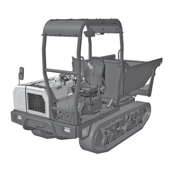
Controls and Components Name and Function of Controls FOPS (Roof) ROPS (Frame) Seat Idler Head Light Upper Roller Bumper Track Roller Track Sprocket Vessel (Bed) Engine Hood 36A3M-0201-010E -18-... - Page 27 Controls and Components 36A3M-0201-020E -19-...
- Page 28 Controls and Components Accelerator Lever ..This increases or decreases the engine speed. Drive Lever ... . . This is used when changing the direction of travel (FORWARD or REVERSE) or when turning the machine.
- Page 29 Controls and Components 14. Battery Cut Off Switch ..This switch cuts off the battery's negative terminal for service or long-term storage. 15. Emergency Switch ..Pressing this switch kills the engine in case of emergency. 16.
- Page 30 Controls and Components 23. Error Warning ... When this lights up, it indicates either the ECU or the engine itself has an error. 24. Overheat Warning ..This lights up when the engine coolant gets 120 degrees Celsius.
-
Page 31: Specifications
Specifications Product Specifications · Use this product properly after understanding its specifications thoroughly. CE (European) Models S300 Swivel Dump Model and Type Straight Dump (scoop bucket) Machine Mass 2470 2690 Maximum Payload kN(kgf) 29.4 (3000) Overall Length 3300 3675 Overall Width... - Page 32 Specifications S300 Model and Type Swivel Dump Straight Dump (Scoop Bucket) Gearshifting HST(2 speed modes) Travel Speed High Speed km/h 0 to 11 Low Speed km/h 0 to 6 Minimum Turning Radius approx. 2.3 (pivot turn) Gradability Degrees 25 (unloaded)
-
Page 33: Us Models
Specifications US Models S300 Swivel Dump Model and Type (scoop bucket) Machine Mass kg (lbs) 2690 (5930) Maximum Payload kN (lbs) 29.4 (6614) Overall Length mm (in) 3675 (144.7) Overall Width mm (in) 1620 (63.8) Overall Height mm (in) 2370 (93.3) - Page 34 Specifications S300 Model and Type Swivel Dump (Scoop Bucket) Gearshifting HST (2 speed modes) Travel Speed High Speed km/h (mph) 0 to 11 (0 to 6.8) Low Speed km/h (mph) 0 to 6 (0 to 3.7) Minimum Turning Radius m (ft) approx.
-
Page 35: Contents Of Tool Bag
Specifications Contents of Tool Bag Content Quantity Note Operator's Manual This Manual Engine Manual -27-... -
Page 36: Operation
Operation Preparation Pre-start up Inspection Always perform an inspection before use. Refer to Maintenance Schedule (page 51) for the inspection schedule and procedure. Checking and Filling Fuel • Keep fire and spark away when handling fuel. • Always stop the engine before refueling. •... -
Page 37: Adjusting Seat
Operation Turn the main switch to the [ (OFF)] Fuel Filler Cap position and remove the key. Put the fuel filler cap back and tighten it securely. Close the engine hood. Battery Cut Off Switch 36A3M-0401-020E Adjusting Seat • When adjusting the seat, make certain the seat is securely locked. Turning seat Pull up the seat lock lever to turn the seat. -
Page 38: Using Seat Belt
Operation Using Seat Belt • On the machine equipped with the ROPS, Always wear the seat belt. Thread the seat belt through the seat rail. Seat Belt Buckle Seat Rail Adjust the seat belt so that it holds the pelvis snuggly. - Page 39 This machine cannot perform adequately above that altitude. Using this machine under such conditions can result in an accident or cause damage to the machine. If you need to use this machine above that altitude, contact your CANYCOM representative. Make sure the parking brake switch [ Parking Brake Switch is pressed down.
- Page 40 Operation Make sure the emergency switch is in the Emergency Swtich RUN] position. If not, turn this switch to the right to the [ RUN] position. 36A3M-0401-030E Make sure the dump and swivel (Swivel Dump model) levers are in the neutral position and the lock plate is in the locked Dump Lever Swivel Lever...
- Page 41 Operation Turn the main switch to the [ (START)] position to start the engine. Once the engine starts, release the key immediately; switch will automatically return to the [ | (ON)] position. Start NOTE • Avoid frequent restarting. Once the engine 36A3M-0402-050E starts, run it for a while to charge the battery...
-
Page 42: Driving
Operation Driving • Do not allow bystanders to come near the machine when driving. • Always stay seated in the operator's seat when driving the machine. Never operate the drive lever off of the machine. This can cause the machine to run over or crush the operator. -
Page 43: Moving Forward
Operation M a k e c e r t a i n o f t h e s a f e t y o f y o u r Parking Brake Switch surroundings. H/L Speed Selector Turn parking brake switch to the [OFF] position. -
Page 44: Selecting Speed
Operation Selecting Speed H/L Speed Selector Push H/L speed selecter switch to either [ L (LOW)] or [ High (HIGH)] position to select the speed mode. This can be done while machine is in travel. 36A3M-0402-100E Turning Forward Move the left drive lever gradually forward to turn right. - Page 45 Operation 10. Move the right drive lever forward and left drive lever backward to make a quick turn left. Drive Lever 36A3M-0402-140E Turning Backward 11. Move left drive lever gradually backward to turn right backwards. Drive Lever 36A3M-0402-190E 12. Move the left drive lever backward and right drive lever foreward to make a quick turn right backwards.
-
Page 46: Stopping
Operation 14. Move the right drive lever backward and left drive lever foreward to make a quick turn left backwards. Drive Lever 36A3M-0402-120E Pivot Turning 15. Move the drive levers in opposite directions to make a turn on spot (pivot turn). Drive Lever 36A3M-0402-210E Stopping... -
Page 47: Parking
Operation Parking • Always park on a firm, level place. Never park on a potentially dangerous place. • Avoid parking on a slope. Never park on a slope with an incline of 15 degrees or steeper. If it is absolutely necessary to park the machine on a slope less than 15 degrees, make certain to apply parking brake firmly and block the tracks with chocks. -
Page 48: Emergency Stop
Operation Turn the main switch to the [ (OFF)] position and remove the key from the main switch. NOTE • Leaving the main switch in [ | (ON)] position drains the battery and cause it to discharge. 36A3M-0402-160E Emergency Stop Pushing the emergency switch kills the Emergency Swtich engine. -
Page 49: Working
Operation Working • Always make certain of the safety of your surroundings when dumping or swiveling bucket. • Never operate the dump or swivel lever off of the machine. This may cause the bucket to hit or crush the operator or bystander. •... -
Page 50: Swiveling Bucket
Operation Move the dump lever gradually toward Lock Plate the [ (DOWN)] position to lower bucket. When the bucket reaches its lower limit, a hissing noise is heard; move the dump lever back to the [ (NEUTRAL)] position. Down Flip the lock plate back in place to lock the Dump Lever dump lever. -
Page 51: Using Safety Prop
Operation Using Safety Prop • Place the safety prop under the bucket when inspecting or working under the bucket. • Make certain to undo the safety prop before lowering the bucket. Raise the bucket. Safety Prop Hold the bucket with the safety prop. 3670M-0403-050E -43-... -
Page 52: Operating Lcd
Operation Operating LCD Switches 36A3M-0405-010E DPF Switch ... . Pushing this begins DPF manual regeneration if the DPF Manual Regeneration Indicator is lit and the condition for regeneration is met. Maintenance Switch . -
Page 53: Contents Of Home Panel
Operation Contents of Home Panel 36A3M-0405-020E Oil Pressure Warning ..OFF while engine running: normal. Lights up while engine running: low engine oil pressure. Lights up while engine stopped: normal. Charge Warning ..OFF while engine running: normal. Lights up while engine running: charge error. - Page 54 Operation Overheat Warning ..Lights up when the engine coolant gets 120 degrees Celsius or above. Roll-over Warning ..Lights up when the machine rolls more than 27.5 degrees. Coolant Temperature .
-
Page 55: Maintenance Mode Panel
Operation Maintenance Mode Panel 36A3M-0405-031E How to Operate Press the left-most multifunction switch and the cursor switch DOWN to bring up the Maintenance Mode Panel. Complete (COMP) Switch . Use up/down cursor switch to highlight the message that is lit up. Then press this switch to turn off the highlight of the message. -
Page 56: Current Error Panel
Operation Current Error Panel Engine Vehicle ECU Display 36A3M-0405-040E How to Operate Press the cursor switch RIGHT to bring up (2)-2 previous errors panel/ Engine ....Displays Engine ECU errors. Vehicle . -
Page 57: Previous Error Log Panel
Operation Previous Error Log Panel Previous Error Logs in ascending order Only the previous ECU errorsare displayed. 36A3M-0405-050E How to Operate Press the cursor switch LEFT to bring up (2)-1 current errors panel/ Engine ....Displays Engine ECU errors. Vehicle . -
Page 58: Lcd Brightness Control
Operation LCD Brightness Control Brighter Darker 36A3M-0405-060E How to Operate With the Home Panel in the display, press the second-from the left multifunction switch to make the LCD brighter. Press the second-from-the-right multifunction switch to make the LCD darker. -50-... -
Page 59: Maintenance
• Perform a pre-startup inspection (PSI) before each use, a monthly inspection once a month, and a yearly inspection once a year. • Some maintenance procedures described below may require special knowledge or tools and instruments. Contact your CANYCOM representative to perform such procedures. Schedule... - Page 60 Maintenance Schedule Item Description Note There shall be no leak from fuel tank, √ √ √ injection pump, hosing, or plumbing. Fuel Fuel hose shall be free of damage or √ √ √ System deterioration. Fuel fil ter or fuel c oo l er sh a l l n o t be Cleaning: see Page 68 √...
- Page 61 Maintenance Schedule Item Description Note Coolant shall be clean and at the correct √ √ √ Cooling level. System Charge coolant. Battery electrolyte level shall be correct. √ √ Terminals shall be free of marked corrosion √ √ Battery and are tightly secured. Check battery electrolyte.
- Page 62 Maintenance Schedule Item Description Note Steel cord of the track shall not be cut or √ √ √ severely damaged. Track shall not be excessively worn, or √ √ √ deteriorated. There shall not be a big chunk Tracks of rubber missing. Steel core inside the track shall not be √...
- Page 63 Maintenance Schedule Item Description Note Shall work smoothly. √ √ √ There shall be no leaks when extending and √ √ contracting cylinder. Extend dump cylinder fully under load √ Hydraulic and hold. Stroke shall be within the range Cylinders specified by manufacturer.
- Page 64 Maintenance Schedule Item Description Note Seat shall be adjusted properly and shall be √ √ locked securely. Seat Mounting fasteners shall be secure and not √ √ √ missing. Warning labels and instruction plates shall be √ √ √ Labels clean, legible, and free of damage.
-
Page 65: List Of Fluids And Lubricants
Maintenance List of Fluids and Lubricants Item Schedule Grade Cap. Fuel As needed. Diesel Fuel (15.9 US gal) Engine Oil Fill Diesel Engine Oil Inspect daily. Fill as needed. API rating: CJ-4 9.5L Change JASO rating: DH-2 (10.0 US I n i t i a l l y - A f t e r 5 0 h o u r s o f u s e . SAE rating: 10W-30 Every 400 hours afterwards. -
Page 66: List Of Consumables And Spares
Maintenance List of Consumables and Spares • When replacing consumable or spare, always use CANYCOM genuine part. Item Part No. Schedule Qty. Engine Initially: 50 hours. Oil Filter Cartridge 16414-32434 Every 400 hours afterwards. 5229 0731 000 Every 2 years. - Page 67 Maintenance Item Part No. Schedule Qty. Ports to be connected T (H-Lo) Left Motor (Left) 5116 6136 000 T (H-Lo) Right Motor (Left) 3678 6224 000 Pump (Front) Motor (Left) 5229 6118 000 Pump (Rear) Motor (Right) 36A3 6108 000 Gear Pump Control Valve 36A3 6109 000...
- Page 68 Maintenance Item Part No. Schedule Qty. Dump Swivel Elbow Cylinder 3661 6177 000 Right Bottom Swivel Elbow Dump 3661 6177 000 Left Cylinder top Swivel Swivel Every 2 years or if defective. Cylinder Right Cylinder Left 3661 6168 000 Bottom Bottom Swivel Swivel...
-
Page 69: Engine
Maintenance Engine • Always stop the engine and remove the key before servicing. • An engine that has been running is very hot. Allow the engine to cool before servicing, or severe burns may result. • Keep fire and spark away when servicing the engine or handling fuel. Engine Oil •... - Page 70 Maintenance Visually inspect oil level. If it is below the lower limit, add oil. Lower Limit Upper Limit Visually inspect the condition of oil. If it is too dirty or viscosity is not normal, change oil. Put dipstick back in place. Dip Stick Close engine hood.
-
Page 71: Manual Dpf(Diesel Particulate Filter)Regeneration
Maintenance Manual DPF (Diesel Particulate Filter) Regeneration • Perform manual DPF regeneration in a well ventilated place. Running the engine and performing DPF regeneration emit carbon monoxide, and can cause carbon monoxide poisoning. • Make certain that there is no accumulation of flammable dust or debris on or around the exhaust system. - Page 72 Maintenance Press the parking brake switch [ON] and Parking Brake Switch move the lock lever to the [ (PARKING)] position. Lock Lever 36A3M-0402-010E Run the engine to raise the engine coolant temperature above 65 °C (149 °F). NOTE • DPF regeneration requires the engine coolant temperatur to be above 65°C (149°F).
-
Page 73: Fuel System
Maintenance When the DPF Service Indicator turns off, regeneration is done. DPF Service Indicator 36A3M-0504-090E Fuel System • Always stop the engine when servicing the fuel system. • Fuel is highly flammable. Keep fire and spark away when servicing the fuel system or handling fuel. -
Page 74: Draining Water Separator
Maintenance Open engine hood. Fill fuel. Push fuel priming pump by the fuel pump manually to bleed air. When the pump gets heavy, bleeding is complete. Close the engine hood. Priming Pump 36A3M-0505-010E Draining Water Separator NOTE • Water separator collects water and impurities in the fuel. When the red float in the water separator cup goes up, drain the water separator as described below. -
Page 75: Draining Water From Fuel Tank
Maintenance Draining Water from Fuel Tank • Keep fire and spark away when handling fuel. • When emptying the tank, use only the pump designed for diesel fuel. Wrong kind of pump can catch fire. • Dispose of the drained oil properly. Check the national and local regulations for discarding engine oil. -
Page 76: Fuel Filter Cartridge
Maintenance Fuel Filter Cartridge • Use only the genuine fuel filter. Non-genuine filter can damage the engine. Open the engine hood. Fuel Filter Cartridge Using an oil filter wrench, remove the fuel filter cartridge. 36A3M-0505-040E Apply a thin coat of new oil on the oil seal on the new fuel filter cartridge. -
Page 77: Hydraulic System
Maintenance Hydraulic System • Always stop the engine when servicing. • A machine that has been running is very hot. Allow the machine and oil to cool before servicing, or severe burns may result. Hydraulic Oil • When hydraulic oil level gets low, air can enter the hydraulic system and impairs its performance. - Page 78 Maintenance Visually inspect the oil level window for oil Oil Level Window level and condition. If the level is low, fill oil. HIGH If oil is dirty, change oil. Standard Level 36A3M-0506-070E Filling Remove four (4) M8 bolts to remove the Filler Cap pump cover.
-
Page 79: Suction Filter
Maintenance Suction Filter NOTE • Change suction filter when changing hydraulic oil. Drain oil. Suction Filter Mount Loosen hose bands and remove hoses. Suction Filter Remove bolts on the flange to remove the suction filter mount. Remove the suction filter element from the filter mount. -
Page 80: Drive Train
Maintenance Apply a thin coat of new oil on the oil seal on the new fuel filter cartridge. Install the new cartridge. Start the engine and run a while to Filter cartridge circulate oil. Stop the engine to check oil level. If it is low, fill. - Page 81 Maintenance • When loosening track adjuster valve, loosen slowly and gradually so that it will not come off. Track adjuster cylinder is under pressure, and if adjuster valve comes off, it may be projected out, possibly causing injury or damage. •...
- Page 82 Maintenance Remove track adjuster valve cover. Inspect the gap between track and track roller ( A ) to be between 30 and 40 mm (1.2 and 1.6 in). If the gap (A) is wider (the track is too loose), attach a grease pump to track adjuster valve nipple and pump grease into track adjuster Track cylinder until the gap is within the specified...
-
Page 83: Travel Motor Oil
Maintenance 10. Adjust the track tension. 11. Remove grease pump, install valve cover, and lower the machine. Travel Motor Oil • Always park machine on a level surface and block tracks with chocks when working under machine. • Dispose of the drained oil properly, according to the national and local regula- tions. -
Page 84: Greasing
Maintenance Greasing • Follow the maintenance schedule (every 100 hours, more often in a severe work ing environment) to grease the machine. Lack of greasing may result in rust, excessive wear or seizure. NOTE • When using a manual grease gun, pump 5-6 times. When the handle of the gun becomes heavy, stop pumping immediately. -
Page 85: Drive Lever Neutral
Maintenance Drive Lever Neutral Link Arm Hydraulic Pump Link Arm Rod A 36A3M-0507-070E Remove one end of the rod A from the link arm. Adjust it so that both of the link arms are vertical. Remount the removed end of the rod A to the link arm. Arm A Arm B Rod B... - Page 86 Maintenance After above 3 through 7 is done, move the both drive levers forward to the limit and see if the arms A and B move forward by the same angle. If the angles are different, adjust the rod B or C so that they are the same. Once above 3 through 7 is complete, start the engine and see if the machine does not move.
-
Page 87: Electrical System
Maintenance Electrical System • Always stop the engine and turn the main switch to [ (OFF)] position, and disconnect the negative (-) terminal of battery when servicing the electrical system. • Do not work on the electrical system with wet hands. Electric shoc can result. Battery •... - Page 88 Maintenance • Never fill battery fluid beyond the [UPPER LEVEL] line. Battery fluid can spill and cause damage to the machine or personal injury. • Always remove the battery from the machine before charging. Failure to do so can cause damage to the electrical components and wiring. •...
-
Page 89: Fuses
Maintenance Remove all the battery filler plugs. Follow the instructions in the battery charger user's manual to charge the battery. ‑ When the battery is fully charged, put the filler plugs back in place. U P P L E V Reinstall the battery, attach the electrical cables in the reverse order of removal. - Page 90 Maintenance Locate the blown fuse and replace it with a new one of the correct rating. Put the lid back in place. Close the engine hood. 36A3M-0508-090E NOTE • Key Switch, EGR, Engine ECU, Vehicle ECU: 5A • Lights and Horn, H/L Speed Valve and Parking Brake Valve, Accessory Outlet, Optional Power: 10A •...
-
Page 91: Cooling System
Maintenance Cooling System Engine Coolant • Do not open the radiator cap when the engine is still running or right after it has stopped. The cooling system is hot and under pressure, so opening the cap when they are still hot can release boiling coolant and cause severe burns. Wait for the engine to cool after stopping (about 30 minutes) before opening. - Page 92 Maintenance Changing Have an approproate drain pan big enough to hold all the coolant. NOTE • Coolant grade and amount: see Page 57. Open the coolant drain cock at the bottom of the radiator to drain coolant. Radiator Cap Open the engine hood. Remove the radiator cap and wash inside the radiator with running water.
-
Page 93: Cleaning, Replacement, Adjustment
Maintenance Cleaning, Replacement, Adjustment Air Cleaner Element • Clean air cleaner element regularly. Dirty cleaner element reduces engine performance and life. • Do not hit the air cleaner element hard. The element can be deformed. • Replace air cleaner element if damaged. Inspecting/Cleaning Engine Hood Open the engine hood. -
Page 94: Oil Filter Cartridge
Maintenance Install a cleaned or new air cleaner element. Make sure that it seats snuggly to the housing. Hold it with the air cleaner lid and close the spring hooks. Close the engine hood. Oil Filter Cartridge Remove the oil filter cartridge with a filter wrench. -
Page 95: Fan Belt
Maintenance Fan Belt • Always stop the engine and remove the key before servicing. A moving fan or belt can cause injury. • An engine that has been running is very hot. Allow the engine to cool before servicing, or severe burns may result. •... -
Page 96: After Use Care
Maintenance After Use Care • Do not wash the engine, control panel, electrical parts, or tank caps with air breather with running water; water may enter inside and cause rust or damage. • Clean the machine after use; leaving dirt or foreign objects may cause damage. •... -
Page 97: Washing
Maintenance Washing • High-pressure washer can be dangerous. Never point it to a person. Make sure no one is behind the machine when washing the machine with a high-pressure washer. Follow the instruction manual of the high-pressure washer and familialize with its use. •... -
Page 98: Storage
Maintenance Storage • Fire hazard; do not store the machine where there is a possiblity of ignition. • Do not wash the engine or control panel with running water; water may enter inside and cause rust or damage. • Clean the machine before storage; leaving dirt or foreign objects may cause rust or damage. -
Page 99: Troubleshooting
Troubleshooting chart below. If the malfunction or abnormal condition is not listed in the chart, or the suggested measure does not solve the problem, consult with your CANYCOM representative. • Some corrective measures listed below require special knowledge and/or equipment. - Page 100 Area Malfunction Possible Cause Corrective Measure Ref. Out of fuel. →Fill fuel. Page 28 →Please contact Piston seizure due your CANYCOM to insufficient or Engine stops representative. bad oil. abruptly →Please contact Other (other than your CANYCOM the above). representative.
- Page 101 →Fill coolant. Insufficient amount Page 83 of coolant. Engine overheats →Clean. Radiator is clogged or blocked. →Please contact Other (other than your CANYCOM the above). representative. →Please contact your CANYCOM Leak in the fuel representative for system. a repair. Excessive fuel →Clean or replace...
- Page 102 Drive Train section corresponding system. position. →Please contact Other (other than your CANYCOM the above). representative. →Please contact Irregular noise or your CANYCOM heat is observed at representative. or around the track. →Refer to the Problem in "Hydraulics"...
- Page 103 Corrective Measure Ref. Not properly →Adjust. Page 73 adjusted. Track does not →Please contact move smoothly. Other (other than your CANYCOM the above). representative. Track is loose. →Adjust. Page 73 →Put it back and Track is derailed. adjust its tension →Tighten.
- Page 104 →Refer to the Engine is Operator's Manual overheating. for the engine. Overheat warning stays on after the →Please contact engine starts. Other (other than your CANYCOM the above). representative. Safety Blown fuse. →Replace. Page 82 Charge warning Devices →Please contact...
-
Page 105: Transporting
Transporting Hauling Loading and Unloading •Park the transporter (truck) on a level ground and apply parking brake. Always use chocks to secure wheels. •Do not allow bystandars to come close to the machine or the transporter when loading or unloading the machine. •Use only the loading ramps with suffient strength(to withstand the combined weight of the machine and the operator), width (more than 1.2 times the width of the track), and length (more than 4 times the height of the bed of the... - Page 106 Transporting Height 36A3M-0701-010E Loading to the Transporter 1. Park the transporter and apply parking brake. Secure the wheels with chocks. 2 . Place the loading ramps. Secure the hooks of the ramps firmly and flush with the bed of the transporter. 3. Set the H/L Speed Selecter switch to [ (LO)] mode and drive the machine slowly forward onto the bed of the truck.
-
Page 107: Hoisting And Towing
Transporting Hoisting and Towing Hoisting • Hoisting requires qualifications. Check with your local authority for necessary qualifications and licenses for hoisting. • Use hoisting sling of sufficient strength. Always use the slings of the same length when more than one is used. •... -
Page 108: Towing
Transporting Towing 1. With the engine running, this machine can be towed when the parking brake is turned to the [ (OFF)] position and the lock lever is moved to the [ (Drive)] position. (See Driving, page 29) When Machine Cannot be Towed Parking Brake Release Ports Remove the back cover on the HST motor. - Page 109 NOISE LEVEL(ISO 6395:2008,ISO 6396:2008) Model Engine Type Type Speed rpm 86 dB (A) S300 Kubota V2403 2400 rpm 101 dB (A) VIBRATION(ISO 5349:2001,ISO 2631:1997) Vibration Model Engine Speed Steering lever Seat 2.3 m/s 0.6 m/s S300 2700 rpm (uncerfainty K=0.45m/s...
- Page 110 90-1 Fukumasu, Yoshii-machi, Ukiha-shi, Fukuoka, Japan 839-1396 Sales Headquarters TEL +81-(0)943-75-2195 FAX +81-(0)943-75-4396 Authorized Dealer All rights reserved. Unauthorized use or reproduction of this material is prohibited.
Need help?
Do you have a question about the S300 and is the answer not in the manual?
Questions and answers