Table of Contents
Advertisement
Quick Links
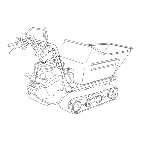
Off-road Rubber Track Carrier
SC45
Operator's Manual
Read this manual completely before operating or maintaining this machine.
Failure to follow safety precautions could result in serious injury or death.
Keep this manual for future reference by you and by all those who operate
and maintain this machine.
3577 6107 000
Advertisement
Table of Contents

Related Manuals for CanyCom SC45


Summary of Contents for CanyCom SC45
- Page 1 Off-road Rubber Track Carrier SC45 Operator's Manual Read this manual completely before operating or maintaining this machine. Failure to follow safety precautions could result in serious injury or death. Keep this manual for future reference by you and by all those who operate and maintain this machine.
- Page 2 CHIKUSUI CANYCOM, INC. http://www.canycom.jp/ 90-1 Fukumasu, Yoshii-machi, Ukiha-shi, Fukuoka, Japan 839-1396 Sales Headquarters (International) TEL +81-(0)943-75-2195 FAX +81-(0)943-75-4396 Authorized Dealer All rights reserved. Unauthorized use or reproduction of this material is prohibited.
- Page 3 Notice to Users and Maintenance Personnel Thank you for purchasing this machine. This manual provides information needed for safe and effective use of this machine to those who operate or maintain this machine. Make sure to read and understand this manual thoroughly before operating this product.
- Page 4 Notice to Owner • Be sure that everyone who uses this machine, including those who rent or lease this machine, receives a copy of this Operator's Manual and understands the importance of reading and following the information in this manual. Warning Terms Used in this Manual In this manual, the following four warning terms are used to signal the four levels of hazard (or seriousness of possible accidents).
- Page 5 Warranty and After-Sales Service Warranty CHIKUSUI CANYCOM, INC. provides a warranty through your local CANYCOM dealer. A copy of this warranty is attached to the back of this manual. After-Sales Service Consult your local CANYCOM dealer or our company’s sales department regarding service orders or any questions or problems that may arise when using this machine.
- Page 6 Emission Control Information This product meets the applicable emissions and evaporative regulations as required by the United States Environmental Protection Agency or the California Air Resources Board. The relevant information is provided in the label shown below. Location of Emissions Label Emissions Label Month and Year of Manufacture THIS EQUIPMENT...
-
Page 7: Table Of Contents
Contents 1. Safety Safety Labels ........1 Safety Precautions . - Page 8 Driving ........16 Starting .
- Page 9 Drive Train ........39 Track.
- Page 10 Warranty Warranty Certificate is attached at the end of this manual. * Have the warranty certificate signed and sealed after you have received and fully understood the instructions for handling this machine and received the receipt. Appendix • Operator's Manual for the Engine * Be sure to read and understand it together with this manual .
-
Page 11: Safety
• Replace these labels immediately if they have been removed, have fallen off or become illegible. Use the part number, on the label or shown in this manual, to order a replacement label from your CANYCOM representative. 3573 6061 000... -
Page 12: Safety Precautions
Safety Safety Precautions This section contains safety precautions to follow when operating and maintaining machine. Read and understand the precautions in this section as well as throughout this manual and follow them when operating or maintaining machine. Failure to follow safety precautions could result in property damage, serious injury or death to the operator or bystanders. -
Page 13: Preparation
Safety Preparation • Always wear protective footwear, long trousers, hardhat, safety glasses and ear protection when operating or servicing machine. Proper clothing will minimize the chance of injury. Do not operate machine if you have long hair, loose clothing, or jewelry; all of which can get tangled in moving parts. Do not operate machine barefoot or with open sandals. - Page 14 Safety General Driving • Do not operate engine in a confined space where dangerous carbon monoxide fumes can accumulate. • Do not touch engine, muffler or exhaust pipe while engine is running or soon after it has stopped. These areas will be very hot and can cause burns. •...
- Page 15 Safety • On a slippery surface, travel slowly and exercise caution to reduce the chance of skidding or sliding out of control. Never operate on ice. • Always make certain that there is no obstacle or person behind machine when backing up.
- Page 16 Safety • Never drive on a slope that you are not comfortable with. Avoid a slope that is so rough, slippery, or loose that you feel like machine could tip over. • When driving down a slope, stop and shift to lowest gears (auxiliary transmission in Low).
- Page 17 Safety Loading and Driving with a Load • The maximum payload for SC 45 is 992lb (450kg). Do not exceed this maximum payload under any circumstance. • Do not operate on a slope steeper than 20 degrees. Do not carry more than 496lb (225kg) with SC 45 when operating on a slope between 15 and 20 degrees.
-
Page 18: Servicing
Safety Parking • Park machine on a flat, level and stable surface. Do not park in a dangerous place. Never park machine on a slope steeper than 15 degrees. Avoid parking on a slope less than 15 degrees. If parking on a slope less than 15 degrees is unavoidable, block tracks at the lower end of machine. -
Page 19: Controls And Components
Controls and Components Name and Function of Controls Front Rear 3577M-6107-0201-010 1 Throttle Lever ... . Throttle Lever is used to control engine speed. 2 Drive Clutch Lever ..Drive Clutch Lever is used to engage or disengage drive clutch. - Page 20 Controls and Components 6 Starter Handle... . Starter Handle is used to start engine. 7 Fuel Valve Lever ..Fuel valve lever opens or shuts fuel flow. 8 Shift Lever.
-
Page 21: Specifications
Specifications Product Specifications · Use this product properly after understanding its specifications thoroughly. SC 45 Model and Type One-way dump 220 (485) Machine Mass kg (lbs) Maximum Payload kN (kg) 4.41 (450) 2080 (81.89) {1970 (77.56)} Overall Length mm (in) Overall Width 740 (29.13) mm (in) - Page 22 Specifications SC 45 Model and Type One-way Dump Forward 1st km/h (mph) 0.5 (0.3) Forward 2nd km/h (mph) 0.8 (0.5) Forward 3rd km/h (mph) 1.4 (0.9) Forward 4th km/h (mph) 2.0 (1.2) Speed Forward 5th km/h (mph) 3.3 (2.1) Forward 6th km/h (mph) 5.3 (3.3) Reverse 1st...
-
Page 23: Contents Of The Tool Bag
Specifications Contents of the Tool Bag Content Quantitiy Note Operator's Manual This Manual Operator's Manual for the Engine Engine Service Tool for Servicing the Engine -13-... -
Page 24: Operation
Operation Preparation Pre-start up Inspection Always perform an inspection before use. Refer to "Maintenance Schedule" (page 29) for the inspection schedule and procedure. Checking and Filling Fuel • Keep fire and spark away when handling fuel. • Always stop engine before refueling. •... -
Page 25: Adjusting Handle Lever Angle
Operation Adjusting Handle Lever Angle • Set handle lever to a proper position. Improperly adjusted handle bar can cause an accident. • Pinch hazard. Make certain that hands or fingers are not in the way to be caught when adjusting handle lever. •... -
Page 26: Driving
This machine cannot perform adequately above that altitude. Using this machine under such conditions may result in an accident or cause damage to machine. If you need to use this machine above that altitude, contact your CANYCOM representative. Make sure drive clutch lever is in [Stop] position. - Page 27 Operation Make sure shift lever is in [N (neutral)] position. Shift Lever 3575M-0402-020E Open fuel valve lever. Fuel Valve Lever 3577M-6107-0402-030 Move choke lever to [Close] position. NOTE Choke Lever • It is not necessary to close the choke valve when engine is already warm.
- Page 28 Operation Press down main switch and turn it to (run)] position until it locks in that position. Main Switch 3573M-0402-010US Pull starter handle rapidly to start engine. When engine starts, return handle gently 3583M-0402-060US Once engine starts, return throttle lever to Throttle Lever [Slow] position.
-
Page 29: Driving
Operation Driving • Do not allow bystanders to come near machine when driving. • Set handle lever in a proper position for the operator. Setting them in an improper position may hinder safe operation. • Always make certain of the safety of your surroundings before driving; start slow. - Page 30 Operation • Pinch hazard. Make certain that hands or fingers are not in the way to be caught when operating clutch lever. Make certain of the safety of your surround- ings. Stop Make certain that drive clutch lever is in [Stop] position.
- Page 31 Operation Move drive clutch lever to [Run] position to start. Drive Clutch Lever 3577M-6107-0402-130 Grasp left side clutch lever to turn left. Left Turn (Forward) Side Clutch Lever (Left) Left Turn (Backward) 3577M-0402-142US Grasp right side clutch lever to turn right. Right Turn (Forward) Side Clutch Lever(Right) Right Turn (Backward)
-
Page 32: Stopping
Operation Stopping • Do not make a sudden stop. The machine may skid or tip over. • Always park on a firm, level place. Never park on a potentially dangerous place. Move throttle lever toward [Slow] position to slow down. Throttle Lever Fast Slow... -
Page 33: Shifting
Operation Shifting • Always stop machine to shift gears. • Always shift gears firmly. When transmission is not firmly shifted, it may jump out of gear, resulting in loss of control of machine. Stop machine. High Move shift lever or auxiliary (aux.) shift lever Shift Lever firmly into a desired position. -
Page 34: Parking
Operation Parking • Always park on a firm, level ground. Never park on a potentially dangerous place. • Avoid parking on a slope. Never park on a slope with an incline of 15 degrees or steeper. If it is absolutely necessary to park machine on a slope less than 15 degrees, make certain to apply parking brake firmly and block tracks with chocks. -
Page 35: Working
Operation Close Fuel Valve Lever. Fuel Valve Lever NOTE • Carbon deposit tends to accumulate on spark plug when running engine at low engine speed. When engine has been run at low engine speed for an extended period, run engine at high engine speed for a while 3577M-6107-0402-210 before stopping engine to burn off carbone deposite. - Page 36 Operation Turn lock plate so that dump lever can be Lock Plate operated. 3577M-6107-0403-010 Raising using Deck Lever Dump Lever Move dump lever up to raise loading deck. When loading deck reaches its upper limit, a hissing noise is heard; move dump lever back to [ (neutral)] position.
- Page 37 Operation Lowering using Handlebar Lever Move dump lever down to lower loading deck. When loading deck reaches its lower limit, a hissing noise is heard; release dump lever. It automatically returns to neutral position. Down Dump Lever 3577M-0403-080US Turn lock plate back in place to lock dump Lock Plate lever.
-
Page 38: Using Safety Lock Plate
Operation Using Safety Lock Plate • When it is necessary to inspect or work under loading deck, raise loading deck to do so. Never work under loading deck when it is in the dumping position. • Hold loading deck in the raised position with safety lock plate when inspecting or working under loading deck. -
Page 39: Maintenance
Clean and adjust spark plug Check and adjust valve clearance Clean cylinder head Clean carburator Lap intake and exhaust valves Replace fuel hose Every three years (or as needed) Overhaul : for items maked with this symbol, please consult with your CANYCOM representative. -29-... -
Page 40: Chassis
• Perform a pre-startup inspection (PSI) before each use, a monthly inspection once a month, and a yearly inspection once a year. • Some maintenance procedures described below may require special knowledge or tools and instruments. Contact your CANYCOM representative to perform such procedures. Schedule Item... - Page 41 Maintenance Schedule Item Description Note Rods, links, and wires in linkage shall be free √ √ √ of deformation or damage. Linkage Connections shall be free of looseness, √ √ √ excessive play, or missing cotter pins. Shall be free of cracks, deformation, or √...
-
Page 42: List Of Fluids And Lubricants
Maintenance Schedule Item Description Note Shall work smoothly. √ √ There shall be no leaks when extending and √ √ contracting cylinder. Extend cylinder fully under load and hold. √ Hydraulic Stroke shall be within the range specified by Cylinder manufacturer. -
Page 43: List Of Lubricants
Maintenance List of Lubricants Lubrication Area Schedule Grade Linkage for transmission lever Every 6 months Chassis Grease Fulcrum point for dump device *2 Every 6 months Chassis Grease Transmission Oil Both end of hydraulic cylinder (above and bottom) Every 6 months API : GL4 or GL5 SAE : #80 -33-... -
Page 44: List Of Consumables And Spares
Maintenance List of Consumables and Spares • When replacing a consumable or spare, always use the CANYCOM genuine part. Item Part No. Schedule Qty. Engine Air Cleaner Element 17210-ZE1-822 Replace if defective. Spark Plug (NGK BPR6ES) 98079-56876 Replace if defective. -
Page 45: Removing And Installing Body Panels
Maintenance Removing and Installing Body Panels • Cut or pinch hazard exists when removing or installing body panels; beware of sharp edges and pinch points. • Make certain to reinstall panels after removing for repairs or inspection. Fender Removing Remove two screws that secure fender. Screw Remove fender. -
Page 46: Engine
Maintenance Engine • Always stop engine before servicing. • Allow engine to cool off before servicing. Engine is very hot after operation and may pose a burn hazard. • Keep fire and spark away when handling fuel. Engine Oil • Dispose of drained oil properly. •... -
Page 47: Air Cleaner
Maintenance Filling Oil Filler Cap Remove oil filler cap. Follow the instructions in "Operator's Manual for the Engine" to fill oil. Check oil level. Screw oil filler cap firmly back in place. 3577M-6107-0505-010 Changing Drain Plug Have an appropriate oil drain pan. Raise loading deck and set safety lock plate Remove oil drain plug and drain oil. -
Page 48: Spark Plug
Maintenance Spark Plug • When removing spark plug cap, do not pull cable; pull plug cap. Pulling cable can damage the conductor or the joint of cable. • Replace spark plug if damaged. Remove spark plug cap and spark plug. Follow the instructions in "Operator's Manual for the Engine"... -
Page 49: Drive Train
Maintenance Drive Train • Stop engine when servicing drive train. • Allow machine to cool off before servicing. Engine is very hot after operation and may pose a burn hazard. Track • Jack up machine securely when inspecting and adjusting track. Jack it up on a level ground. -
Page 50: Transmission Oil
Maintenance Adjusting Track Tension Bolt Jack up machine so that it is parallel to the Lock Nut ground. Loosen lock nut under machine. Adjust track tension bolt so that the clear- ance between track and center roller (clear- ance A) at the furthest is between 10 and 15mm. -
Page 51: Drive Belt
Maintenance Remove filler plug. Fill specified oil into filler. Filler Plug Install filler plug. Install fender. 3577M-0506-030US Drive Belt • Adjust belt tension properly. Inproperly tensioned belt may reduce performance and its service life. Remove fender. Adjust Nuts Move clutch lever to [Run] position. Inspect drive belt tension. -
Page 52: Parking Brake
Maintenance Parking Brake • Always keep brake adjusted for maximum performance. Improperly adjusted brakes may result in property damage, serious injury, or death. Remove fender. Adjust Nuts Spring Move drive clutch lever to [Stop] position. Inspect that the amount of stretch on brake spring is 3-4 mm. -
Page 53: Side Clutch
Maintenance Side Clutch Raise loading deck and support it with loading deck safety lock plate. Adjust side clutch with adjust nut so that the play on side clutch lever is between 1 and 5 Undo safety lock plate and lower loading deck. -
Page 54: Hydraulic System
Maintenance Hydraulic System • Stop engine when servicing drive train. • Allow machine to cool off before servicing. Engine is very hot after operation and may pose a burn hazard. Hydraulic Package • Make certain to fill hydraulic package with specified fluid to the specified level. Insufficient amount or wrong grade of fluid reduces performance and may cause permanent damage to engine. -
Page 55: Hydraulics Belt
Maintenance Filling Remove filler cap. Fill fluid. Filler Cap Put filler cap back in place firmly. Run engine for a while to circulate hydraulic fluid. 3577M-0507-020US Hydraulics Belt • Adjust belt tension properly. Inproperly tensioned belt may reduce performance and its service life. Inspecting Remove belt cover. -
Page 56: Loading Deck
Maintenance Loading Deck Lubrication • Follow the maintenance schedule to lubricate machine. Lack of lubrication may result in rust, excessive wear or seizure. NOTE • When using a manual grease pump, push handle five to six times. When handle becomes heavy, stop pushing. •... -
Page 57: After Use Care
Maintenance After Use Care • Do not wash engine, control panel, electrical parts, or tank caps with air breather with running water; water may enter inside and cause rust or damage. • Clean machine after use; leaving dirt or foreign objects may cause damage. •... -
Page 58: Storage
Maintenance Storage • Fire hazard; do not store machine where there is a possiblity of ignition. • Do not wash engine or control panel with running water; water may enter inside and cause rust or damage. • Clean machine before storage; leaving dirt or foreign objects may cause rust or damage. -
Page 59: Troubleshooting
Troubleshooting chart below. If the malfunction or abnormal condition is not listed in the chart, or the suggested measure does not solve the problem, consult with your CANYCOM representative. • Some corrective measures listed below require special knowledge and/or equipment. - Page 60 Choke lever is in [Close] →Move choke lever to Page 19 position. [Open] position. Engine stalls. Other (other than the →Please contact above). your CANYCOM representative. Out of fuel. →Fill fuel. Page 14 Other (other than the →Please contact Engine stops abruptly. above).
- Page 61 →Clean or replace air Page 39 Black smoke comes out cleaner element. of exhaust Other (other than the →Please contact above). your CANYCOM representative. Engine Bad fuel. →Change fuel. Wrong engine oil. →Change oil. Page 38 White or blue smoke Other (other than the →Please contact...
- Page 62 Improperly adjusted side →Adjust side clutch Page 43 clutch. Machine does not turn Other (other than the →Please contact smoothly. above). your CANYCOM Drive Train representative. Irregular noise or →Please contact abnormal heat from your CANYCOM roller, sprocket, or idler. representative.
-
Page 63: Transporting
Transporting Hauling Loading and Unloading • Park transporter (truck) on a level ground. Always use chocks to secure wheels. • Do not allow bystandars to come close to machine or transporter when loading or unloading machine. • Use only the loading ramps with sufficient strength (to withstand the combined weight of machine and operator), width (more than 2 times the width of track), and length (more than 4 times the height of loading deck of transporter), and have anti-slip ramp surfaces. - Page 64 Transporting Height 3577M-0701-010US Park transporter on level ground. Secure wheels with chocks. Place loading ramps. Secure hooks of ramps firmly and flush with loading deck of transporter. Drive machine slowly forward onto loading deck. Park machine according to the instructions in "Parking" (page 24). Secure machine firmly to loading deck of transporter with tie-down belts, rope, or wire.
Need help?
Do you have a question about the SC45 and is the answer not in the manual?
Questions and answers