Table of Contents
Advertisement
Quick Links
Advertisement
Table of Contents

Related Manuals for Circontrol Raption 200


Summary of Contents for Circontrol Raption 200
- Page 1 Raption 200 Installation Manual...
- Page 2 THIS PAGE HAS BEEN INTENTIONALLY LEFT BLANK...
- Page 3 C O P Y R I G H T I N F O R M AT I O N This document is copyrighted, 2023 by Circontrol, S.A. All rights are reserved. Circontrol, S.A. reserves the right to make improvements to the products described in this manual at any time without notice.
-
Page 4: Table Of Contents
1 — So, Hello! 2 — Before the installation A - Important safety instructions B - Electrical wiring considerations C - Important Electrical Safety Instructions D - EVSE Classification E - Storage F - Unloading and handling 3 — Dimensions and overview A - Dimensions of Dispenser B - Overview of Dispenser C - Dimensions of Power Unit... - Page 5 Here’s your guide to install your Raption 200 4 — Installation A - Minimum distances of Dispenser B - Minimum distances of Power Unit C - Minimum distances between Power Units D - Fixing 5 — Wiring A - Power Unit...
- Page 6 It is mandatory to follow the basic security information supplied in this manual to ensure safe and proper installation. Failure to follow safety instructions may involve personal injury, equipment damage and danger of death. CIRCONTROL is not responsible for events arising from such breach. THE FOLLOWING SYMBOLS ARE USED FOR IMPORTANT...
-
Page 7: So, Hello
So, hello! • Compliant with IEC 61851; Electric vehicle conductive charging system (IEC 61851-1, IEC 61851-21-2 and IEC 61851-23). • Compliant with IEC 62196, Plugs, sockets-outlets, vehicle connectors and vehicles inlets, Conductive charging of electric vehicles (IEC 62196-1 and IEC 62196-3). •... - Page 8 • Do not use this unit for anything other close...). than electric vehicle charging modes are expected in IEC 61851-1. • Use only Circontrol supplied spare parts. • Do not modify this unit. If modified, CIRCONTROL will reject all • Do not use this unit if the enclosure...
-
Page 9: Before The Installation
Before the installation Electrical wiring considerations Take into consideration this section before start wiring connections of the Charge Point. 1 - I N P U T P O W E R S U P P LY The input power supply line for the Charge Point must be hardwired from a dedicated power transformer or generator and not by LV overhead power lines. -
Page 10: C Important Electrical Safety Instructions
Raption 200 Installation Manual Important Electrical Safety Instructions Read carefully all the instructions before starting in order to ensure properly handling of electrical parts. A safe work environment is not enough to control all potential electrical hazards. It is recommended to be very cautious and work safely. So, the safety rules shown below could help to control risks of injury or death from workplace hazards. -
Page 11: Devse Classification
EVSE Classification Classification of the unit according to the IEC 61851-1:2017: 1 — Power supply Input • EV supply equipment connected to AC supply network • Permanently connected 2 — Power supply Output • DC EV supply equipment 3 — Environmental conditions •... -
Page 12: E - Storage
Raption 200 Installation Manual Storage Whenever possible, the Charge point must be unloaded in their place of installation and operation. In case of unloaded to a temporary location for storage, it is convenient to not remove the packaging and store them meeting the following minimum requirements: •... -
Page 13: F Unloading And Handling
Unloading and handling All processes of unloading and handling of the Charge Point must be executed and monitored by qualified personnel attending to the significant weight of the unit, complying with safety rules and using the appropriate points of support. Important notes: •... - Page 14 Raption 200 Installation Manual Dimensions of Dispenser necessary space for charging cables necessary space for charging cables Units specified in millimetres...
-
Page 15: Dimensions And Overview
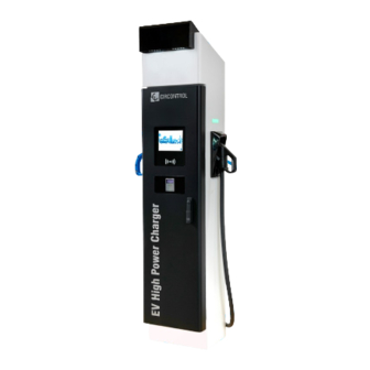
Dimensions and Overview Overview of Dispenser 1 — Cover 2 — Courtesy Lights 3 — Screen 4 — CCS/CHA plug 5 — Emergency button 6 — RFID Reader 7 — Locking handle 8 — Decorative front panel 9 — Antenna 10 —... -
Page 16: C Dimensions Of Power Unit
Raption 200 Installation Manual Dimensions of Power Unit Units specified in millimetres Note: - It is also mandatory to install upstream the Charge Point a non included AC Power Unit with all protections, more details in Chapter 5. -
Page 17: D Overview Of Power Unit
Overview of Power Unit 1- Unit air inlet 2- Locking handle 3- Emergency button 4- Decorative front 5- Unit air outlet 6- Decorative rear panel panel... -
Page 18: E Dispenser Opening
Raption 200 Installation Manual Dispenser opening Step 1 It is placed a locking handle in the middle front part of dispenser. Follow the steps in order to unlock and open it: Step 2 1- Insert the key supplied in the lock and turn it 90 °... -
Page 19: F Power Unit Opening
Power unit opening It is placed a locking handle in both front and rear power unit doors. R E A R D O O R Step 1 F R O N T D O O R Step 1 Step 2 Step 2 Step 3 Follow the steps in order to unlock and open it:... -
Page 20: G Placing
Raption 200 Installation Manual Placing In order to place the Charge Point in its final location, please follow the next steps: 1 — R E M O V I N G T H E C H A R G E P O I N T F R O M PA L L E T The Charge Point is mounted on a pallet so as to do a safe transport. - Page 21 • For Power Unit: Step 2 Step 1 Steps: 1- Pull outwards the 4 corners installed in the lower part of the Power Unit. No tools needed. 2- Remove the screws of front panel using a Phillips screwdriver. Locate the screws that are fixing the pallet and remove them with a spanner tool.
- Page 22 Raption 200 Installation Manual 2 — P L AC I N G T H E D I S P E N S E R I N T H E F I N A L L O C AT I O N...
- Page 24 Raption 200 Installation Manual 3 — P L AC I N G T H E P O W E R U N I T I N T H E F I N A L L O C AT I O N Once the Power Unit is free from the pallet, the only way to move the charger is with forklift.
- Page 25 THIS PAGE HAS BEEN INTENTIONALLY LEFT BLANK...
- Page 26 Raption 200 Installation Manual When installing the Dispenser or Power Unit, respect the minimum distances space for maintenance and safety reasons. Please comply accordingly to your country specifications. The next picture shows how it should be installed. • Do not install near areas where water or fluids can penetrate into the unit.
-
Page 27: Installation
Installation Minimum distances of Power Unit Units specified in millimetres Notes: - Respect the minimum frontal and rear distance to allow proper circulation of air flow. This unit has forced ventilation. - If Bollard Impact Protector is installed, keep 800 mm as a minimum distance in order to give enough space to open the frontal door of the Charge Point for maintenance tasks. - Page 28 Raption 200 Installation Manual Minimum distances between Power Units If necessary to have more than one power unit, they can be installed side by side to minimise the space. Respect frontal and rear minimum distance in order to allow proper circulation of air flow.
- Page 29 Fixing The purpose of this chapter is the technical definition and basic requirements for implementing the base and fixing the Charge Point. • The unit is adequate for indoor and outdoor installation • It is shown two different options to install the Charge Point: using the provided foundation kit or using a non included injection mortar.
- Page 30 Raption 200 Installation Manual F O U N DAT I O N T E M P L AT E F O R D I S P E N S E R Place the foundation bolts into the templates using provided nuts with the help of a 24mm open-end wrench.
- Page 31 D I S P E N S E R T E M P L AT E D I M E N S I O N S TEMPLATE LOWER AND UPPER PART Units specified in millimetres...
- Page 32 Raption 200 Installation Manual C O N C R E T E B A S E M E N T F O R D I S P E N S E R Before fixing the template inside of the concrete basement make sure front mark must face with the front side of the Charge Point.
- Page 33 Units specified in millimetres...
- Page 34 Raption 200 Installation Manual DISPENSER FOUNDATION MEASUREMENTS ORIENTATIONAL FOUNDATIONS FOR RAPTION 200 DISPENSER TYPE OF TERRAIN FOUNDATION SIZE COMMENTS (kg/cm (Az x Bz x Hz) cm SOFT 65 x 65 x 65 For example vegetal not compact terrain COMPACT 55 x 55 x 55...
- Page 35 F O U N DAT I O N T E M P L AT E F O R P O W E R U N I T • Place the foundation bolts into the templates using provided nuts with the help of a 24mm open-end wrench.
- Page 36 Raption 200 Installation Manual P O W E R U N I T T E M P L AT E D I M E N S I O N S Units specified in millimetres...
- Page 37 C O N C R E T E B A S E M E N T F O R P O W E R U N I T Before fixing the template inside of the concrete basement make sure front mark must face with the front side of the Charge Point.
- Page 38 Raption 200 Installation Manual 2350 Units specified in millimetres...
- Page 39 FOUNDATION MEASUREMENTS FOR POWER UNIT ORIENTATIONAL FOUNDATIONS FOR POWER UNIT TYPE OF TERRAIN FOUNDATION SIZE COMMENTS (kg/cm (Az x Bz x Hz) cm SOFT 75 x 95 x 60 For example vegetal not compact terrain COMPACT 75 x 95 x 50 For example mix vegetable land with engraved compactors VERY COMPACT...
- Page 40 Raption 200 Installation Manual 2 — I N J E C T I O N M O R TA R In specific cases where it is not necessary to dig a trench to install the power cables, it is possible to install an alternative fixing method instead of the foundation kit provided.
- Page 41 TEMPLATE FOR POWER UNIT Units specified in millimetres What’s needed: Injection resin Anchor rod Hilti HIT-HY 200-A Hilti HAS-U-A4 M12 Hammer driller INSTALLATION ADVICE: • Base material: C16/20 concrete, fc=16N/mm , h=200 mm • Minimum thickness of base material: 150 mm •...
- Page 42 Raption 200 Installation Manual INSTALLATION MAIN STEPS: Drill holes with the hammer according to the model dimensions specified above. Once hole is done with hammer driller, it is strictly necessary to: - Blow twice the bottom of the hole with compressed air (min 6 bar pressure).
- Page 43 THIS PAGE HAS BEEN INTENTIONALLY LEFT BLANK...
- Page 44 Raption 200 Installation Manual Regardless of the electrical power line characteristics, be sure to supply the Charge Point with the necessary electrical features specified on the model-identification plate, such as supply voltage, grid frequency and required apparent power. In case of power line characteristics are different from those required, it is mandatory to adapt that in order to meet this requirement.
- Page 45 Wiring Diagram of connection of a Power Unit to CCS-CHA dispenser non-simultaneous: POWER UNIT 200 DISPENSER 200kW MASTER DC-OUTLET Electric CCS+ input CHA+ power DC-OUTLET - CCS+/CHA+/DC-: Power cables - PE: Earth cable for the Dispenser and Power Unit. - L+N+PE: Supply for the electronics. - L1+L2+L3+PE: Power Supply for the Power Unit.
- Page 46 In case of not using this metal plate and any damage to internal components arises due to the entry of dirt, animals or any other external element, Circontrol will reject the warranty of the unit. Power input supply Output wiring to Dispenser Steps: 1- Locate the power input entrance in the bottom of the Power Unit.
- Page 47 2 - Power connection for the Power Unit- Scheme - : Power unit must be supplied with: Power supply line Control supply line...
- Page 48 Raption 200 Installation Manual 3 - Power input connection for the Power Unit - Connecting power supply cables - : Step 1 Step 2 Step 3 Step 4 Step 5 Steps: 1- Remove the changeover switch handle. 2- Remove the polycarbonate sheet protection over the circuit breaker.
- Page 49 4 - Power input connection for the Power Unit - Connecting control supply cables - : Orange cables are powered although disconnector switch is turned off. N N L L Note: The control part is separated from the power part. This is why can be presence of voltage even after being disconnected.
- Page 50 Raption 200 Installation Manual 5 - Power output connection from Power Unit - Connecting Cables - : Locate the connection points in the Power Unit. Ethernet connection Control supply to Dispenser...
- Page 51 DC power supply to Dispenser CCS- CCS- CHA- CHA- CHA+ CHA+ CCS+ CCS+ Metal plate power unit to dispenser...
- Page 52 Raption 200 Installation Manual 6 - Power Unit parallel connection: It is needed the installation of 2 power units in parallel connection. - Connect a grounding bar between each power unit. - Communicate both node boards via RJ45 adapter boards.
- Page 53 In order to make a secure cable installation is necessary to use the metal plate provided. In case of not using this metal plate and any damage to internal components arises due to the entry of dirt, animals or any other external element, Circontrol will reject the warranty of the unit.
- Page 54 Raption 200 Installation Manual 2 - Wiring connection for the Dispenser- Scheme - : DC #1 DC #2 L + N + PE ETHERNET CABLE Recommended Ethernet cable type: S/FTP Cat5e Must be connected according to T568A regulation.
- Page 55 3 - Power input connection to Dispenser - connecting cables - : In Dispenser bottom part is located the entrance of connecting cables from the Power Unit. It is used the system multi-range cable grommets in pyramid shape to ensure IP pro- tection enclosure rating.
- Page 56 Raption 200 Installation Manual Locate the connection points in the Dispenser: Connection to the single-phase power supply Ethernet DC power supply CHA+ CHA+ CCS+ CCS+...
- Page 57 4 - Network settings- Scheme - : In case of the dispenser is decided to be connected via ethernet, it is necessary to install a switch device (recommended a 5-port 10/100 Mbps ethernet switch, code 490514). HMI and Iotecha must be connected to the switch in order to be updated remotely when necessary.
- Page 58 Raption 200 Installation Manual Wiring section WIRING CROSS SECTIONAL AREA RECOMMENDATIONS Maximum cross Minimum cross Description From Cables sectional area sectional area* supported Control supply Dispenser L + N + PE 3G1.5mm 3G2.5mm 1x DC CCS+ DC power 1x DC CHA+...
- Page 59 AC electric cabinet It is mandatory to install next protections upstream the Charge Point. MCCB: The installation of a circuit breaker is required to protect the equipment from overcurrents and to allow load disconnection. This element shall be a 400 A three-pole moulded case circuit breaker for each power unit.
- Page 60 In order to use and configure the Charging Station there is an User Manual. To get it, download it from the Expert Area or send a mail to support@circontrol.com. Note: Ask Circontrol Support Department in order to register in the Circontrol Expert Area.
-
Page 61: Last Steps
Last steps It is mandatory that all technical employees wear the following Personal Protective Equipment. It must be used for any electrical task such as the service and maintenance of the Charging Station. INSULATING SAFETY SHOES INSULATING GLOVES Class 0: 1000V Dielectric boots recommended Class 0: 1000V AC/1500V DC ANTISTATIC MAT... - Page 62 Raption 200 Installation Manual GENERAL SPECIFICATIONS CE / Combo-2 Compliance (DIN 70121; ISO15118) IEC 61851-1; IEC 61851-23; IEC 61851-21-2 CHAdeMO compatible IP54 / IK10 Enclosure rating Stainless steel Enclosure material -30 ºC to +50 ºC Operating temperature -40 ºC to +60 ºC...
-
Page 63: Technical Data
ISO 15693/ISO 18092. Sony FeliCa Built-in credit card payment terminal Contactless payment 4G LTE/GPRS/GSM Wireless connection LATAM / APAC Models Specifications Raption 200 Models CCS CHA CCS: 200 kW CCS: 200 kW Maximum output power CHA: 100 kW Non-simultaneous CCS: 150-920V... - Page 64 Raption 200 Installation Manual...
-
Page 65: Need Help
Need help? In case of any query or need further information, please contact our Support Department support@circontrol.com circontrol.com (+34) 937 362 940 (+34) 937 362 941... - Page 66 Raption 200 Installation Manual THIS PAGE HAS BEEN INTENTIONALLY LEFT BLANK...
- Page 67 THIS PAGE HAS BEEN INTENTIONALLY LEFT BLANK...
- Page 68 CIRCONTROL RAPTION 200 INSTALLATION MANUAL A comprehensive guide on how to install and verify your Raption 200 Charging Station. V1.0, January edition 2023 R577 CIRCONTROL S.A. - ALL RIGHTS RESERVED...
Need help?
Do you have a question about the Raption 200 and is the answer not in the manual?
Questions and answers