
Related Manuals for Circontrol eHOME-PLUS Series


Summary of Contents for Circontrol eHOME-PLUS Series
- Page 1 INSTRUCTION & INSTALLATION MANUAL MODELS: CCL-eHOME-Plus T1C16 CCL-eHOME-Plus T1C32 CCL-eHOME-Plus T2C16 CCL-eHOME-Plus T2C32 WALLBOX eHOME-PLUS...
- Page 2 WALLBOX eHOME-Plus Instruction and Installation manual This document is copyrighted, by Circontrol, S.A. All rights are reserved. Circontrol, S.A. reserves the right to make improvements to the products described in this manual at any time without notice. No part of this manual may be reproduced, copied, translated or transmitted in any form or by any means without the prior written permission of the original manufacturer.
-
Page 3: Table Of Contents
OPENING THE UNIT ....................20 POWER SUPPLY LINE CABLE INSERTION .............. 25 9.3.1 USING THE REAR CABLE INSERTION OPENING ........... 26 9.3.2 USING THE BOTTOM CABLE INSERTION OPENING ........27 WALL FIXATION PROCEDURE ................. 28 9.4.1 NEEDED MATERIAL ................... 28 © CIRCONTROL www.circontrol.com... - Page 4 11.1.2 MAINTENANCE OF RESIDUAL-CURRENT DEVICE (RCD) ......38 11.1.3 ENERGY METER ....................38 11.2 CLOSING THE UNIT ....................39 CHECKING THE UNIT STATUS ..................41 HOME BEON (OPTIONAL) ....................42 TECHNICAL DATA ......................43 NOTES ..........................44 © CIRCONTROL www.circontrol.com...
-
Page 5: Introduction
Do not use this unit for anything other than electric vehicle charging modes which are expected in the standard IEC 61851. • Do not modify this unit. If modified, CIRCONTROL will reject all responsibility and the warranty will be void. •... -
Page 6: Short Description
LED (right side) blinking accordingly to what the second digit indicates (i.e. for version 1.6, you will see one blink at the first LED and six at the last LED). © CIRCONTROL www.circontrol.com... -
Page 7: Operating Instructions
LED bar. When it is in green colour, it means that the unit is available and ready to start a recharge (A status)*. * According to IEC 61851 • To start a new recharge, plug the Wallbox eHOME-Plus cable into your car. © CIRCONTROL www.circontrol.com... - Page 8 When the EV is fully charged, the charging process ends up and the status LED bar stops flashing and keeps fix in blue (B status)*. • Then you can unplug the cable from the EV. * According to IEC 61851 © CIRCONTROL www.circontrol.com...
-
Page 9: Status Led Bar Error Sequences
In this last case, the unit starts charging when the operating temperature is reached again. In the following sections it will be explained how the Wallbox eHOME-Plus shows the above mentioned errors and the actions taken by the unit. © CIRCONTROL www.circontrol.com... -
Page 10: Ventilation Required Error (D Status)
• In case of having a short-circuit between Pilot earth connection due to poor contact. • Then, the status LED bar turns into red and flashes in a sequence of two blinks. * According to IEC 61851 © CIRCONTROL www.circontrol.com... -
Page 11: Proximity Error
When the unit is connected to the EV, the PWM signal, used to communicate the unit with the EV, can be negative. • In consequence, the status LED bar turns into red and flashes in a sequence of four blinks. © CIRCONTROL www.circontrol.com... -
Page 12: Maximum Output Current Minidips Error
In this situation, the status LED bar turns into orange and keeps fix. • In the meantime, if the unit is supplied with heater (optional), it starts heating inside components until the operating temperature is reached. After that, the unit starts charging again. © CIRCONTROL www.circontrol.com... -
Page 13: Installation Guidelines
ATTENTION! Damage in the unit can occur if appropiate precautions are not taken. This section provides the commissioning information for Wallbox eHOME-Plus series, where it is described the electrical components inside the charging station and a step- by-step installation procedure. -
Page 14: Electrical Wiring Considerations
If the installed charging point power supply is less than the maximum output current of the charge point, an adjustment to a lower nominal current must be performed using the on-board rotate dipswitch. NOTE: Please refer to the CURRENT LIMIT SELECTOR section in order to know how to change this value. © CIRCONTROL www.circontrol.com... -
Page 15: Space Requirements
When installing the unit it is necessary to respect some minimum distances for maintenance and safety reasons. The recommended value for the A height, it is minimum 600 mm, and maximum 1200 mm Please comply accordingly to your country specifications. Units specified in mm © CIRCONTROL www.circontrol.com... -
Page 16: Product Dimensions
Wallbox eHOME-Plus INSTRUCTION & INSTALLATION MANUAL 6 PRODUCT DIMENSIONS Units specified in mm © CIRCONTROL www.circontrol.com... -
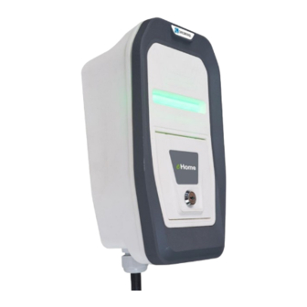
Page 17: Front Product View
Wallbox eHOME-Plus INSTRUCTION & INSTALLATION MANUAL 7 FRONT PRODUCT VIEW 1. Circontrol Logo 2. Front cover 3. Status RGB LED bar 4. OEM Logo 5. Frame 6. Front door with key lock 7. Optional devices © CIRCONTROL www.circontrol.com... -
Page 18: Inside Product View
8.1 MODEL eHOME-PLUS RCD Type A 1. EV tethered cable 2. Output contactor 3. Main boards 4. Current limit selector 5. Rear cover 6. RGB LEDs 7. Input terminals 8. Heating element 9. Power line 10. RCD Type A © CIRCONTROL www.circontrol.com... -
Page 19: Model Ehome-Plus Rcd Typea + Meter
8.2 MODEL eHOME-PLUS RCD Type A + Meter 1. EV tethered cable 2. Output contactor 3. Main boards 4. Currrent limit selector 5. Rear cover 6. RGB LEDs 7. Input terminals 8. Heating Element 9. Power line 10. RCD Type A 11. Meter © CIRCONTROL www.circontrol.com... -
Page 20: Model Ehome-Plus Rcd Typeb
8.3 MODEL eHOME-PLUS RCD Type B 1. EV tethered cable 2. Output contactor 3. Main board 4. Current limit selector 5. Power cover 6. RGB LEDs 7. Input terminals 8. Heating element 9. Power line 10. RCD Type B © CIRCONTROL www.circontrol.com... -
Page 21: Installation
Wallbox eHOME-Plus INSTRUCTION & INSTALLATION MANUAL 9 INSTALLATION 9.1 SUPPLIED MATERIAL MATERIAL Wallbox eHOME-Plus charging point User manual Cable gland M25x1.5 Safety key © CIRCONTROL www.circontrol.com... -
Page 22: Opening The Unit
Wallbox eHOME-Plus INSTRUCTION & INSTALLATION MANUAL 9.2 OPENING THE UNIT STEP ACTION Remove the screw at the bottom of the box. © CIRCONTROL www.circontrol.com... - Page 23 Using a screw driver, put it into the indicated marks, at the bottom of the box, and starting removing the frame doing click at the bottom. CLICK! Beware of not breaking the plastic of the frame with the screw driver. © CIRCONTROL www.circontrol.com...
- Page 24 Grabbing the frame with the hand by the lower part, pull and take it off totally, from the bottom to the top. CLICK! CLICK! CLICK! CLICK! CLICK! CLICK! To make it easier help yourself with the screw driver while pulling the frame off. © CIRCONTROL www.circontrol.com...
- Page 25 Remove the six screws of the front part by using a screw driver and take out the front part of the enclosure. Be sure that the unit is not energised before going forward with the opening procedure. © CIRCONTROL www.circontrol.com...
- Page 26 INSTRUCTION & INSTALLATION MANUAL STEP ACTION When the front part of the enclosure is off, you can access to the inside components of the unit. Only the authorised and qualified staff can manipulate electrical electronic components of the unit. © CIRCONTROL www.circontrol.com...
-
Page 27: Power Supply Line Cable Insertion
In all cases it is required to install a cable gland to ensure properly installation and preserve the IP of the unit. Cable insertion opening on the rear of the housing (breakable) Cable insertion opening at the bottom of the housing © CIRCONTROL www.circontrol.com... -
Page 28: Using The Rear Cable Insertion Opening
Install always double membrane seals to ensure IP protection of the charging point. Be careful of not damaging any of the inside components when breaking out the rear cable insertion opening. © CIRCONTROL www.circontrol.com... -
Page 29: Using The Bottom Cable Insertion Opening
Do not make any other holes on the enclosure. Use only the named cable insertion opening to install the required electric pipes. Install always either cable glands or double membrane seals to ensure IP protection of the charging point. © CIRCONTROL www.circontrol.com... -
Page 30: Wall Fixation Procedure
Below, it is shown the list of materials (not included) that are necessary to fix the unit on the wall: MATERIAL PICTURE DIMENSIONS Wall plug Ø 6mm Screws 3x45mm All materials shown in the above table may vary depending on the wall surface type. © CIRCONTROL www.circontrol.com... -
Page 31: Considerations
Please ensure that the installation surface is flat. 9.4.3 INSTALLATION STEP ACTION Adjust the vertical position of the charging point to ensure the correct vision and management for the end user. Minimum recommended height: 600 mm Please comply with your country specifications. © CIRCONTROL www.circontrol.com... - Page 32 4. Check whether the box has any inclination using a level tool. a) Use Ø 6 drill size to make the 3 holes into the wall. b) Install the anchor according to the surface material. © CIRCONTROL www.circontrol.com...
- Page 33 Do not make any other holes on the housing; otherwise the water can enter the unit when it rains. All screws and wall plugs needed to attach the unit to the wall are not included. © CIRCONTROL www.circontrol.com...
-
Page 34: Electrical Installation
For protecting the power line, it is necessary to install a Miniature Circuit Breaker (MCB) and a Residual Current Device (RCD) externally. The charging point is set to 16A / 32A, depending on the model, from factory default settings. © CIRCONTROL www.circontrol.com... -
Page 35: Power Supply Line Connection
Wallbox eHOME-Plus INSTRUCTION & INSTALLATION MANUAL 9.5.2 POWER SUPPLY LINE CONNECTION Perform the 230 VAC Single-phase connections as shown in the picture below. Do not forget to connect the ground cable (PE) to its corresponding terminal. © CIRCONTROL www.circontrol.com... -
Page 36: Current Limit Selector
The default setting of the unit is the maximum current which allows the unit power supply cable. Be sure that the position of the current limit selector is setup according to the output current of your unit. © CIRCONTROL www.circontrol.com... - Page 37 INSTRUCTION & INSTALLATION MANUAL On the following table is shown the different values available for this current limit selector: POSITION LIMIT CURRENT NOT USED 10 A 13 A 16 A 20 A 32 A NOT USED NOT USED NOT USED © CIRCONTROL www.circontrol.com...
-
Page 38: Remote Control Input
This remote control input is enabled by default, by means of a jumper (as shown in the picture below). You must remove the jumper to use the input 4-5. Be sure that the jumper is connected, otherwise the charging process cannot start. © CIRCONTROL www.circontrol.com... -
Page 39: Electrical Hazard
7. After the properly checked of the previous points, it is possible to make the reset in the RCD. On the left side, the view of the RCD type B used in the Wallbox eHOME-Plus. On the right side, the view of the RCD type A used in the Wallbox eHOME-Plus © CIRCONTROL www.circontrol.com... -
Page 40: Maintenance Of Residual-Current Device (Rcd)
Indication in the blue square of the Test button (T) in the RCD. 11.1.3 ENERGY METER The energy meter counts the total energy consumed incrementally from the point of commissioning. Therefore, it shows the value during the total lifetime of the meter. View of meter © CIRCONTROL www.circontrol.com... -
Page 41: Closing The Unit
INSTRUCTION & INSTALLATION MANUAL 11.2 CLOSING THE UNIT STEP ACTION Place back the 6 screws from the front cover in order to close the unit. Beware of the cables between the cover and the base while closing the unit. © CIRCONTROL www.circontrol.com... - Page 42 Put the frame back, from the top to the bottom of the box, ensuring it does click at the six points shown in the picture. CLICK! CLICK! CLICK! CLICK! CLICK! CLICK! Be sure that the frame is properly adjusted to the front cover in order to preserve the IP of the unit. © CIRCONTROL www.circontrol.com...
-
Page 43: Checking The Unit Status
LED bar operating colors: PLUG STATE LED BAR COLOR Available Green Charging Blue (flashing) Charged Blue Fault Red (flashing) Heating Orange NOTE: For further information about the different status led bar sequences, please refer to OPERATING INSTRUCTIONS section. © CIRCONTROL www.circontrol.com... -
Page 44: Home Beon (Optional)
EV, when there is enough current, the system is re-establishing the charging process automatically For installation, connections and further information of HOME BeON, please refer to the instruction manual of the product HOME BeON. © CIRCONTROL www.circontrol.com... -
Page 45: Technical Data
Operating humidity To 95% RH Non-condensing Net weight OPTIONAL FEATURES RCD A 30mA 40A earth-leakage protection type A RCD B 30mA 40A earth-leakage protection type B Energy meter Class B Active Energy / Class 2 Reactive Energy © CIRCONTROL www.circontrol.com... -
Page 46: Notes
Wallbox eHOME-Plus INSTRUCTION & INSTALLATION MANUAL 15 NOTES © CIRCONTROL www.circontrol.com... - Page 47 Wallbox eHOME-Plus INSTRUCTION & INSTALLATION MANUAL © CIRCONTROL www.circontrol.com...
- Page 48 www.circontrol.com...
Need help?
Do you have a question about the eHOME-PLUS Series and is the answer not in the manual?
Questions and answers