Circontrol WALLBOX SMART Series Installation Manual
Hide thumbs
Also See for WALLBOX SMART Series:
- Installation manual (28 pages) ,
- Installation manual (32 pages)
Table of Contents
Advertisement
Quick Links
Advertisement
Table of Contents

Related Manuals for Circontrol WALLBOX SMART Series


Summary of Contents for Circontrol WALLBOX SMART Series
- Page 1 INSTALLATION MANUAL MODEL: CCL-WBM-SMART-MID-16A WALLBOX SMART SERIES...
- Page 2 INSTALLATION MANUAL Wallbox Smart Series – Installation manual This document is copyrighted, 2016 by Circontrol, S.A. All rights are reserved. Circontrol, S.A. reserves the right to make improvements to the products described in this manual at any time without notice.
-
Page 3: Table Of Contents
WIRING ..........................20 SIM CARD (FOR 3G MODELS) ..................... 21 ETHERNET CONNECTION ......................22 CLOSING THE UNIT ........................23 UNIT VERIFICATION ........................24 ADDITIONAL SETTINGS ........................ 25 CHANGE MAX. CURRENT OF PLUG .................... 25 TECHNICAL DATA ......................... 26 © CIRCONTROL www.circontrol.com... -
Page 4: Preface
Complies with IEC 61851, Electric vehicle conductive charging system (IEC 61851-1 and IEC 61851-22) Complies with IEC 62196, Plugs, socket-outlets, vehicle couplers and vehicle inlets (IEC 62196-1 and IEC 62196-2). Directives 2004/108/EC, EMC; 2006795/EC, Low voltage Directive RFID complies with ISO 14443A/B © CIRCONTROL www.circontrol.com... -
Page 5: Installation Guidelines
Do not use this unit for anything other than electric vehicle charging modes are expected in IEC 61851. Do not modify this unit. If modified, CIRCONTROL will reject all responsibility and the warranty will be void. Comply strictly with electrical safety regulations according to your country. -
Page 6: Electrical Wiring Considerations
ADDITIONAL SETTINGS section in order to know how to change this value. Please refer to the TECHNICAL DATA section to consult the default factory settings from maximum output current of the charge point. Depending of the model this value may vary. © CIRCONTROL www.circontrol.com... -
Page 7: Space Requirements
CCL-WBM-SMART-MID-16A INSTALLATION MANUAL SPACE REQUIREMENTS When installing the equipment respect minimum distances space for maintenance and safety reasons. Minimum height y recommended is: 1,2m. Please comply accordingly to your country specifications. Units specified in mm © CIRCONTROL www.circontrol.com... -
Page 8: Product Dimensions
CCL-WBM-SMART-MID-16A INSTALLATION MANUAL 3 PRODUCT DIMENSIONS Units specified in mm © CIRCONTROL www.circontrol.com... -
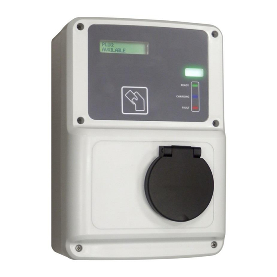
Page 9: Product Overview
CCL-WBM-SMART-MID-16A INSTALLATION MANUAL 4 PRODUCT OVERVIEW 1. Liquid Cristal Display 2. RFID Reader 3. Plug status beacon 5. Plug – Type 2 4. Front cover © CIRCONTROL www.circontrol.com... -
Page 10: Component Parts Location
3. Plug – MID Meter 1. CCL1-Mini Device 2. Cellular modem 5. Plug – LED beacon 4. 12V Power Supply 6. Type 2 locking system 7. Plug – Mode 3 8. Plug – Contactor 9. AC terminals © CIRCONTROL www.circontrol.com... -
Page 11: Installation
CCL-WBM-SMART-MID-16A INSTALLATION MANUAL 6 INSTALLATION SUPPLIED MATERIAL MATERIAL Charge point Installation manual Cable gland M25x1.5 CirCarLife RFID Mifare card © CIRCONTROL www.circontrol.com... -
Page 12: Opening The Unit
INSTALLATION MANUAL OPENING THE UNIT STEP ACTION Remove 6 screws from the front cover in order to open the unit: Beware of the cables between cover and base when wall mounted unit is opened during the installation tasks. © CIRCONTROL www.circontrol.com... -
Page 13: Cable Insertion
In all cases it is required to install a cable gland to ensure properly installation. Cable insertion from above Cable insertion from behind Cable insertion from below Protect the contactor and all possible electronic devices inside the unit before breaking the cable insertions. © CIRCONTROL www.circontrol.com... -
Page 14: Cable Insertion From Above / Below
TOP / BOTTOM VIEW Do not make new holes in others parts of the enclosure. Use only the cable insertion openings to install the required electric pipes. Install always cable glands to ensure IP protection of the charge point. © CIRCONTROL www.circontrol.com... -
Page 15: Cable Insertion From Behind
Do not make new holes in others parts of the enclosure. Use only the cable insertion openings to install the required electric pipes. Install always cable glands or a double membrane seals to ensure IP protection of the charge point. © CIRCONTROL www.circontrol.com... -
Page 16: Recommendations
Ethernet communications cable (if necessary) should be introduced at the top of the unit and power supply wires below the unit. Power wires and communications wires must be installed using different electrical pipes to ensure properly function of the charge point. © CIRCONTROL www.circontrol.com... -
Page 17: Fixation Procedure
Water drainage from the top side to the rear side of the unit must be ensured. Charge point must be installed vertically. Use a flat surface. Use a level tool to ensure installation at an angle of 90º. © CIRCONTROL www.circontrol.com... -
Page 18: Installation
2. Place it on a flat surface. 3. Use 4x45mm screws to attach the unit to the wall. 4. Check charge point has REAR VIEW no inclination using a level tool. Units specified in mm © CIRCONTROL www.circontrol.com... - Page 19 Do not make new holes in other parts of the plastic from the unit; otherwise water can enter into the unit when it rains. All screws and wall plugs needed to attach the unit to the wall are not included. © CIRCONTROL www.circontrol.com...
-
Page 20: Electrical Installation
32A. Please refer to ADDITIONAL SETTINGS about how to increase the maximum current output from the configuration. Power supply wires should be introduced below of the unit. Please refer to ELECTRICAL WIRING CONSIDERATIONS before proceeding to the wiring installation. © CIRCONTROL www.circontrol.com... -
Page 21: Wiring
CCL-WBM-SMART-MID-16A INSTALLATION MANUAL 6.5.2 WIRING SINGLE-PHASE WIRING Perform the 230V AC Single-phase connection as shown. Do not forget to connect the ground cable (PE) to the supply terminal. © CIRCONTROL www.circontrol.com... -
Page 22: Sim Card (For 3G Models)
SIM card holder is located at the left side cellular modem. The SIM card and its contacts can be easily damaged by scratches or bending, so be careful when handling, inserting or removing the card. Insert the SIM card with the contact surface facing down. © CIRCONTROL www.circontrol.com... -
Page 23: Ethernet Connection
CCL1-Mini Module This unit is shipped from the factory with default network setting of “DHCP enabled”. It means that the charge station will try to obtain an IP address automatically from the network (if it is available). © CIRCONTROL www.circontrol.com... -
Page 24: Closing The Unit
CCL-WBM-SMART-MID-16A INSTALLATION MANUAL CLOSING THE UNIT STEP ACTION Place back 6 screws from the front cover in order to close the unit: Beware of the cables between cover and base while closing the unit. © CIRCONTROL www.circontrol.com... -
Page 25: Unit Verification
2. Check each plug is in proper conditions before start operation. 3. Check no abnormal noise appears while unit is charging. 4. Check all beacons indicators are lighting. Below table shows possible LED beacon colors: PLUG STATE BEACON COLOR Available Green Charging Blue Fault © CIRCONTROL www.circontrol.com... -
Page 26: Additional Settings
3- Select the desired plugs to set a new current value. By default, all plugs are selected. 4- Set the new current value to apply on each plug. 5- Click under Apply settings button and wait until the process ends. © CIRCONTROL www.circontrol.com... -
Page 27: Technical Data
Operating humidity To 95% RH Non-condensing RFID system ISO / IEC14443A / B Display LCD Backlight double line text Power limit control Mode 3 PWM control according ISO / IEC 61851-1 Interface protocol OCPP / XML Net weight © CIRCONTROL www.circontrol.com... - Page 28 www.circontrol.com...
Need help?
Do you have a question about the WALLBOX SMART Series and is the answer not in the manual?
Questions and answers