Table of Contents
Advertisement
Quick Links
Advertisement
Table of Contents

Related Manuals for Circontrol eHome 5


Summary of Contents for Circontrol eHome 5
- Page 1 Installation Manual eHome 5...
-
Page 2: Revision Log
Revision log Date Version Description 11/2024 M457B10-03-24A Initial release... - Page 3 C O P Y R I G H T I N F O R M A T I O N This document is copyrighted, 2024 by Circontrol, S.A. All rights are reserved. Circontrol, S.A. reserves the right to make improvements to the products described in this manual at any time without notice.
-
Page 4: Table Of Contents
Here’s the guide to install and configure your eHome 5 1 — So, hello! 2 — Before installation A - Important safety instructions B - Electrical wiring considerations 3 — Overview 4 — Dimensions 5 — Installation A - Minimum distances... - Page 5 6 — Installation wizard A - Language B - Power management C - Network D - Authorisation 7 — Setup Webpage A - Dashboard B - Configuration C - Maintenance 8 — Verification A - Beacon colours B - Additional beacon colours 9 —...
-
Page 6: So, Hello
It is mandatory to follow the basic security information supplied in this manual to ensure safe and proper installation. Failure to follow safety instructions may involve personal injury, equipment damage and danger of death. CIRCONTROL is not responsible for events arising from such breach. THE FOLLOWING SYMBOLS ARE USED FOR IMPORTANT... - Page 7 Info I N F O R M A T I O N It provides useful information to be taken into account. Standards: • Complies with IEC 61851, Electric vehicle conductive charging system (IEC 61851-1:2017 and IEC 61851-21-2:2018). • Complies with IEC 62196, Plugs, socket-outlets, vehicle couplers and vehicle inlets (IEC 62196-1 and IEC 62196-2).
-
Page 8: Before Installation
Use only Circontrol supplied spare parts. • Do not use this unit if the enclosure or the EV connector is broken, cracked, open, or shows any other indication of damage. CIRCONTROL — eHome 5 — Installation Manual... -
Page 9: B) Electrical Wiring Considerations
Electrical wiring considerations Warnings Take into consideration this section before start wiring connections of the Charge Point. 1 - E L E C T R I C A L P R O T E C T I O N S Charge point may not include elements of electrical protection. -
Page 10: Overview
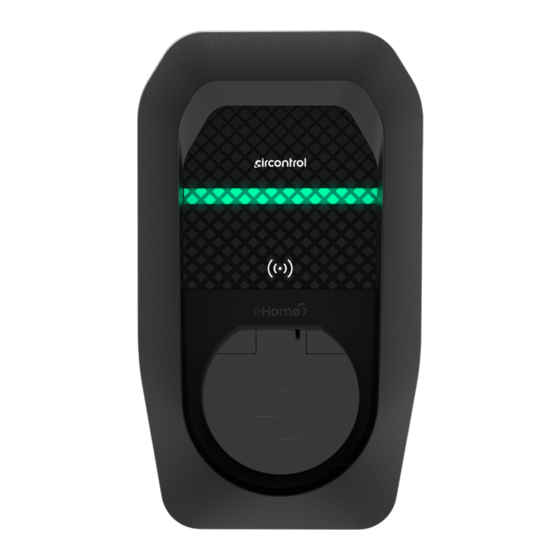
S H O R T D E S C R I P T I O N eHome 5 is specially designed to be easily installed both in outdoor and indoor private car parks, and to be compatible with all the EV models of the market according to European standard IEC 61851-1, by just plugging your car. - Page 11 1 — Circontrol logo 4 — Cable 7 — RFID reader 2 — RGB LED bar 5 — Frame 3 — Front cover 6 — Socket...
-
Page 12: Dimensions
Dimensions 180 mm 115 mm 315 mm 158 mm 79 mm 79 mm 238 mm CIRCONTROL — eHome 5 — Installation Manual... - Page 13 100 mm 71 mm Ø5 mm 70 mm 100 mm 150 mm 25 mm...
-
Page 14: Installation
The installation kit has been tested on a concrete wall. Before the installation, a qualified installer must check that the wall is in a perfect condition, and which screws and anchors are suitable for that conditions. CIRCONTROL — eHome 5 — Installation Manual... -
Page 15: Minimum Distances
Minimum distances When installing the unit, some space shall be reserved for usability, maintenance and safety reasons. Please comply accordingly to your country specifications. The next picture shows the minimum distances: Front view Info In case of having the cable version, cable holder must be installed between 700 mm and 1200 mm in height. -
Page 16: B) Opening
Opening Take out the front part of the enclosure. Warnings Be sure that the unit is not energized before going forward with the opening procedure. CIRCONTROL — eHome 5 — Installation Manual... -
Page 17: C) Power Supply Line And Data Connection
Power supply line and data connection There are two possibilities to insert the electric wires: a) Breaking out the cable insertion opening on the rear of the housing. b) Using the right cable insertion opening at the bottom of the housing. In both cases it is required to install a cable gland (included) to ensure properly installation and preserve the IP degree of the unit. - Page 18 Do not make any other holes on the enclosure. Use only the named cable insertion opening to install the required electric pipes. Install always either cable glands or double membrane seals to preserve the IP degree of the Charge Point. CIRCONTROL — eHome 5 — Installation Manual...
-
Page 19: D) Positioning
Positioning Make holes for fastener screws. 158 mm 238 mm 79 mm 700 mm ≤ X ≤ 1000 mm Front view Place the provided template on a flat surface. Check whether it has any inclination using a level tool. Mark 3 holes using the installation template. Use a Ø... - Page 20 Check whether it has any inclination using a level tool. Mark 3 holes using the cable holder itself. Use a Ø 6 drill size to make the 3 holes into the wall. Install the anchors according to the surface material. CIRCONTROL — eHome 5 — Installation Manual...
-
Page 21: E) Fixing
Fixing 1. Use a screwdriver to fix the Charge Point (and cable holder if it is the case) on the wall (recommended screw dimensions: 4x45mm). 2. Use only the Charge Point holes indicated in the above picture to fix the Charge Point on the wall. -
Page 22: G) Power Supply Line Connection
Terminal block maximum cross-section: 10 mm Do not forget to connect the ground cable to the ground terminal Minimum cable handling temperature: -15ºC Permissible conductor operating temperature: > +90ºC 18 mm tips must be used. CIRCONTROL — eHome 5 — Installation Manual... -
Page 23: Current Transformer
Current transformer Current transformer is a device used to optimise the charge. Analysing the total current consumption in residential facilities, it manages the remaining current for the Charge Point, avoiding any tripping on the Main Circuit. Note that this device is only available in Single-Phase Charge Points. The device is placed downstream of the main power switch and upstream of the main loads and is connected to the J602 terminal of the lowest PCB. -
Page 24: I) Optional External Meter
BOR1 terminal of the upper PCB as shown in the following diagram: MODBUS RS485 BOR1 Note: It is recommended to use 2 x 0.22 mm YCY cables. Info For more information about its configuration, please refer to sections 6b and 7b - Power Management. CIRCONTROL — eHome 5 — Installation Manual... -
Page 25: J) Closing
Closing Screw the 6 bolts from the front cover in order to close the Charge Point. Screws are securely tightened at 1 Nm. Warnings Be aware of the cables between the cover and the base while closing the Charge Point. Put the frame, from the top to the bottom of the box, ensuring it does click and screw the bold on the bottom. -
Page 26: Installation Wizard
Within the wizard, there is an initial configuration of the charger, which consists of four different tabs to go through. In addition to the URL, it can also be accessed via the following IP: 192.168.137.1 CIRCONTROL — eHome 5 — Installation Manual... -
Page 27: A) Language
Language This section basically consists of selecting a language from those available for the rest of the process. Power management In this section, the following settings can be modified: Charger limit: adjust the maximum current of the charger according to the maximum power supported by the power supply. Dynamic balance: enables power management with the current transformer or external meter and solar integration option. - Page 28 In this case, the external meter as a measuring device will be automatically selected (and will be the only option available). In addition, the option to allow net hourly balancing will be enabled. CIRCONTROL — eHome 5 — Installation Manual...
-
Page 29: C) Network
Network This section consists of selecting the connectivity of the charger Wi-Fi Enter the Wi-Fi SSID and Password manually or by pressing the ‘Scan’ button. Then, check the connection by pressing the ‘Connect’ button. A successful connection should look like the following image, showing the IP assigned automatically: Please remember to check the connection with the ‘Connect’... -
Page 30: D) Authorisation
The identification mode can also be chosen: • Open: no identification required. • Restricted: only RFID cards that are registered in the websetup or APP can be used. CIRCONTROL — eHome 5 — Installation Manual... - Page 31 THIS PAGE HAS BEEN INTENTIONALLY LEFT BLANK...
-
Page 32: Setup Webpage
In the main page, ‘EN’ button, or the acronym of the previously selected language button, allows to switch back to another language. To the right of the language button, there is another button that allows to close the current session. CIRCONTROL — eHome 5 — Installation Manual... -
Page 33: A) Dashboard
Dashboard Charge Point Status This tab shows the current status of the charger and its firmware version. In addition, relevant information about the socket is displayed: • Status • Available current • Energy from the current charge transaction System Information This tab shows the different naming tags that the eHome has (device UID and Hostname), time (uptime and local time) and event logs and possible alarms. - Page 34 The information displayed in this tab is basically related to the status of the OCPP and its configuration. Network The information displayed in this tab is basically related to the status of the network/s (Ethernet and/or Wi-Fi) with its configured parameters and DNS. CIRCONTROL — eHome 5 — Installation Manual...
-
Page 35: B) Configuration
Configuration Power Management This section is the same as the corresponding one of the installation wizard. It shows the configuration related to the power management previously done. It also allows for remote power management through an OCPP connection to an OCPP Central System with Smart Charging. - Page 36 There is also the option to disable the current limit by pressing the ‘No charge’ button. To be able to use the scheduler with the APP, the option here must be enabled. Please remember to save your changes before switching at another option. CIRCONTROL — eHome 5 — Installation Manual...
- Page 37 If solar integration has been configured, when adding new time slots, a solar panel symbol will appear instead of the ‘No charge’ button. If this button is pressed, only the solar surplus will be used, meaning that there will be no current limit (0 A). OCPP This section allows to link the eHome to the Central System, give it a name and assign a password.
- Page 38 Channel: Channel of the eHome network. • Encryption: Level of encryption. • Password: Password of the eHome network. • ‘Hidden’ checkbox: Hide the eHome network. The name of the Access Point can be modified in the mDNS tab. CIRCONTROL — eHome 5 — Installation Manual...
- Page 39 In case of selecting ‘Station, the following parameters can be configured: • SSID: Name of the network. • Channel: Channel of the network. • Encryption: Level of encryption. • Password: Password of the network. • Protocol: DHCP or Static. In case of Static, the IP address must be assigned manually, along the netmask and gateway.
- Page 40 Please remember to save your changes before switching at another option. In the DNS tab, both Primary and Secondary DNS can be configured. CIRCONTROL — eHome 5 — Installation Manual...
- Page 41 mDNS In the mDNS tab, the hostname and description of the Access Point can be modified. Security This section provides information refering to the credentials required to enter the websetup. A new password can be set.
- Page 42 In ‘Open’ mode, no authorisation is required to initiate a charge transaction. In order to record them, OCPP must be disabled. Otherwise, the eHome 5 APP must be used to add new RFID cards. CIRCONTROL — eHome 5 — Installation Manual...
- Page 43 Time In this section, the timezone in which the charger is installed can be selected. In addition, the local time can be linked to a server by enabling the ‘NTP’ option. In case of selecting the ‘Manual’ option, the charger can be synchronised with the device being used (smartphone or PC).
-
Page 44: Maintenance
It also includes some relevant information about the firmware version of some devices. To obtain the latest firmware version file please contact CIRCONTROL Support Department. More information in ‘Need help?’ chapter. CIRCONTROL — eHome 5 — Installation Manual... - Page 45 System Status This section provides relevant information about the status of some components of the eHome such as the Mode 3 PCB and additional parameters. Advanced This section allows to reset the eHome in two different ways: • Factory Reset: Restoring of all settings to their factory defaults. •...
-
Page 46: Verification
7 — P R E V E N T I V E M A I N T E N A N C E Check the installation annually by a qualified technician. Info Please refer to the User Manual to see possible eHome errors. CIRCONTROL — eHome 5 — Installation Manual... -
Page 47: A) Beacon Colours
Beacon colours The states that occur in a typical charging process and their associated colours and behaviour are listed in the following table: Charge Beacon Color Design Point state colour behaviour Available Green Fixed RFID authorised Green Blink RFID not Blink authorised Action... -
Page 48: B) Additional Beacon Colours
State where OCPP is enabled and neither Wi-Fi nor Ethernet is connected (central blink every 20 seconds). Or OCPP is enabled and Wi-Fi or Ethernet is connected, but OCPP is not connected to the Central System (central blink every 30 seconds). CIRCONTROL — eHome 5 — Installation Manual... - Page 49 THIS PAGE HAS BEEN INTENTIONALLY LEFT BLANK...
-
Page 50: Technical Data
5 T Connector Type 2 Net weight 3 kg 4 kg Enclosure ABS-PCV0 Dimensions (W x H x D) 180 x 315 x 115 mm Derating can be applied above this temperature. CIRCONTROL — eHome 5 — Installation Manual... - Page 51 RCD shall comply with one of the following standards: IEC 61008-1, IEC 61009-1, IEC 60947-2 or IEC 62423. Only available in single-phase models. Optional devices eHome 5 Socket eHome 5 Cable Type 1 Type 2 Tethered cable (5 m length)
-
Page 52: Need Help
Need help? CIRCONTROL — eHome 5 — Installation Manual... - Page 53 In case of any query or if further information is required, please contact our Support Department. support@circontrol.com www.circontrol.com (+34) 937 362 940 Circontrol Expert Area...
- Page 54 CIRCONTROL eHOME 5 INSTALLATION MANUAL A comprehensive guide on how to install and verify your charge point. Scan me to download the User Manual: CIRCONTROL S.A. - ALL RIGHTS RESERVED...
Need help?
Do you have a question about the eHome 5 and is the answer not in the manual?
Questions and answers