
Related Manuals for Ruijie Networks Reyee RG-NBS3100-8GT2SFP-P-V2


Summary of Contents for Ruijie Networks Reyee RG-NBS3100-8GT2SFP-P-V2
- Page 1 Ruijie Reyee RG-NBS3100-8GT2SFP-P-V2 Switch Installation Guide Document Version: V1.1 Date: May 14, 2024 Copyright © 2024 Ruijie Networks...
- Page 2 The names, links, descriptions, screenshots, and any other information regarding third-party software mentioned in this document are provided for your reference only. Ruijie Networks does not explicitly or implicitly endorse or recommend the use of any third-party software and does not make any assurances or guarantees concerning the applicability, security, or legality of such software.
-
Page 3: Preface
Preface Intended Audience This document is intended for: Network engineers Technical support and servicing engineers Network administrators Technical Support The official website of Ruijie Reyee: https://reyee.ruijie.com Technical Support Website: https://reyee.ruijie.com/en-global/support Case Portal: https://www.ruijienetworks.com/support/caseportal Community: https://community.ruijienetworks.com ... - Page 4 This manual provides the device installation steps, hardware troubleshooting, module technical specifications, and specifications and usage guidelines for cables and connectors. It is intended for the users who have some experience in installing and maintaining network hardware. At the same time, it is assumed that the users are already familiar with the related terms and concepts.
-
Page 5: Table Of Contents
Contents Preface ..............................I 1 Product Introduction .......................... 1 1.1 Overview ............................ 1 1.2 Package Contents........................1 1.3 Appearance ..........................2 1.3.1 Front Panel ........................2 1.3.2 Rear Panel ........................4 1.4 Technical Specifications ......................4 2 Preparing for Installation ........................6 2.1 Safety Precautions ........................ - Page 6 2.2.8 Surge Protection Requirements................... 10 2.2.9 Installation Site Requirements ..................11 2.3 Rack Requirements ......................... 11 2.4 Tools ............................12 3 Installing the Switch ........................13 3.1 Installation Flowchart ....................... 13 3.2 Preparing for Installation ......................14 3.3 Installing the Switch ......................... 14 3.3.1 Precautions ........................
- Page 7 4.2 Powering On ..........................19 4.2.1 Checklist Before Power-on ..................19 4.2.2 Checklist After Power-on ..................... 19 5 Common Troubleshooting ....................... 20 5.1 Troubleshooting Flowchart ...................... 20 5.2 Common Faults ........................20 6 Appendixes ............................22 6.1 Connectors and Media ......................22 6.2 Mini-GBIC and SFP Modules....................
-
Page 8: Product Introduction
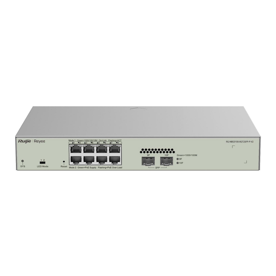
Installation Guide Product Introduction Product Introduction Overview 10/100/1000Base-T Ethernet 1000Base-X Console Power Model Port with Auto-Negotiation SFP Port Port Supply 1 x fixed RG-NBS3100- power supply 8GT2SFP-P-V2 module Note The eight Ethernet ports are PoE-capable, and comply with the IEEE 802.3af and 802.3at standards. These ports support the Alternative A PoE power supply mode, which deliver power through pins 1/2 (+) and pins 3/6 (-). -
Page 9: Appearance
Installation Guide Product Introduction Note The package contents are subject to the purchase contract, and actual delivery may vary. Please check the items carefully against the package contents or purchase contract. If you have any questions or notice any errors, please contact your distributor. - Page 10 Installation Guide Product Introduction Table 1-2 Front Panel Components Component Description Off: The switch is not powered on. Slow blinking green (flash every two seconds): The switch is operating properly, but has insufficient power for PoE, or is not connected to Ruijie Cloud.
-
Page 11: Rear Panel
Installation Guide Product Introduction 1.3.2 Rear Panel Figure 1-2 Rear Panel Table 1-3 Rear Panel Components Component Description Power Cord Secures the power cord. Retention Clip Power Connects to an external AC power supply. Connector Grounding stud Secures the grounding lug to connect the chassis to earth ground. Technical Specifications Table 1-4 Technical Specifications... - Page 12 Installation Guide Product Introduction 15 W (no PoE load) Operating 0º C to 50º C (32º F to 122º F) Temperature Storage –40º C to 70º C (–40º F to 158º F) Temperature Operating Humidity 10% to 90% RH (non-condensing) Storage Humidity 5% to 95% RH (non-condensing) Number of Fans...
-
Page 13: Preparing For Installation
Installation Guide Preparing for Installation Preparing for Installation Safety Precautions Note To avoid bodily injury and device damage, please carefully read the safety precautions before you install the device. The following safety precautions may not cover all possible dangers. 2.1.1 General Safety Precautions ... -
Page 14: Esd Safety
Installation Guide Preparing for Installation Select the right leakage protector (also called “leakage current switch” or “leakage current breaker”) for the power supply system. This device automatically disconnects the power supply in the event of leakage and the risk of electric shock. A leakage protector should meet the following requirements: ○... -
Page 15: Installation Environment Requirements
Installation Guide Preparing for Installation Figure 2-1 Laser Product Warning Warning Do not approach or look into any optical port under any circumstances. This may cause permanent damage to your eyes. Installation Environment Requirements To ensure the normal operation and prolonged service life of the device, it is essential to install it indoors in a location that meets the following requirements. -
Page 16: Cleanliness Requirements
Installation Guide Preparing for Installation Note The ambient temperature and humidity of the device are measured 1.5 m (59.06 in.) above the floor and 0.4 m (15.75 in.) before the switch rack when there is no protective plate in front or at the back of the rack. 2.2.5 Cleanliness Requirements Dust poses a major threat to the running of the device. -
Page 17: Anti-Interference Requirements
Installation Guide Preparing for Installation conditions at the installation site according to the grounding specifications, and complete grounding properly based on the actual situation. Safety Grounding Ensure that the cabinet and power distribution device are securely grounded if the device uses the AC power supply. -
Page 18: Installation Site Requirements
Installation Guide Preparing for Installation 2.2.9 Installation Site Requirements Regardless of whether the device is installed in a rack or on a workbench, the following conditions must be met: Maintain a proper clearance around air vents for heat dissipation. ... -
Page 19: Tools
Installation Guide Preparing for Installation Tools Table 2-3 Tools Phillips screwdriver, power cords, Ethernet cables, cage nuts, diagonal plier, and cable Common Tools ties Special Tools Anti-ESD glove, wire stripper, common crimping plier, RJ45 crimping plier, and wire cutter Meters Multimeter Relevant PC, display, and keyboard... -
Page 20: Installing The Switch
Installation Guide Installing the Switch Installing the Switch Caution Before installing the device, make sure that you have carefully read the requirements described in Chapter 2. Installation Flowchart Figure 3-1 Installation Flowchart Install the switch Ground the switch Connect the power supply Connect the cables Bundle the cables Verify the installation... -
Page 21: Preparing For Installation
Installation Guide Installing the Switch Preparing for Installation The installation site provides sufficient space for heat dissipation. The installation site meets the temperature and humidity requirements of the device. The power supply is available in the installation site and meets current requirements. ... - Page 22 Installation Guide Installing the Switch Figure 3-2 Securing Mounting Brackets Follow the steps below to mount the switch in a 19-inch rack: (1) Verify that the mounting brackets are securely attached to both sides of the switch (2) Install the cage nuts into the square holes of the rack posts. (3) Have one person support the bottom of the switch while moving it along the rack to find the desired position.
-
Page 23: Installing The Switch On A Workbench
Installation Guide Installing the Switch 3.3.3 Installing the Switch on a Workbench When a standard rack is unavailable, a common approach is to place the switch on a clean workbench. The installation steps are as follows: (1) As show in Figure 3-4, attach the four rubber feet to the four corners at the bottom of the switch. -
Page 24: Connecting The Switch To Earth Ground
Installation Guide Installing the Switch Connecting the Switch to Earth Ground The switch has a grounding stud on the rear panel. Connect the grounding stud to the grounding lug of the rack and then connect the grounding lug of the rack to the ground buss bar of the machine room. 3.4.1 Precautions ... -
Page 25: Bundling Cables
Installation Guide Installing the Switch (4) Insert the twisted pair cable with RJ45 connector into the corresponding ports according to the panel identification, and distinguish the crossover cable and the straight-through cable. Bundling Cables 3.6.1 Precautions Bundle the power cords and other cables in a visually pleasing way. ... -
Page 26: Verifying Operating Status
Installation Guide Verifying Operating Status Verifying Operating Status Setting Up the Configuration Environment 4.1.1 Connect to network cables Plug one RJ45 connector of the Ethernet cable into the Ethernet port of the PC. Connect the other RJ45 connect to any port of the switch. 4.1.2 Log In to the Web Interface for Setup (1) Configure your PC with an IP address in the network of 10.44.77.XXX (Range: 1-255, excluding 200). -
Page 27: Common Troubleshooting
The device is not working properly Check the device installation Check the power connection Check the LEDs on the device Check the cable connection Contact Technical Support of Ruijie Networks Common Faults Symptom Possible Cause Suggested Action The login password... - Page 28 Installation Guide Common Troubleshooting occurs. The port is specially configured and mode as the interconnected switch. does not use the same work mode as the interconnected switch. The receiving and transmitting ends Exchange the transmission and receiving are connected incorrectly. ends of the optical fiber.
-
Page 29: Appendixes
Installation Guide Appendixes Appendixes Connectors and Media 1000BASE-T/100BASE-TX/10BASE-T Port The 1000BASE-T/100BASE-TX/10BASE-T is a 10/100/1000 Mbps auto-negotiation port that supports auto MDI/MDIX Crossover. Compliant with IEEE 802.3ab, 1000BASE-T requires Category 5e 100-ohm UTP or STP (recommended) with a maximum distance of 100 meters (328 feet). The 1000BASE-T port requires all four pairs of wires to be connected for data transmission. - Page 30 Installation Guide Appendixes The following figure shows wiring of straight-through and crossover cables for the 100BASE-TX/10BASE-T port. Figure 6-2 100BASE-TX/10BASE-T Twisted Pair Connections Optical Fiber Connection You can choose single mode or multimode fibers according to the module types. Figure 6-3 shows the connection of fiber-optic cable.
-
Page 31: Mini-Gbic And Sfp Modules
Installation Guide Mini-GBIC and SFP Modules We provide appropriate SFP modules (Mini-GBIC modules) according to the port types. You can select the module to suit your specific needs. Besides, the Mini-GBIC-GT modules are also supported. The following models and technical specifications of some SFP modules are listed for your reference. For details about the technical specifications, see Ruijie Hybrid Cable Installation and Reference Guide. - Page 32 Installation Guide SFP-SM1310 1310 -9.5 Table 6-3 1000Base-T SFP Copper Module Standard 1000Base-T SFP Module DDM (Yes/No) 1000Base-T Mini-GBIC-GT Table 6-4 SFP Module Cabling Specifications Connector Core Specifications Max. Cabling SFP Model Cable type (μm) Type Distance 62.5/125 275 m MINI-GBIC-SX-MM850 50/125 550 m...
- Page 33 Installation Guide RJ45 Mini-GBIC-GT Ethernet Cat 5 (or higher) twisted-pair cable 100 m cable Caution For optical modules with a cabling distance of over 40 km (24.85 miles) (including 40 km) (including 24.85 miles), install an optical attenuator to avoid overload on the optical receiver when using short- distance single-mode fibers (SMFs).
-
Page 34: Lightning Protection
Installation Guide Lightning Protection Installing an AC Power Arrester (Lightning Resistance Socket) When an AC power cord is introduced from outdoors and directly connected to the power port of the switch, the AC power port must be connected to an external lightning protection power strip to protect the switch against lightning strokes. - Page 35 Installation Guide rectify the polarity of the connection. If the indicator is still red, the arrester's PE terminal is not grounded. Installing the Ethernet Port Arrester Connect an Ethernet port arrester to the switch to prevent the damage by lightning before connecting an outdoor network cable to the switch.
- Page 36 Installation Guide The Ethernet port arrester is not delivered with the switch. Please purchase it based on actual requirements. The Ethernet port arrester user manual contains technical parameters and maintenance and installation instructions for the Ethernet port arrester. Carefully read this manual before installation. Pay attention to the following situations during the installation to avoid influencing the performance of the Ethernet port arrester: Reversed installation direction of the arrester.
-
Page 37: Cabling Recommendations
Cabling Recommendations When the switch is installed in a standard 19-inch rack, secure the cables around the cable management brackets. Adopt top cabling or bottom cabling according to the actual situation in the machine room. All cable connectors used for transit should be placed at the bottom of the cabinet rather than be exposed outside of the cabinet. - Page 38 Installation Guide Figure 6-6 Binding Cables Cables of different types (such as power cords, signal cables, and ground cables) should be separated in cabling and bundling. Mixed bundling is disallowed. When they are close to each other, you are advised to adopt crossover cabling.
- Page 39 Installation Guide When cables need to be bent, please bundle them up but do not tie them where the cables will be bent, as shown in Figure 6-8. Figure 6-8 Binding Cables Cables not to be assembled or remaining parts of cables should be folded and placed in a proper position of the rack or cable trough.
-
Page 40: Machine Room Site Selection
Installation Guide ①Flat washer ③Spring washer ②Nut ④Flat washer Hard power cords should be fastened in the terminal connection area to prevent stress on terminal connection and cable. Do not use self-tapping screws to fasten terminals. Power cords of the same type and in the same cabling direction should be bundled up into cable bunches, with cables in cable bunches clean and straight. - Page 41 Installation Guide Make sure the air vent of the machine room is away from the sewage pipe, septic tank, and sewage treatment tank. Keep the machine room under positive pressure to prevent corrosive gas from entering the machine room to corrode components and circuit boards. ...
Need help?
Do you have a question about the Reyee RG-NBS3100-8GT2SFP-P-V2 and is the answer not in the manual?
Questions and answers