Table of Contents
Advertisement
Quick Links
Advertisement
Table of Contents

Related Manuals for Ruijie Networks RG-S2628G-E


Summary of Contents for Ruijie Networks RG-S2628G-E
- Page 1 RG-S2600E Series Switch Hardware Installation and Reference Guide V1.31...
-
Page 2: Copyright Statement
This document is provided “as is”. The contents of this document are subject to change without any notice. Please obtain the latest information through the Ruijie Networks website. Ruijie Networks endeavors to ensure content accuracy and will not shoulder any responsibility for losses and damages caused due to content omissions, inaccuracies or errors. -
Page 3: Obtaining Technical Assistance
It is intended for the users who have some experience in installing and maintaining network hardware. At the same time, it is assumed that the users are already familiar with the related terms and concepts. Obtaining Technical Assistance Ruijie Networks website: http://www.ruijienetworks.com/ http://webchat.ruijie.com.cn Online customer services: ... -
Page 4: Product Overview
FE-SFP-LH15-SM1310 Mini-GBIC-SX Mini-GBIC-SX Mini-GBIC-LX Mini-GBIC-LH40 Mini-GBIC-ZX50 Mini-GBIC-ZX80 Mini-GBIC-ZX100 Mini-GBIC-GT The supported module type may change at any time. For the detailed change information, consult Ruijie Networks. M3000E-02SFP/GT Extension Module M3000E-STACK SFP Port 100Base-X 1000Base-X RPS Type Not supported Power Supply AC input: Rated voltage range: 100–240 VAC... -
Page 5: Product Appearance
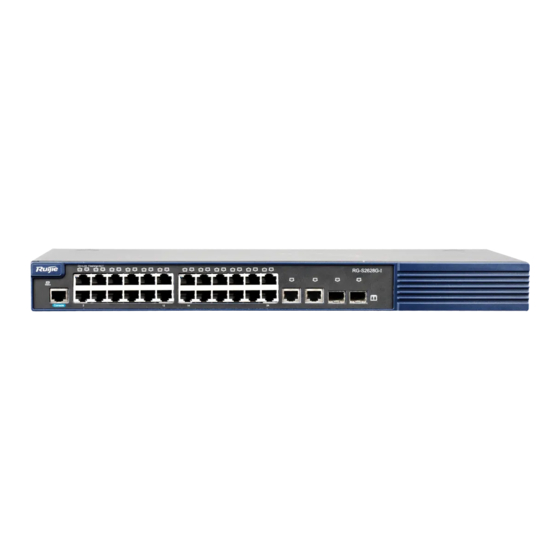
Without extension modules: 3.9 kg Product Appearance The front panel of the RG-S2628G-E switch provides twenty-four 10/100Base-T Ethernet ports, two gigabit SFP fiber optic/copper combo ports and one console port. The back panel provides AC power input ports and one extension module slot. -
Page 6: Back Panel
5. Console port 11. 100/1000Base-X SFP port indicator 6. 10/100Base-T adaptive Ethernet port Back Panel Figure 1-3 Back Panel of the RG-S2628G-E Switch 1. Grounding pole 3. Cable plug retention clip Note: 2. 3-core AC power interface 4. Extension module slot Power Supply System RG--S2628G-E powered either with AC power or DC power. -
Page 7: Led Indicators
The RG-S2628G-E is designed with no fans. To ensure good dissipation, sufficient ventilation space (10 cm distance from both sides and the back panel of the device) should be reserved to avoid blocking the air intake of the device; otherwise, the dissipation might be affected. -
Page 8: Specifications
FE-SFP-LH15-SM1310 Mini-GBIC-SX Mini-GBIC-SX Mini-GBIC-LX Mini-GBIC-LH40 Mini-GBIC-ZX50 Mini-GBIC-ZX80 Mini-GBIC-ZX100 Mini-GBIC-GT The supported module type may change at any time. For the detailed change information, consult Ruijie Networks. M3000E-02SFP/GT Extension Module Type M3000E-STACK SFP Port 100Base-X 1000Base-X RPS Type Not supported ... - Page 9 Temperature Support Warning EMC Standards GB9254-2008 Class A Safety Standards GB4943-2001 Dimensions 440 mm x 44 mm x 300 mm (W x H x D) With extension modules: 4.9 kg; Weight Without extension modules: 4.4 kg Product Appearance The front panel of the RG-S2652G-E switch provides forty-eight 10/100Base-T Ethernet ports, two gigabit SFP fiber optic/copper combo ports and one console port.
- Page 10 1. Grounding pole 2. 3-core AC power 4. Fan outlet Note: interface 5. Extension module slot 3. Cable plug retention clip Power Supply System RG-S2652G-E adopts the AC power input. AC input: Rated voltage range: 100–240 VAC Maximum voltage range: 90–264 VAC Frequency: 50–60 Hz Rated current: 2 A The power cable requirement: 10 A power cable...
- Page 11 Indicator Panel Status Meaning Identification Link indicator Status The switch is NOT receiving power. Blinking green Initialization is in progress. Continuous blinking indicates errors. Solid green The switch is operational. Solid yellow The switch gets a temperature warning. Check the operating environment of the switch. Solid red The switch is faulty.
- Page 12 Module Type FE-SFP-LX-MM1310 FE-SFP-LH15-SM1310 Mini-GBIC-SX Mini-GBIC-LX Mini-GBIC-LH40 Mini-GBIC-ZX50 Mini-GBIC-ZX80 Mini-GBIC-ZX100 Mini-GBIC-GT The supported module type may change at any time. For the detailed change information, consult Ruijie Networks. Extension Module M3000E-02SFP/GT SFP Port 100Base-X 1000Base-X RPS Type RG-RPS150 RG-RPS500 RG-RPS1100 ...
- Page 13 Storage temperature: -40ºC to 70ºC Working humidity: 10% to 90% RH Humidity Storage humidity: 5% to 90% RH Support adjustment of fan speed and warning of fan troubles. Temperature Warning Support EMC Standards GB9254-2008 Class A Safety Standards GB4943-2001 The RG-S2628G-P V1.0X: 440 mm x 44 mm x 400 mm Dimensions (W x H x D) The RG-S2628G-P V1.2X: 440 mm x 44 mm x 340 mm...
- Page 14 At present, the redundant power supply interface can be used together with the RPS150, RPS500, and RPS1100 that are manufactured by Ruijie Networks. Unless otherwise stated, other power supply modules cannot be used for power input; otherwise, an abnormality may occur on the switch or the switch may become damaged.
- Page 15 The RG-S2628G-P adopts turbine fans for heat dissipation purposes, thereby ensuring the device to function normally in the specified environment. Sufficient space (10 cm distance from both sides and the back panel of the cabinet) should be reserved to allow air circulation. Dust the device every three months to avoid blocking the ventilation openings. Figure 1-11 Flow Scheme of Heat Dissipation Powering Cabling for PD PoE designed for the RG-S2628G-P complies with 802.3af standard.
- Page 16 Indicator Panel Status Meaning Identification Solid red The switch is faulty. The module is not connected or installed. Extension module Module Solid green The module is operational. indicator The port is NOT connected. Extension module port Solid green The port is connected at 1000Mbps. indicator Blinking green The port is transmitting or receiving data at...
- Page 17 Mini-GBIC-ZX50 Mini-GBIC-ZX80 Mini-GBIC-ZX100 Mini-GBIC-GT The supported module type may change at any time. For the detailed change information, consult Ruijie Networks. Extension Module Not supported SFP Port Only 25F and 26F support 100Base-X, 25F, 26F, 27F and 28F support 1000Base-X.
- Page 18 Storage humidity: 5% to 90% RH Support adjustment of fan speed and warning of fan troubles. Temperature Warning Support EMC Standards GB9254-2008 Class A Safety Standards GB4943-2001 Dimensions 440 mm x 44 mm x 260 mm (W x H x D) Weight 4.5 kg Product Appearance...
- Page 19 Back Panel Figure 1-14 Back Panel of the RG-S2628G-P V2.XX Switch 3. 3-core AC power interface 1. Grounding pole 4. Cable plug retention clip Note: 2. Fan outlet Power Supply System The RG-S2628G-P can be powered either with AC power or DC power.
- Page 20 Powering Cabling for PD PoE designed for the RG-S2628G-P V2.XX complies with 802.3af and 802.3at standards. The RG-S2628G-P V2.XX adopts the Alternative B for power supplying, namely using the spare pair cables in the standard Ethernet interface for power supply instead of using isolation transformer in the data pair cables. Therefore, the standard network cables of Cat5 or better must be used in the actual cabling.
- Page 21 Module Type FE-SFP-LH15-SM1310 Mini-GBIC-SX Mini-GBIC-LX Mini-GBIC-LH40 Mini-GBIC-ZX50 Mini-GBIC-ZX80 Mini-GBIC-ZX100 Mini-GBIC-GT The supported module type may change at any time. For the detailed change information, consult Ruijie Networks. Extension Module M3000E-02SFP/GT SFP Port 100Base-X 1000Base-X RPS Type RG-RPS150 RG-RPS500 RG-RPS1100 ...
- Page 22 When the RG-S2652G-P is connected to RPS1100, the whole device supports a maximum PoE output power of 740W, and it supports PoE power supply for a maximum of 48 ports. Max, Power With extension modules and PoE has full load power supply : 462W; Consumption Without extension modules and PoE has full load power supply: 459W;...
- Page 23 1. PoE/switching mode indicator 8. Console port 2. Switch status indicator 9. 10/100Base-T adaptive Ethernet port 3. Extension module indicator 10. 10/100Base-T adaptive Ethernet port 4. Extension port 1 status indicator indicator 5. Extension port 2 status indicator Note: 11. 10/100/1000Base-T adaptive Ethernet port 6.
- Page 24 At present, the redundant power supply interface can be used together with the RPS150, RPS500, and RPS1100 that are manufactured by Ruijie Networks. Unless otherwise stated, other power supply modules cannot be used for power input; otherwise, an abnormality may occur on the switch or the switch may become damaged.
- Page 25 Indicator Panel Status Meaning Identification Solid yellow The port indicator indicates the PoE power supply status. Extension module indicator The module is not connected or installed. Module Solid green The module is operational. Extension module port The port is NOT connected. indicator Solid green The port is connected at 1000Mbps.
-
Page 26: Extension Modules
Mappings between Two Ports that Form a Fiber Optic/Copper Combo Port Model 1000Base-X SFP Port 10/100/1000Base-T Adaptive Ethernet Port RG-S2628G-E RG-S2652G-E RG-S2628G-P V1.XX RG-S2652G-P RG-S2628G-P V2.XX provides four SFP ports. 25F and 26F support 1000Base-X and 100Base-FX. 27F and 28F support 1000Base-X. -
Page 27: Preparation Before Installation
Preparation Before Installation Safety Suggestions To avoid personal injury and equipment damage, please carefully read the safety suggestions before you install the RG-S2600E series. The following safety suggestions do not cover all possible dangers. Safety Precautions Keep the chassis clean and dust-free. ... -
Page 28: Static Discharge Damage Prevention
Direct or indirect touch through a wet object on high-voltage and mains supply may bring a fatal danger. Static Discharge Damage Prevention To prevent damage from static electricity, pay attention to the following: Proper grounding of the equipment and floor ... -
Page 29: Cleanness Requirements
In an environment with relatively high humidity, the insulating material may have bad insulation or even leak electricity. Sometimes the materials may suffer from mechanical performance change and metallic parts may get rusted. In an environment with relatively low humidity, however, the insulating strip may dry and shrink. Static electricity may occur easily and endanger the circuit on the equipment. -
Page 30: System Grounding Requirements
The Average refers to the average limit of harmful gas in one week. The Maximum value is the upper limit of the harmful gas measured in one week for up to 30 minutes every day. During applications, the switch may be subject to external interferences that affect the device through conduction manners such as capacitance coupling, inductive coupling, electromagnetic wave emission, common impedance (including grounding systems), and wires (power cables, signal cables and outgoing transmission cables). -
Page 31: Lightning Resistance Considerations
The grounding required for EMC design includes shielding ground, filter ground, noise and interference suppression, and level reference. All the above constitute the comprehensive grounding requirements. The grounding resistance should be less than 1 ohm. The RG-S2600E back panel is reserved with one grounding pole, as shown in Figure 2-1 Figure 2-1 Schematic diagram of the RG-S2600E grounding Lightning Resistance Considerations When the AC power cable is imported outdoors and directly connected to the power port of the switch, lightning line bank... -
Page 32: Altitude Requirements
The working ground of the switch should be preferably separated and kept as far as possible from the grounding device of the power equipment or the anti-lightning grounding device. Keep the equipment away from high-power radio transmitter, radar transmitting station, and high-frequency large-current device. -
Page 33: Product Installation
Product Installation Please ensure that you have carefully read Chapter 2. Make sure that the requirements set forth in Chapter 2 have been met. Installation Procedure These are professional devices and should be installed by professionals. Confirmations Before Installation Before installation, please confirm the following points: ... -
Page 34: Mounting The Switch In A Standard 19-Inch Rack
Whether related network adaption lines are already laid out Installing the RG-S2600E Series Precautions Please check the battery inside the equipment is correct. It is liable to explode if the battery is replaced by an incorrect type. Dispose of used batteries according to the instructions. During installation, note the following points: ... -
Page 35: Mounting The Switch On A Table
Mounting the Switch on a Table Step 1: Attach the four rubber feet to the recessed areas on the bottom of the switch. Step 2: Place the switch on the table. Checking After Installation Before checking the installation, switch off the power supply so as to avoid any personal injury or damage to the component due to connection errors. -
Page 36: System Debugging
System Debugging Establishing the Configuration Environment Establishing the Configuration Environment Connect the PC to the console port of the switch through the console cable, as shown in Figure 4-1. Figure 4-1 Schematic diagram of the configuration environment Connecting the Console Cable Step 1: Connect one end of the DB-9 jack of the console cable to the serial port of the PC. - Page 37 Enter the name of the new connection and click OK, the interface as shown in Figure 4-3 is displayed. Choose the serial port used currently in the column [use when connecting]. Figure 4-3 After choosing the serial port, click OK to display the serial port parameter setting interface, set the baud rate to 9600, data bit to 8, parity check to none, stop bit to 1 and flow control to none.
-
Page 38: Power-On Startup
After setting the parameters, click OK to enter the hyper terminal interface. Power-on Startup Checking Before Power-on The switch is fully grounded. The power cable is correctly connected. The power supply voltage complies with the requirement of the switch. ... -
Page 39: Maintenance And Troubleshooting
Troubleshooting Common Faults Symptom Possible Causes Solution Forgetting the management Please contact Ruijie Networks Customer interface login password Service Department for technical support. The status indicator is not on after The power supply module does not Check whether the power socket at the the switch is started. - Page 40 The RPS power module in use is not of Replace the RPS power supply module with one the specified type. specified by Ruijie Networks. The RPS power supply module is faulty. Replace the RPS power supply. The RPS power supply cable is in loose contact.
- Page 41 Symptom Possible Causes Solution faulty, so change the PD. Check the total power of PDs. If a priority power The total power of PDs connected to the supply is needed for a specific port, set the switch exceeds the rated power range priority of the port at a higher level.
-
Page 42: Appendix A: Connectors And Connection Media
Appendix A: Connectors and Connection Media 1000BASE-T/100BASE-TX/10BASE-T Ports The 1000BASE-T/100BASE-TX/10BASE-T is a port that supports adaptation of three rates, and automatic MDI/MDIX Crossover at these three rates. The 1000BASE-T complies with IEEE 802.3ab, and uses the cable of 100-ohm Category-5 or Supper Category-5 UTP or STP, which can be up to 100 m. -
Page 43: Optical Fiber Connection
Figure A-3 Connections of the twisted pairs of the 100BASE-TX/10BASE-T 2. Optical Fiber Connection For the optical fiber ports, select single-mode or multiple-mode optical fibers for connection according to the fiber module connected. The connection schematic diagram is shown in 0: Figure A-4 Schematic diagram for optical fiber connection... -
Page 44: Appendix B Mini-Gbic Modules
Appendix B Mini-GBIC Modules We provide appropriate 1000M SFP modules (Mini-GBIC) modules according to the types of interfaces of the switch modules. You can select the SFP module to suit your specific needs. The following models and technical specifications of some 1000M SFP modules are listed for your reference. -
Page 45: Appendix C Site Selection
Appendix C Site Selection The machine room should be at least 5km away from the heavy pollution source such as the smelter, coal mine and thermal power plant, 3.7km away from the medium pollution source such as the chemical industry, rubber industry and electroplating industry, and 2km away from the light pollution source such as the food manufacturer and leather plant.
Need help?
Do you have a question about the RG-S2628G-E and is the answer not in the manual?
Questions and answers