Table of Contents
Advertisement
Quick Links
Advertisement
Table of Contents

Related Manuals for Ruijie Networks RG-S7800C Series


Summary of Contents for Ruijie Networks RG-S7800C Series
- Page 1 Ruijie RG-S7800C Series Switches Quick Installation Guide V1.2...
- Page 2 This document is provided “as is”. The contents of this document are subject to change without any notice. Please obtain the latest information through the Ruijie Networks website. Ruijie Networks endeavors to ensure content accuracy and will not shoulder any responsibility for losses and damages caused due to content omissions, inaccuracies or errors.
- Page 3 It is intended for the users who have some experience in installing and maintaining network hardware. At the same time, it is assumed that the users are already familiar with the related terms and concepts. Obtaining Technical Assistance Ruijie Networks Website: https://www.ruijienetworks.com/ Technical Support Website: https://ruijienetworks.com/support...
-
Page 4: Product Overview
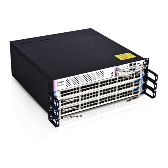
Ruijie RG-S7800C Switches Quick Installation Guide, V1.2 Product Overview 1 Product Overview Launched by Ruijie independently, RG-S7800C series next generation core switches adopt the Crossbar/FULLMESH architecture. RG-S7800C series switches support dual supervisor modules and power supply redundancy. There are two models available: ... -
Page 5: Safety Precautions For Movement
Safety Precautions for Movement 2 Safety Precautions for Movement RG-S7800C series switches are large and heavy. When you move them, please pay attention to the following requirements: Unplug all power cords before you move the switch. Note: There may be more than one power cord. -
Page 6: Preparations Before Installation
Ruijie RG-S7800C Switches Quick Installation Guide, V1.2 Preparations Before Installation 3 Preparations Before Installation 3.1 ESD Prevention Precaution To avoid the damages from static electricity to the internal parts of switches, do as follows: ESD prevention measures are taken in the sites where switches are installed. ... -
Page 7: Installation Site
3.2 Installation Site RG-S7800C series must be used in the room. To ensure normal operation and a prolonged use life of the device, the installation site must meet the requirements of weight capacity, humidity , cleanness, EMI consideration, grounding system, power, and ventilation. -
Page 8: Installation Tools
RG-S7800C Switch Quick Installation Guide, V1.2 Preparations Before Installation Be sure that the slide rail in the cabinet is enough to bear the weight of a RG-S7800C and its installation accessories. Be sure that the cabinet provides an earthing terminal for the switch to be grounded. ... - Page 9 RG-S7800C Switch Quick Installation Guide, V1.2 Preparations Before Installation 3.6 Unpacking Package Checklist Device panels are installed and operational. Chassis Carton Fans, screwdriver, anti-static wrist strap, yellow/green grounding wires, quick installation guide, packing list Module Carton Modules, packing list, documentation A normal delivery should contain the above mentioned items, which may differ from the actual delivery, depending on purchase contracts.
-
Page 10: Installing The Switch
Ruijie RG-S7800C Switches Quick Installation Guide, V1.2 Installing the Switch 4 Installing the Switch 4.1 Installation Flowchart Figure 4-1 Installation Flowchart 4.2 Installing Slide Rails When installing slide rails for the RG-S7800C, ensure that the plane to carry the chassis should be installed on the plane of delimiters of 1 RU, as shown in Figure 4-2. -
Page 11: Installing The Air Filter (Optional)
RG-S7800C Switch Quick Installation Guide, V1.2 Installing the Switch Note: ① and ② represents 1 RU delimiters. Before installing a slide rail, please verify that it is firm enough to bear the device weight and its installation accessories. There are variable kinds of slide rails. The rail appearance and installation is subject to actual conditions. In order to keep the cabinet balanced, please install the slide rail to as low a position as possible in the cabinet if only one RG-S7800C switch is installed. - Page 12 Figure 4-4 Installing the Air Filter of the Supervisor Module and Service Module on RG-S7808C Switch 4.4 Installing External PoE Power Frame (Optional) The PoE power frame M78-PSE is an optional accessory for the RG-S7808C. See RG-S7800C Series Switch Installation and Reference Guide for details. The PoE power frame is not supported on the RG-S7805C.
- Page 13 RG-S7800C Switch Quick Installation Guide, V1.2 Installing the Switch 4.5 Mounting Cable Management Bracket Make sure the anti-static wrist strap is grounded well and wear the anti-static wrist strap. The cable management bracket of RG-S7800C is not mounted before delivery. ...
-
Page 14: Mounting The Switch To A Cabinet
Precautions Before mounting RG-S7800C series to the cabinet, first verify that the front and back brackets of the cabinet are at the right locations. If the bracket is too far forward, the front panel of the equipment may be too close to the front door, so that the front door cannot be closed when network cables and fibers are connected. -
Page 15: Connecting The System Ground
RG-S7800C Switch Quick Installation Guide, V1.2 Installing the Switch 4.7 Connecting the System Ground A good grounding system protects your switch against lightning strikes and interferences and ensures its normal operation and reliability. Precautions The sectional area of the grounding wire should be determined according to the possible maximum current. Cables of good conductor should be used. -
Page 16: Installing Power Supplies
RG-S7800C Switch Quick Installation Guide, V1.2 Installing the Switch Figure 4-11 Grounding Point on Rear of RG-S7805C To guarantee the security of the person and the device, the RG-S7800C must be well-grounded. The grounding resistance shall be less than 1Ω. A service person shall check whether or not the socket-outlet from which the equipment is to be powered provides a connection the building protective earth. - Page 17 RG-S7800C Switch Quick Installation Guide, V1.2 Installing the Switch The RG-S7805C power system provides two power supply slots. It is recommended that you configure1+1 power supply redundancy. When RG-S7808C/RG-S7805C is powered up by more than one source, the power must be in the same model. If you want to carry or lift the power module, please hold the bottom of the module with your hand instead of carrying the module by the handle.
-
Page 18: Installing Fans
The host power is the summation of the power of all working modules, including the supervisor module, service module and fan. For the power of each module, see RG-S7800C Series Switches Installation and Reference Guide. 4.9 Installing Fans The fan tray model of the RG-S7808C and RG-7805C is M08-FAN and M05C-FAN respectively. -
Page 19: Installing Modules
RG-S7800C Switch Quick Installation Guide, V1.2 Installing the Switch Figure 4-15 Installing M05C-FAN Do not remove the fan tray forcibly. You can use the fan handle. Otherwise, component damage may occur, which causes deformation of the fan tray, and the fan tray cannot be removed. 4.10 Installing Modules Always wear an anti-static wrist strap when installing the module and the metallic part of the anti-static wrist strap should be fully touched with the skin. - Page 20 RG-S7800C Switch Quick Installation Guide, V1.2 Installing the Switch ① Supervisor module slot ② Service module slot Note: Figure 4-17 Slot Location on RG-S7805C ① Supervisor module slot ② Service module slot Note: Install Modules The supervisor module and service module adopt the design of self-locking lever. See figure 4-13 for operation. (1) Lever Operation Figure 4-18 Pulling out Lever (2) Module Installation on RG-S7808C...
-
Page 21: Connecting The Power Cord
RG-S7800C Switch Quick Installation Guide, V1.2 Installing the Switch If a slot is not inserted with a supervisor module, or service module, please cover the slot with a filler panel for heat dissipation. (3) Module Installation on RG-S7805C Pull out both levers (①... -
Page 22: Installation Verification
Verify that the fan meets the requirement. See RG-S7800C Series Hardware Installation and Reference Guide for details. Verify that the power supply is properly selected. See RG-S7800C Series Hardware Installation and Reference Guide for details. Verify that the power module is inserted properly and the screws are fastened tightly. - Page 23 RG-S7800C Switch Quick Installation Guide, V1.2 Installing the Switch Verify that all power supplies are turned off if you want to turn off the power. Verify that the power cord is connected properly and won’t be loosened. Verify that the power cord is long enough to avoid being stretched.
-
Page 24: Logging In To The Switch
LEDs. Module LED Indicator Status Supervisor Module Status Solid green Service Module Status Solid green Power Supply Status Solid green Status Solid green For the detailed description of LEDs, see RG-S7800C Series Switches Hardware Installation and Reference Guide.
Need help?
Do you have a question about the RG-S7800C Series and is the answer not in the manual?
Questions and answers