Table of Contents
Advertisement
Quick Links
Advertisement
Table of Contents

Subscribe to Our Youtube Channel
Related Manuals for Ruijie Networks RG-S2628G-I


Summary of Contents for Ruijie Networks RG-S2628G-I
- Page 1 RG-S2600G-I Series Switch Hardware Installation and Reference Guide V1.08...
-
Page 2: Copyright Statement
This document is provided “as is”. The contents of this document are subject to change without any notice. Please obtain the latest information through the Ruijie Networks website. Ruijie Networks endeavors to ensure content accuracy and will not shoulder any responsibility for losses and damages caused due to content omissions, inaccuracies or errors. -
Page 3: Obtaining Technical Assistance
It is intended for the users who have some experience in installing and maintaining network hardware. At the same time, it is assumed that the users are already familiar with the related terms and concepts. Obtaining Technical Assistance Ruijie Networks website: http://www.ruijienetworks.com/ http://webchat.ruijie.com.cn ... -
Page 4: Product Overview
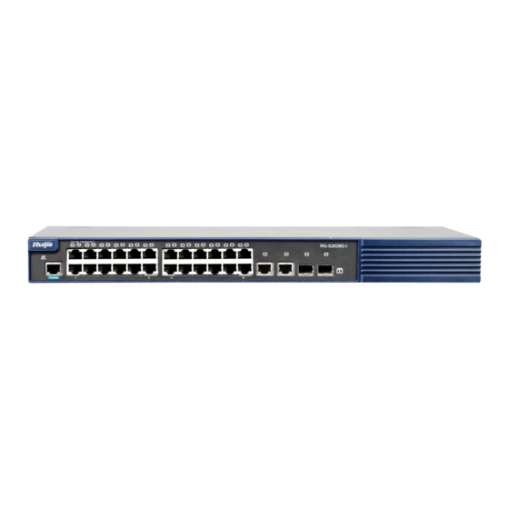
RG-S2600G-I Series Switch Hardware Installation and Reference Guide Product Overview The RG-S2600G-I series switches are the next generation layer-2 switches launched by Ruijie Networks. Integrated with high performance, high security and multiple services, the RG-S2600G-I series switches are mainly applicable to the access layer of large-scale networks to provide full line-rate layer-2 switching and complete QoS policies, and to ensure the undelayed transmission of key data by applying different traffic classification rules to different applications. - Page 5 Dimensions (W x D x H) 3.9 kg Weight RG-S2628G-I switch is a class A product. In a domestic environment, this product may cause radio interference in which case the user may be required to take adequate measures. Product Appearance The front panel of the RG-S2628G-I Ethernet switch provides twenty-four 10/100Base-T Ethernet ports, two Gigabit copper ports, two Gigabit SFP fiber ports and one Console port.
- Page 6 4. 10/100Base-T adaptive Ethernet port 8. 1000Base-X SFP port indicator indicator Back panel Figure 1-3 RG-S2628G-I back panel 1. Grounding rod 3. Cable plug retention clips Note 2. Three-hole AC power receptacle Power Supply The RG-S2628G-I switch adopts the AC power input.
- Page 7 Heat Dissipation The RG-S2628G-I is designed with no fans. To ensure good dissipation, sufficient ventilation space(10 cm distance from both sides and the back panel of the chassis) should be reserved to avoid the air intake of the chassis from being blocked;...
- Page 8 RG-S2600G-I Series Switch Hardware Installation and Reference Guide RG-S2652G-I Model Gigabit Ethernet: Module Type Mini-GBIC-SX Mini-GBIC-LX Mini-GBIC-LH40 Mini-GBIC-ZX50 Mini-GBIC-ZX80 Mini-GBIC-ZX100 1000Base-T: Mini-GBIC-GT SFP stack module GE-SFP-STACK1.6M The supported module type may change at any time. Contact us for the detailed change information.
- Page 9 RG-S2600G-I Series Switch Hardware Installation and Reference Guide RG-S2652G-I switch is a class A product. In a domestic environment, this product may cause radio interference in which case the user may be required to take adequate measures. Product Appearance The front panel of the RG-S2652G-I Ethernet switch provides forty-eight 10/100Base-T Ethernet ports, two Gigabit copper ports, two Gigabit SFP fiber ports and one Console port.
- Page 10 RG-S2600G-I Series Switch Hardware Installation and Reference Guide 1. Grounding rod 3. Cable plug retention clips Note 2. Three-hole AC power connector Power Supply The RG-S2652G-I adopts the AC power input. AC input: Rated voltage range: 100-240 V Maximum voltage range: 90-264 V Frequency: 50/60 Hz Rated current: 0.6 A Power cord specification: 10 A power cord...
- Page 11 RG-S2600G-I Series Switch Hardware Installation and Reference Guide Indicator Faceplate Status Indication Marker the switch immediately. Solid red Indicates a fault on the switch. For details, refer to Section 5.2 Troubleshooting Common Faults. RJ-45 port indicator The port is not connected to a link. 1~50 Solid green The link that the port connects to is Up.
-
Page 12: Preparation Before Installation
RG-S2600G-I Series Switch Hardware Installation and Reference Guide Preparation before Installation Safety Suggestions To avoid personal injury and equipment damage, please carefully read the safety suggestions before you install the RG-S2600G-I series. The following safety suggestions do not cover all possible dangers. Safety Precautions for Installing the System ... -
Page 13: Installation Site Requirements
RG-S2600G-I Series Switch Hardware Installation and Reference Guide 2. Direct or indirect touch through a wet object on high-voltage and mains supply may bring a fatal danger. Static Discharge Damage Prevention To prevent damage from static electricity, pay attention to the following: ... -
Page 14: Cleanness Requirements
RG-S2600G-I Series Switch Hardware Installation and Reference Guide In an environment with high relative humidity, the insulating material may have bad insulation or even leak electricity. Sometimes the materials may suffer from mechanical performance change and metallic parts may get rusted. ... -
Page 15: System Grounding Requirements
RG-S2600G-I Series Switch Hardware Installation and Reference Guide The Average refers to the average limit of harmful gas in one week. The Maximum value is the upper limit of the harmful gas measured in one week for up to 30 minutes every day. During applications, the switch may be subject to external interferences that affect the device through conduction manners such as capacitance coupling, inductive coupling, electromagnetic wave emission, common impedance (including grounding systems), and wires (power cables, signal cables and outgoing transmission cables). -
Page 16: Emc Grounding
RG-S2600G-I Series Switch Hardware Installation and Reference Guide EMC Grounding The grounding required for EMC design includes shielding ground, filter ground, noise and interference suppression, and level reference. All the above constitute the comprehensive grounding requirements. The grounding resistance should be less than 1 ohm. -
Page 17: Precaution For Fiber Connections
RG-S2600G-I Series Switch Hardware Installation and Reference Guide the source and the sensitive component, along which cable the interference conducts from one unit to another. Conducted interference often affects the power supply of the equipment, but can be controlled by a filter. Radiated interference may affect any signal path in the equipment and is difficult to shield. -
Page 18: Product Installation
RG-S2600G-I Series Switch Hardware Installation and Reference Guide Product Installation Please ensure that you have carefully read Chapter 2. Make sure that the requirements set forth in Chapter 2 have been met. Installation Procedure Confirmations before Installation Before installation, please confirm the following points: Whether sufficient airflow is available for the switch ... -
Page 19: Mounting The Switch In A Standard 19-Inch Rack
RG-S2600G-I Series Switch Hardware Installation and Reference Guide Connect the power cables of different colors to the corresponding grounding posts. Ensure that the connected power cables have sound contact. Do not place heavy items on the switch. ... -
Page 20: Mounting The Switch On A Table
RG-S2600G-I Series Switch Hardware Installation and Reference Guide Mounting the Switch on a Table Step 1: Attach the four rubber feet to the recessed areas on the bottom of the switch. Step 2: Place the switch on the table. Checking after Installation Before checking the installation, switch off the power supply so as to avoid any personal injury or damage to the component due to connection errors. -
Page 21: System Debugging
RG-S2600G-I Series Switch Hardware Installation and Reference Guide System Debugging Establishing the Configuration Environment Establishing the Configuration Environment Connect the PC to the console port of the switch through the console cable, as shown in Figure 4-1. Figure 4-1 Schematic diagram of the configuration environment Connecting the Console Cable Step 1: Connect one end of the DB-9 jack of the console cable to the serial port of the PC. - Page 22 RG-S2600G-I Series Switch Hardware Installation and Reference Guide Enter the name of the new connection and click OK, the interface as shown in Figure 4-3 is displayed. Choose the serial port used currently in the column [use when connecting]. Figure 4-3 After choosing the serial port, click OK to display the serial port parameter setting interface, set the baud rate to 9600, data bit to 8, parity check to none, stop bit to 1 and flow control to none.
-
Page 23: Power-On Startup
RG-S2600G-I Series Switch Hardware Installation and Reference Guide After setting the parameters, click OK to enter the hyper terminal interface. Power-on Startup Checking before Power-on The switch is fully grounded. The power cable is correctly connected. The power supply voltage complies with the requirement of the switch. ... -
Page 24: Maintenance And Troubleshooting
General Troubleshooting Procedure Troubleshooting Common Faults Symptom Possible Causes Solution Forgetting the management Please contact Ruijie Networks interface login password Customer Service Department for technical support. The status indicator is not on after The power supply module does not Check whether the power socket the switch is started. - Page 25 RG-S2600G-I Series Switch Hardware Installation and Reference Guide Symptom Possible Causes Solution The serial port console has no The serial port connected to the switch Change the serial port opened by output or outputs illegible does not match that opened by the the configuration software to be characters.
-
Page 26: Appendix A: Connectors And Connection Media
RG-S2600G-I Series Switch Hardware Installation and Reference Guide Appendix A: Connectors and Connection Media 1000BASE-T/100BASE-TX/10BASE-T Ports The 1000BASE-T/100BASE-TX/10BASE-T is a port that supports adaptation of three rates, and automatic MDI/MDIX Crossover at these three rates. The 1000BASE-T complies with IEEE 802.3ab, and uses the cable of 100-ohm Category-5 or Supper Category-5 UTP or STP, which can be up to 100 m. - Page 27 RG-S2600G-I Series Switch Hardware Installation and Reference Guide Straight-Through Crossover Switch Switch Switch Switch 1 IRD + 1 OTD + 1 IRD + OTD + 2 IRD - 2 OTD - 2 IRD - OTD - 3 OTD + 3 IRD + 3 OTD + 3 IRD + 6 OTD -...
-
Page 28: Appendix B Mini-Gbic Modules
RG-S2600G-I Series Switch Hardware Installation and Reference Guide Appendix B Mini-GBIC Modules We provide appropriate 1000M SFP modules (Mini-GBIC modules) for different module interfaces of the switch. You can select the SFP module as needed. The following models and technical specifications of some 1000M SFP modules are listed for your reference. Models and Technical Specifications of the Mini-GBIC (SFP) Module Table B-1 Models and Technical Specifications of the SFP Module Modal... - Page 29 RG-S2600G-I Series Switch Hardware Installation and Reference Guide For the optical module with transmission distance exceeding 40 km and more, one on-line optical attenuator should be added on the link to avoid the overload of the optical receiver when short single-mode optical fibers are used.
-
Page 30: Appendix C Site Selection
RG-S2600G-I Series Switch Hardware Installation and Reference Guide Appendix C Site Selection The machine room should be at least 5km away from the heavy pollution source such as the smelter, coal mine and thermal power plant, 3.7km away from the medium pollution source such as the chemical industry, rubber industry and electroplating industry, and 2km away from the light pollution source such as the food manufacturer and leather plant.
Need help?
Do you have a question about the RG-S2628G-I and is the answer not in the manual?
Questions and answers