Table of Contents
Advertisement
Quick Links
Advertisement
Table of Contents

Related Manuals for Ruijie Networks RG-N18014


Summary of Contents for Ruijie Networks RG-N18014
- Page 1 RG-N18000 Series Switches Hardware Installation and Reference Guide V1.08...
-
Page 2: Copyright Statement
This document is provided “as is”. The contents of this document are subject to change without any notice. Please obtain the latest information through the Ruijie Networks website. Ruijie Networks endeavors to ensure content accuracy and will not shoulder any responsibility for losses and damages caused due to content omissions, inaccuracies or errors. - Page 3 Appendix B "Mini-GBIC Modules" Appendix C “Lightening Protection” Appendix D “Cabling Recommendations in Installation” Appendix E “Site Selection” Obtaining Technical Assistance Ruijie Networks website: http://www.ruijienetworks.com/ http://webchat.ruijie.com.cn Online customer services: http://www.ruijie.com.cn/service.aspx Customer service center: ...
- Page 4 Means reader take note. Notes contain helpful suggestions or references. Means reader be careful. In this situation, you might do something that could result in equipment damage or loss of data.
-
Page 5: Product Overview
RG-N18000 series support dual supervisor modules and power supply redundancy, and are available in two models, namely, RG-N18014 and RG-N18010. The RG-N18014: designed with 14 transverse slots, supporting dual supervisor modules and providing 12 service module slots; ... -
Page 6: Product Appearance
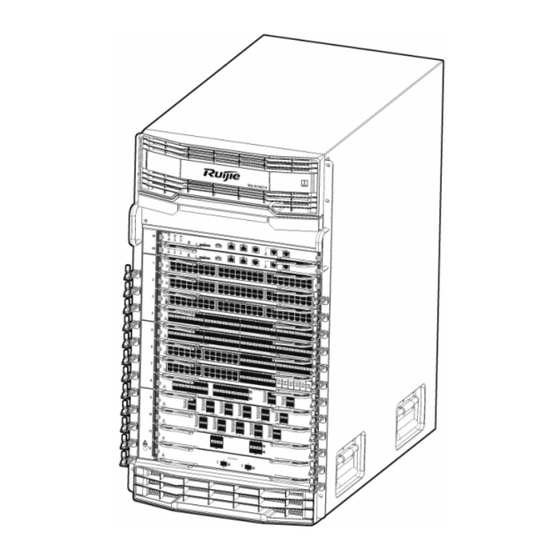
The RG-N18014 switch is an A-class product and may cause radio disturbance to surroundings. In this case, users are advised to take proper measures against the disturbance. Product Appearance The hardware system of the RG-N18014 switch is composed of the chassis, the power system, modules and the cooling system. ... -
Page 7: Front Panel
Front Panel The front panel of the RG-N18014 switch is shown in Figure 1-2. Figure 0-2 Front Panel of the RG-N18014 Switch... -
Page 8: Back Panel
Ensure the supervisor module, service module, switch fabric module and power supply module are removed from the chassis before you move or transport the RG-N18014 chassis. Back Panel The back panel of the RG-N18014 switch is shown in Figure 1-3. Figure 0-3 Back Panel of the RG-N18014 Switch... -
Page 9: Power Supply
AC power supply input: The RG-PA1600I and the RG-PA600I power supply modules are supported. The two types of power supply modules support power management. The supervisor module of the RG-N18014 switch can read the power supply information and implement flexible and intelligent power management. - Page 10 According to the thermal design of the RG-N18014 switch, fans are used to draw air for forced convection cooling in order to ensure that the device works properly in the specified environment.
- Page 11 Note: Exhaust vents for power modules Exhaust vents for switch fabric modules Exhaust vents for service and supervisor modules For the supervisor and service modules, air flows across the chassis from the right intakes to the back vents. For the power supply modules, air flows in from the front intakes and out from the back vents.
- Page 12 RG-N18010 Specifications Model RG-N18010 Module Slot Two supervisor module slots, eight service module slots and four switch fabric module slots M18010-CM Supervisor Module M18010-CM II M18010-FE-D I M18010-FE-C I Switch Fabric Module M18010-FE-D III M18000-24GT20SFP4XS-ED M18000-48GT-ED M18000-48GT-P-ED M18000-44SFP4XS-ED M18000-44SFP4XS-CB M18000-08XS-ED M18000-16XS-CB M18000-48XS-DB M18000-40XS-CB...
- Page 13 The weight only includes that of the empty chassis and fans. The whole device's weight is subject to that of the modules selected. The RG-N18010 switch is an A-class product and may cause radio disturbance to surroundings. In this case, users are advised to take proper measures against the disturbance.
- Page 14 Front Panel The front panel of the RG-N18010 switch is shown in Figure 1-7. Figure 0-7 Front Panel of the RG-N18010 Switch...
- Page 15 Note: Cable management bracket Handle Supervisor module slots Fan tray of the switch fabric module Service module slots Anti-static wrist strap socket Plastic cover for the air filter of the ⑧ Plastic cover for the power module service module Ensure the supervisor module, service module, switch fabric module and power supply module are removed from the chassis before you move or transport the RG-N18010 chassis.
- Page 16 Note: Power module slots PoE power modules slots Captive screws of the fan tray Fan tray handle Switch fabric modules slots Fans of service module and Grounding point supervisor module ⑧ Anti-static wrist strap socket Power Supply ...
- Page 17 Heat Dissipation Solution The operating environment temperature of RG-N18010 switches ranges between 0 and 50°C. The heat dissipation design must satisfy the requirement on the device's reliability in the temperature range while ensuring the device's safety and maintainability. The supervisor and service modules use fans to draw air and the switch fabric module uses fans to blow air for forced convection in order to ensure that the device works properly in the specified environment.
- Page 18 Note: Exhaust vents for power modules Exhaust vents for service and supervisor modules Exhaust vents for switch fabric modules For supervisor and service modules, air flows in from the front intakes and out from the upper vents. ...
-
Page 19: Module Appearance
The modules of the RG-N18000 switch provide 10/100/1000M auto-sensing Ethernet copper ports, 1000 Mbps/100 Mbps SFP (single-mode/multi-mode) optical fiber interfaces and 10G/40G optical fiber interfaces. M18014-CM M18014-CM is the supervisor module of the RG-N18014 series switches and is designed with management and switching functions. Module Appearance... - Page 20 In case of a short press, the Status LED flashes in green, and the device resets within five seconds after the press. In case of a long press, the Status LED flashes in green and then flashes in red; the device resets within five seconds after the press.
- Page 21 The M18014-CM adopts the CR2032 lithium battery. The device may explode if a wrong battery model is used. Used batteries should be properly disposed of. M18014-CM M18014-CM is the supervisor module of the RG-N18014 series switches and is designed with management and switching functions. Module Appearance Figure 0-12 Appearance of the M18014-CM...
- Page 22 To secure data and prevent damage to the device, it is recommended to use high-quality SD memory cards produced by reliable manufacturers. The SD card slot is compatible with most SD memory cards but may be unable to identify some SD memory cards. Console port: As a serial communications port, it uses the RS-232 interface level and standard RJ-45 connector.
- Page 23 Solid red The fan is faulty. Power status LED The power supply module is NOT in the position. Solid green The power supply module is operational. Solid red The power supply module is faulty. MGMT port status LED None The MGMT port is NOT connected. Green The MGMT port is connected at 1000Mbps.
- Page 24 External Port The M18010-CM module provides five external ports: USB port: By connecting to the USB port, USB storage devices can store logs, host version, alarms and other diagnosis information, facilitating online upgrade of switch software and storage of logs. To secure data and prevent damage to the device, it is recommended to use high-quality flash disks produced by reliable manufacturers.
- Page 25 errors. Solid green The module is operational The module acts as the standby supervisor module. Primary/standby supervisor Primary module LED Solid green The module acts as the primary supervisor module. No fault The system fails, interrupting functioning of the whole Solid red system or a module;...
- Page 26 Temperature Storage -40 to 70°C Temperature Operating Humidity 10% to 90% RH (non-condensing) MTBF 329,000 hours Weight Net weight: 1.68 kg Dimensions 199 mm x 440 mm x 29.98 mm (W x D x H) The M18010-CM adopts the CR2032 lithium battery. The device may explode if a wrong battery model is used.
- Page 27 In case of a short press of the button, the Status LED flashes in green, and the device resets within five seconds. In case of a long press, the Status LED flashes in green and then flashes in red; the device resets within five seconds.
- Page 28 SDRAM DDRIII 16 GB One Console port, One 10/100/1000M MGMT port; External Port One SD card slot; One USB port Button One Reset button Power Consumption <102W Hot Swapping Supported Management Supported Redundancy EMC Standards GB9254-2008 CLASS A Safety Standards GB4943-2011 Operating 0 to 50°C...
- Page 29 Solid green The module is operational System temperature exceeds the alarm Solid yellow temperature, affecting system performance. But the system continues running. The port link is NOT connected. Solid green The port is connected at 1000Mbps. GT port LED Link/ACT Solid yellow The port is connected at 10/100Mbps.
- Page 30 Operating 0 to 50°C Temperature Storage -40 to 70°C Temperature Operating 10%-90% RH (non-condensing) Humidity MTBF 305,000 hours Weight Net weight: 3.76 kg Dimensions 399 mm x 440 mm x 40.18 mm (W x D x H) M18000-48GT-ED Module Appearance Figure 0-8 Appearance of the M18000-48GT-ED Module External Port M18000-48GT-ED provides 48 copper ports.
- Page 31 Power Consumption <95W EMC Standards GB9254-2008 CLASS A Safety Standards GB4943-2011 Operating 0 to 50°C Temperature Storage -40 to 70°C Temperature Operating Humidity 10%-90% RH (non-condensing) MTBF 293,000 hours Weight Net weight: 3.70 kg Dimensions 399 mm x 440 mm x 40.18 mm (W x D x H) M18000-48GT-EF Module Appearance...
-
Page 32: Poe Power Supply
Power Consumption <125W EMC Standards GB9254-2008 CLASS A Safety Standards GB4943-2011 Operating 0 to 50°C Temperature Storage -40 to 70°C Temperature Operating Humidity 10%-90% RH (non-condensing) MTBF 290,000 hours Weight Net weight: 3.80 kg Dimensions 399 mm x 440 mm x 40.18 mm (W x D x H) M18000-48GT-P-ED Module Appearance... - Page 33 Press the “Mode” button to change the mode between switching and PoE. The green LED indicates switching mode and the yellow LED indicates PoE mode. In PoE mode, hold down the “Mode” button for three seconds to disable PoE power supply and switch to switching mode.
- Page 34 The module is NOT receiving power. Solid red The module is faulty. High temperature alarm. The system keeps operating Solid yellow System LED Status but the performance is affected. Blinking Initialization is in progress. Continuous blinking green indicates errors. Solid green The module is operational The port link is NOT connected.
- Page 35 Module Appearance Figure 0-20 Appearance of the M18000-44SFP4XS-EF Module External Port It provides 44 SFP ports and four SFP+ ports. The SFP ports support the rate of 100/1000 Mbps, the SFP+ ports support 10G SFP+ modules and Gigabit SFP modules. Hot swapping of the M18000-44SFP4XS-EF, SFP and SFP+ modules is supported.
- Page 36 XG-SFP-CU5M 5m SFP+ copper cables (DAC) Status, Link/ACT Hot Swapping Supported Power <175W Consumption EMC Standards GB9254-2008 CLASS A Safety GB4943-2011 Standards Operating 0 to 50°C Temperature Storage -40 to 70°C Temperature Operating 10%-90% RH (non-condensing) Humidity MTBF 299,000 hours Weight Net weight: 3.86 kg Dimensions...
- Page 37 BOOTROM 8 MB Flash Memory 512 MB SDRAM DDRIII 1GB Port Type Eight SFP+ ports supporting 10G SFP+ modules and 1G SFP modules 1000BASE-SX (850nm) Multi-mode optical fiber 1000BASE-LX (1310nm) Single-mode optical fiber 1000BASE-LH (1310nm) Single-mode optical fiber 1000BASE-ZX(1550nm) Single-mode optical fiber 10GBASE-SR (850nm) Multi-mode optical fiber Transmission...
- Page 38 Initialization is in progress. Continuous blinking Blinking green indicates errors. Solid green The module is operational The port link is NOT connected. SFP+ port LED Link/ACT Solid green The port is connected. Blinking The port is transmitting and receiving data. Specifications Model M18000-08XS-EF...
- Page 39 The M18000-48XS-DB supports 10G SFP+ and Gigabit SFP modules. 10G SFP+ modules cannot be used as Gigabit SFP modules. Identification on Status Meaning the panel The module is NOT receiving power. Solid red The module is faulty. Initialization is in progress. Continuous blinking Blinking green indicates errors.
- Page 40 Figure 0-25 Appearance of the M18000-24QXS-DB Module External Port It provides 24 QSFP+ ports supporting 40-Gigabit QSFP+ modules. Hot swapping of the 18000-24QXS-DB and QSPF+ modules is supported. Identification on Status Meaning the panel The module is NOT receiving power. Solid red The module is faulty.
- Page 41 External Port The M18000-12QXS-DB provides 12 QSFP+ ports. The QSFP+ ports support 40-Gigabit QSFP+ modules. Hot swapping of the M18000-12QXS-DB and QSFP+ modules is supported. Identification on Status Meaning the panel The module is NOT receiving power. Solid red The module is faulty. Initialization is in progress.
- Page 42 External Port The M18000-24XS4QXS-DB provides 24 SFP+ ports and four QSFP+ ports. The SFP+ ports support 10G SFP+ modules and Gigabit SFP modules. QSFP+ ports support 40-Gigabit QSFP+ modules. Hot swapping of the M18000-24XS4QXS-DB, SFP, SFP+ and QSFP+ modules is supported. The M18000-24XS4QXS-DB supports 10G SFP+ and Gigabit SFP modules.
- Page 43 Power <208W Consumption EMC Standards GB9254-2008 CLASS A Safety Standards GB4943-2011 Operating 0 to 50°C Temperature Storage -40 to 70°C Temperature Operating Humidity 10%-90% RH (non-condensing) MTBF 316,000 hours Weight Net weight: 4.0 kg Dimensions 399 mm x 440 mm x 40.18 mm (W x D x H) M18000-44SFP4XS-CB Module Appearance...
- Page 44 1000BASE-ZX (1550nm) Single-mode optical fiber 10GBASE-SR (850nm) Multi-mode optical fiber 10GBASE-LR (1310nm) Single-mode optical fiber 10GBASE-ER (1550nm) Single-mode optical fiber 10GBASE-ZR (1550nm) Single-mode optical fiber XG-SFP-CU1M 1m SFP+ copper cables (DAC) XG-SFP-CU3M 3m SFP+ copper cables (DAC) XG-SFP-CU5M 5m SFP+ copper cables (DAC) 100BASE-FX is not supported Status, Link/ACT Hot Swapping...
- Page 45 green indicates errors. Solid green The module is operational The port link is NOT connected. SFP+ port LED Link/ACT Solid green The port is connected. Blinking The port is transmitting and receiving data. Specifications Model M18000-16XS-CB Quad-core CPU, each core with the clock speed of 1.0G BOOTROM Flash Memory 512MB...
- Page 46 M18000-40XS-CB supports 10G SFP+ and Gigabit SFP modules. 10G SFP+ modules cannot be used as Gigabit SFP modules. Identification Status Meaning on the panel The module is NOT receiving power. Solid red The module is faulty. High temperature alarm. The system keeps operating Solid yellow System LED Status...
- Page 47 M18000-16XT-CB Module Appearance Figure 0-32 Appearance of the M18000-16XT-CB Module External Port It provides 16 10G RJ45 ports. The RJ45 ports support 100M/1G/10G auto-negotiation, and full duplex only. Identification Status Meaning on the panel The module is NOT receiving power. Solid red The module is faulty.
- Page 48 M18000-10QXS-CB Module Appearance Figure 0-33 Appearance of the M18000-10QXS-CB Module External Port It provides 10 QSFP+ ports. The QSFP+ ports support 40G QSFP+ modules working in 40G mode. Hot swapping of the M18000-10QXS-CB, and QSFP+ modules is supported Identification Status Meaning on the panel The module is NOT receiving power.
- Page 49 RG-WALL 1600-B-ED Module Appearance Figure 0-34 Appearance of the RG-WALL1600-B-ED Module External Port It provides two SFP+ ports. The SFP+ ports support 10G SFP+ modules and Gigabit SFP modules. Hot swapping of the RG-WALL1600-B-ED, SFP and SFP+ modules is supported. RG-WALL1600-B-ED supports 10G SFP+ and Gigabit SFP modules.
- Page 50 Hot Swapping Supported Power Consumption <190W EMC Standards GB9254-2008 CLASS A Safety Standards GB4943-2011 Operating 0 to 50°C Temperature Storage -40 to 70°C Temperature Operating Humidity 10%-90% RH (non-condensing) MTBF 248,000 hours Weight Net weight: 4.58 kg Dimensions 399 mm x 440 mm x 40.18 mm (W x D x H) M18014-FE-C I Module Appearance...
- Page 51 EMC Standards GB9254-2008 CLASS A Safety Standards GB4943-2011 Operating 0 to 50°C Temperature Storage -40 to 70°C Temperature Operating Humidity 10% to 90% RH (non-condensing) MTBF 471,000 hours Weight Net weight: 3.54 kg Dimensions 541 mm x 270 mm x 42.68 mm (W x D x H) M18014-FE-C II Module Appearance...
- Page 52 Operating 0 to 50°C Temperature Storage -40 to 70°C Temperature Operating Humidity 10% to 90% RH (non-condensing) MTBF 422,000 hours Weight Net weight: 4.22 kg Dimensions 541 mm x 270 mm x 42.68 mm (W x D x H) M18014-FE-D I Module Appearance Figure 0-37 Appearance of the M18014-FE-D I Module External Port...
- Page 53 Temperature Operating Humidity 10% to 90% RH (non-condensing) MTBF 421,000 hours Weight Net weight: 3.76 kg Dimensions 541 mm x 270 mm x 42.68 mm (W x D x H) M18014-FE-D III Module Appearance Figure 0-38 Appearance of M18014-FE-D III Module External Port The M18014-FE-D III provides one external port: ...
- Page 54 Temperature Operating Humidity 10% to 90% RH (non-condensing) MTBF 319,000 hours Weight Net weight: 4.56 kg Dimensions 541 mm x 270 mm x 42.68 mm (W x D x H) M18010-FE-C I Module Appearance Figure 0-39 Appearance of the M18010-FE-C I Module External Port The M18010-FE-C I module provides one external port: ...
- Page 55 Temperature Operating Humidity 10% to 90% RH (non-condensing) Weight Net weight: 2.72 kg Dimensions 391 mm x 270 mm x 42.68 mm (W x D x H) M18010-FE-D III Module Appearance Figure 0-40 Appearance of the M18010-FE-D III Module External Port The M18010-FE-D III module provides one external port: Console port: As a serial communication port, it uses the RS-232 interface level and standard RJ-45 connector.
- Page 56 Storage Temperature -40 to 70°C Operating Humidity 10% to 90% RH (non-condensing) MTBF 390,000 hours Weight Net weight: 3.36 kg Dimensions 391 mm x 270 mm x 42.68 mm (W x D x H) M18010-FE-D I Module Appearance Figure 0-41 Appearance of the M18010-FE-D I Module External Port The M18010-FE-D I module provides one external port: ...
- Page 57 Figure 0-42 Appearance of the RG-PA1600I Module External port The RG-PA1600I module provides 12 VAC input to the overall system of the RG-N18014/N18010 switch. The front panel of the power supply module provides a 3-pin power port, which can be connected to standard 16A power cord.
- Page 58 Figure 0-43 Appearance of the RG-PA600I Module External Port The RG-PA600I module provides 12 VAC input to the overall system of the RG-N18014/N18010 switch. The front panel of the power supply module provides a 3-pin power port, which can be connected to standard 10A power cord.
- Page 59 Max Power 90 to180 VAC Power: 600 W Output 180 to 264 VAC Power: 600 W High Current DC 192 to 288VDC Power: 600 W Parameter Weight Net weight: 1.64 kg Power Cord 10A power cord Requirement When you plug in the power cord, please fasten the anti-loose buckle to the power cord to prevent loosening. RG-PA1600I-P Module Appearance Figure 0-44 Appearance of the RG-PA1600I-P Module...
- Page 60 Note: PoE power module slot PoE 3-pin power port System power module slot RG-PA1600I-P applies to the host installed with an earlier version than 1.20. Do not insert the PoE power supply into the system power module slot. Do not connect the PoE power cord to the system power supply.
- Page 61 Specifications Module Model RG-PA1600I-P Rated Voltage 100 to 120 VAC, 200 to 240 VAC; 50/60 Hz Range Max Voltage 90 to 264 VAC; 47 to 63 Hz Range Max Power 90 to 175 VAC Power: 1000 W Output 176 to 264 VAC Power: 1600 W Weight Net weight: 1.60 kg Power Cord...
- Page 62 Note: PoE power module slot PoE 3-pin power port System power module slot RG-PA1600I-PL applies to the host installed with version 1.20 and later. Do not insert the PoE power supply into the system power module slot. Do not connect the PoE power cord to the system power supply.
- Page 63 Module Model RG-PA1600I-PL Rated Voltage 100 to 120 VAC, 200 to 240 VAC; 50/60 Hz Range Max Voltage 90 to 264 VAC; 47 to 63 Hz Range Max Power 90 to 175 VAC Power: 1000 W Output 176 to 264 VAC Power: 1600 W Weight Net weight: 1.60 kg Power Cord...
- Page 64 Note: PoE power module slot PoE 3-pin power port System power module slot RG-PA3000I-PL applies to the host installed with version 1.20 and later. Do not insert the PoE power supply into the system power module slot. Do not connect the PoE power cord to the system power supply.
- Page 65 Module Model RG-PA3000I-PL Rated Voltage 100 to 120 VAC, 200 to 240 VAC; 50/60 Hz Range Max Voltage 90 to 264 VAC; 47 to 63 Hz Range Max Power 90 to 175 VAC Power: 1000 W Output 176 to 264 VAC Power: 1600 W Weight Net weight: 1.60 kg Power Cord...
- Page 66 Solid green Solid red Output overcurrent protection Solid green Solid orange Temperature alarm Solid green Solid red Over-temperature protection Solid green Solid red PSR on/off Solid green Solid red Phase loss protection Solid green Solid red Fan failure Specifications Module Model RG-PD1600I Rated Voltage -48 VDC...
- Page 67 Meaning Solid green Solid green The module is operational There is external power supply. The power module is not in Solid green Solid red use. There is no external power supply. The power module is in Solid red use. Solid red Overcurrent Solid green Solid red...
- Page 68 Composition The M14-FAN is the fan for service modules, supervisor modules and switch fabric modules on the RG-N18014. There are five M14-FAN trays, each with four 120 mm x 120 mm x 38 mm fans and one fan control board. The M14-FAN draws air out to form convection for heat dissipation.
- Page 69 Note: Captive screws of the fan tray Fan handle Fan status LED Composition The M10-FAN-R is the fan for service modules and supervisor modules on the RG-N18010. There are three M10-FAN-R trays, each with four 120 mm x 120 mm x 38 mm fans and one fan control board. The M10-FAN-R draws air out to form convection for heat dissipation.
- Page 70 M10-FAN-F Module Appearance Figure 0-54 Appearance of the M10-FAN-F Module Note: Fan status LED Fan handle Captive screws of the fan tray Composition The M10-FAN-F is the fan for switch fabric modules on the RG-N18010. There are one M10-FAN-R trays with six 80 mm x 80 mm x 38 mm fans and one fan control board.
- Page 71 Features Function Meaning Status Monitoring Rotational speed monitoring, failure alarm Automatic Speed-adjustment controlled by temperature Speed-adjustment Hot Swapping Hot swapping is supported by the fan tray.
-
Page 72: Preparation Before Installation
Preparation before Installation Safety Suggestions To avoid body injury and equipment damage, please carefully read the safety suggestions before you install RG-N18000. The following safety suggestions do not cover all possible dangers. General Suggestions Take security measures (such as wearing an anti-static wrist strap) to ensure safety. Keep the chassis clean, free from any dust. -
Page 73: Static Discharge Damage Prevention
The N18000 series switches are equipped with an anti-static wrist strap. For the RG-N18014 and RG-N18010 switches, the anti-static wrist strap socket locates at the lower-right corners of the front and back panels. -
Page 74: Laser Safety
Figure 2-2 Preventing EMI on RG-N18010 Laser Safety Among the modules supported by RG-N18000, there are a great number of optical modules that are Class I laser products. Precautions:... -
Page 75: Installation Site Requirements
Ventilation Requirements See RG-N18014 and RG-N18010 in Product Overview for their heat dissipation and ventilation respectively. Sufficient space (10 cm at least) must be reserved at the air intakes and exhaust vents for ventilation. After connecting various cables, you should bundle the cables or place them in the cable management bracket to avoid blocking air intakes. -
Page 76: Cleanness Requirements
On the other hand, in an environment with low relative humidity, the insulating strip may dry and shrink, and static electricity may occur easily and endanger the circuit on the equipment. Humidity Requirements of the RG-N18000 Operating Humidity Storage Humidity 10% to 90% (non-condensing) 5% to 95% (non-condensing) The ambient humidity is measured at the point that is 1.5m above the floor and 0.4m before the equipment... -
Page 77: Power Requirements
Power Requirements When the RG-N18000 can use the following power supplies: RG-PA1600I and RG-PA600I power modules adopt 90 to 264 VAC/ 47 to 63 Hz input. RG-PD1600I and RG-PD600I power modules adopt -40.5 to -75V DC input. Input power shall be larger than the actual power consumption of entire system. For example, the N18014 chassis is installed with two M18014-CM , two M18000-48XS-DB and two M18014-FE-D I modules, the total... - Page 78 The RG-N18000 provides N+M redundancy of power supply. You are recommended to use multiple power supplies for the equipment to ensure its continuous and stable operation by avoiding the impact of unexpected power failures on the equipment. When the dual power supply is applied, the type of the power supply should be identical. System Grounding Requirements A good grounding system is the basis for the stable and reliable operation of the RG-N18000.
-
Page 79: Cabinet Mounting
Cabinet Mounting Make sure the cabinet complies with the following conditions: Install the switch in a 19-inch cabinet in 4-port form hold. Be sure the distance between two square hole strips, one on each side, is 465 mm. Figure 2-3 19-inch Cabinet ... -
Page 80: Installation Tools
Be sure that the slide rail in the cabinet is enough to bear the weight of a RG-N18000 and its installation accessories. Be sure that the cabinet provides an earthing terminal for the switch to be grounded. Be sure that the front and back doors of the cabinet have porosities greater than 50% for good ventilation and heat dissipation. -
Page 81: Unpacking Requirements
Unpacking Requirements Goods Checklist Device panels are installed and operational. Chassis Carton Fans, screwdriver, anti-static wrist strap, yellow/green grounding wires, quick installation guide, packing list Modules, packing list, documentation Module Carton A normal delivery should contain the above mentioned items, which may differ from the actual delivery, depending on purchase contracts. -
Page 82: Product Installation
Product Installation RG-N18000 series Ethernet switch must be used and fixed in the room. Make sure you have carefully read part 2 and this part, and be sure that the requirements set forth in part 2 have been met. Installation Procedure Installation Verification The RG-N18000 is complicated equipment, so you must carefully plan and arrange the installation location, networking mode, power supply, and wiring before installation. -
Page 83: Installing The Air Filter (Optional)
If an air filter is used for a long time, dust may block its air vent, weakening system ventilation. It is recommended you wash the air filter every three months. Installing the Air Filters of the Supervisor Module and Service Module (1) RG-N18014 Figure 3-1 Air Filter Location of the Supervisor Module and Service Module on RG-N18014 Switch... - Page 84 Pull out the filler panel of the air filter. Insert the air filter along the slide rail. Note the direction identifier to ensure the correct direction. Figure 3-2 Installing the Air Filter of the Supervisor Module and Service Module on the RG-N18014 Switch ...
- Page 85 Figure 3-4 Moving forward the Front Limits Figure 3-5 Moving toward the Back Limits (2) RG-N18010 Figure 3-6 Air Filter Location of the Supervisor Module and Service Module on RG-N18010 Switch...
- Page 86 Note: Buttons on plastic cover Plastic cover over air filter To install the air filter , follow these steps: Seat the air filter in the plastic cover and tighten screws. Install the plastic cover before the air filter by pressing firmly the two buttons on the both sides of the plastic cover. Figure 3-7 Installing the Air Filter of the Supervisor Module and Service Module on RG-N18010 Switch...
- Page 87 Installing the Air Filters of the Switch Fabric Module (1) RG-N18014 Figure 3-8 Location of the Air Filter of the Switch Fabric Module on RG-N18014 Switch...
- Page 88 Seat the air filter in the plastic cover and tighten screws. Install the plastic cover over the air filter by pressing firmly the two buttons on the both sides of the plastic cover. Figure 3-9 Installing the Air Filter of the Switch Fabric Module on RG-N18014 Switch...
- Page 89 (2) RG-N18010...
- Page 90 Figure 3-10 Location of the Air Filter of the Switch Fabric Module on RG-N18010 Note: Buttons on plastic cover Plastic cover over air filter To install the air filter, follow these steps: Seat the air filter in the plastic cover and tighten screws. Install the plastic cover over the air filter by pressing firmly the two buttons on the both sides of the plastic cover.
-
Page 91: Installing Brackets
Wear the antistatic wrist strap and make sure the antistatic wrist strap is grounded well. The brackets of RG-N18010 and RG-N18014 are installed before delivery, as shown in figure 3-12 and 3-13). If you want to adjust the location of the bracket, see figure 3-14 and 3-15. - Page 92 (2) RG-N18010 bracket (installed before delivery) Figure 3-13 Installing Bracket to Front Chassis Side...
- Page 93 Move the bracket backward (1) RG-N18014 bracket Remove the bracket from the front chassis side. Install the bracket at a backward location, as shown in figure 3-14: Figure 3-14 RG-N18014 Bracket...
- Page 94 (2) RG-N18010 bracket Remove the bracket from the front chassis side. Install the bracket at a backward location, as shown in figure 3-15: Figure 3-15 RG-N18010 Bracket...
-
Page 95: Mounting Cable Management Brackets
Mounting Cable Management Brackets Make sure the antistatic wrist strap is grounded well and wear the antistatic wrist strap. The RG-N18010 cable management bracket is mounted before delivery while RG-N18014 not. See the following steps and figures for installation. ... -
Page 96: Mounting The Cabinet
Mount the cable management bracket for RG-N18010 Take out cable management brackets. Align the screw holes on the cable management bracket (① in figure 3-17) with those on the chassis (② in figure 3-17). Tighten the screws to fasten the cable management bracket, as shown in figure 3-17. Figure 3-17 Mounting the Cable Management Bracket for RG-N18010 Mounting the Cabinet Precautions... -
Page 97: Installation Steps
When you install the cabinet, pay attention to the following: All expansion bolts for fastening the cabinet base to the ground should be installed and tightened in sequence from bottom up (large plain washer, spring washer, and nut), and the installation holes on the base and the expansion bolts should be well aligned. -
Page 98: Mounting The Switch To A Cabinet
Note: representing entire-U delimiters Before installing a slide rail, make sure that the weight capacity of the slide rail meets requirements. The RG-N18000 series switch is available in two models with different heights. There are variable kinds of slide rails. The rail appearance and installation is subject to actual conditions. In order to keep the cabinet balanced, please install the slide rail to as low a position as possible in the cabinet if only one RG-N18000 switch is installed. - Page 99 Place the switch on the slide rail, and drive it smoothly into the cabinet until the front bracket reaches the square hole strip. Align the installation holes on the bracket with the cage nuts on the square hole strip, and mount them with screws. Figure 3-20 Mounting the Switch into the Cabinet...
-
Page 100: Connecting The System Ground
Attach the one end of the grounding wire to the switch with the two screws. Connect the other end of the grounding wire to the grounding wire of the cabinet. Figure 3-21 Grounding Point on the Rear of the RG-N18014 Switch Figure 3-22 Grounding Point on the Rear of the... - Page 101 To guarantee the security of the person and the device, the RG-N18000 must be well-grounded. The grounding resistance shall be less than 1Ω. A service person shall check whether or not the socket-outlet from which the equipment is to be powered provides a connection the building protective earth.
-
Page 102: Installing Power Supplies
It is recommended that you configure power supply redundancy. When RG-N18014/RG-N18010 is powered up by more than one source, the power must be in the same model. If you want to carry or lift the power module, please hold the bottom of the module with your hand instead of carrying the module by the handle. -
Page 103: Installing Fans
Steps for installing the M14-FAN fan tray: Install the fan tray into the fan slot in the rear panel of RG-N18014. Note the direction identifier of the fan tray’s name to ensure the correct direction. Tighten the captive screws on the fan tray with a screwdriver. - Page 104 Steps for installing the M10-FAN-R fan tray: Install the fan tray into the fan slot in the rear panel of RG-N18010. Note the direction identifier of the fan tray’s name to ensure the correct direction. Tighten the captive screws on the fan tray with a screwdriver. The figure of M10-FAN-R fan tray installation is similar to that of M14-FAN fan tray installation.
-
Page 105: Installing Modules
Do not plug/unplug a supervisor module , service module or switch fabric module forcedly, use the ejector. Select Slots For the slot location of the supervisor module, service module and switch fabric module, please see figure 3-26 and 3-28. Select slots (RG-N18014) Figure 3-26 RG-N18014 Chassis... - Page 106 Note: ①Supervisor module slot ②Service module slot ③Switch fabric module slot Select slots (RG-N18010) Figure 3-27 RG-N18010 Chassis Note: ①Service module slot ②Supervisor module slot ③Switch fabric module slot Install modules The supervisor module, service module and switch fabric module adopt the design of self-locking lever. See figure 3-28 for operation.
- Page 107 Hold down the button on the lever (1 in figure 3-28) and then pull out the lever (2 in figure 3-28). Figure 3-28 Pulling out the Lever Figure 3-29 Pulling out the Levers with Both Hands (2) Install modules into slots (RG-N18014) Pull out both levers (① in figure 3-30).
- Page 108 (3) Install modules into slots (RG-N18010) Pull out both levers (① in figure 3-31). Insert the module into the slot along the slide rail and drive it ahead smoothly (② in figure 3-31). Push both levers toward the slot (③ in figure 3-31).
-
Page 109: Installing Swappable Interface Modules (Optional)
Installing Swappable Interface Modules (Optional) Make sure the optical modules connected to both ends of a fiber are the same type while replacing swappable optical modules. Preparation Wear an anti-static wrist strap to your wrist and tighten the lock. Make sure it is properly grounded. Take out the SFP+/SFP/QSFP+ module you want to install from packing bag. -
Page 110: Installing Sfp+ Cables
Do not insert the SFP+/SFP module with a fiber into a slot. Unplug the fiber before installing the module. Installing SFP+ Cables To avoid damaging components due to operation errors, read this section carefully before installing SFP+ cables. To install the SFP+ copper module, do as follows: You can install the SFP+ copper module with power on. Hold the connector of a copper cable module with one hand and carry the cable to the front panel of the switch with the other. -
Page 111: Installing 40-Gigabit Qsfp+ Modules
Take out the SFP+ module you want to install from the packing bag. Plug the SFP+ cable to the SFP+ port through the connector. Pay attention to the proper end for connection. During the operation, make sure that the cable’s bending radius is no less than eight times as much as its diameter. -
Page 112: Installing 40-Gigabit Qsfp+ Cables
It is recommended that you do not insert the QSFP+ module with a fiber into the slot. Unplug the fiber before installing the module. Do not touch the connecting finger on the module. Do not squeeze, bend or fold the optical fiber, which may cause system performance degradation or data loss. Installing 40-Gigabit QSFP+ Cables To avoid damaging components due to operation errors, read this section carefully before installing 40-Gigabit QSFP+ copper cables. -
Page 113: Connecting The Power Cord
Figure 4-34 Connecting the Power Cord Please use the 3-pin power cord. The cross-sectional area of each pin is 1.5 mm or 14 AWG minimum. 16A and 10A power cords are available for the RG-N18014 and RG-N18010 AC power supply. Adopt the proper socket and verify the AC power supply capacity in the machine room. - Page 114 Connect the DC power cords according to the instructions on the panel, which are green with yellow strip (ground wire), blue (-) and red (+) from left to right, as shown in figure 3-41. Fasten the OT terminal of the DC power cord to the connecting terminal with the screwdriver. Figure 3-41 Power Cord Instruction on Chassis Before connecting the power supply, make sure the external power supply matches the power module inside the unit.
- Page 115 Verify that there is no potential danger in the working area, for example, the power supply is not grounded well, or the ground is wet. Please do not place the switch at a damp place to prevent the moisture from entering the switch. ...
-
Page 116: System Debugging
System Debugging Establishing the Configuration Environment Establishing the Configuration Environment If you log in to the switch for the first time, please use the Console port. Connecting the Console Cable Connect one end of the DB-9 jack of the console cable to the serial port of the PC. Connect one end of the console cable RJ45 to the Console port of the switch. - Page 117 In the Connectivity Note window, type the name of the new connection and click OK. A window appears as shown in Figure 4-3. In the Connect Using field, select the serial port you want to use. Figure 0-3 After selecting the serial port, click OK. The Serial Port Parameter Setting window is displayed, as shown in Figure 4-4.
-
Page 118: Power-On Startup
After setting the serial port parameters, click OK. The Hyperterminal window appears.. Power-on Startup Checking Before Power-on The switch is fully grounded. The power cable is correctly connected. The power supply voltage complies with the requirement of the switch. ... -
Page 119: Monitoring And Maintenance
Monitoring and Maintenance RG-N18000 Monitoring Indicators When the RG-N18000 is running, you can monitor the status of each module by inspecting the status LED of the appropriate module. When the Alarm LED of the master supervisor module is red, it means the system has a fault, in which case you can log in to the management software to perform troubleshooting. -
Page 120: Power Supply Maintenance
Replacing Fuses To replace the old fuse wire with the correspondent new one, please contact the technical support representatives of Ruijie Networks. The following table lists the specifications for the module fuses. Module Fuse Slot Number Fuse Specification... -
Page 122: General Installation Troubleshooting Flow
Check the connection of the fibers or cables of various ports Contact Technical Support of Ruijie Networks for hardware Common Troubleshooting Procedures Fault 1: The AC power module does not work. Fault Description: The Status LED of each service module is OFF, the Power LED of the fan tray is OFF, and the fan does not work. - Page 123 Troubleshooting: First place the switches of all the power modules to OFF. Check if the cables of the cabinet have been correctly connected. Check whether the power cables are tightly connected to the cabinet power sockets and power modules. Check whether the power modules are installed correctly.
- Page 124 Check whether the rates of the two sides match and whether the optical fiber type meets requirements. In addition, for ports supporting different rates, check whether rate modes are configured correctly. If above mentioned methods do not take effect, please contact Ruijie Networks for technology assistance.
-
Page 125: Removing, Cleaning And Installing Air Filter
Insert the air filter along the slide rail. Pay attention to the direction instruction on the air filter. Tighten the screws on the air filter with a screwdriver. Figure 7-1 Installing and Removing the Air Filter of RG-N18014 Supervisor and Service Modules ... -
Page 126: Removing, Cleaning And Installing Air Filter For Switch Fabric Module
Install air filter and tighten the screws. Install the plastic cover of the air filter by pressing the buttons on both sides of the plastic cover, The figure of Installing and removing the air filter of RG-N18014 switch fabric module is similar to figure 7-2. ... -
Page 127: Removing Swappable Interface Modules (Optional)
Removing Swappable Interface Modules (Optional) Removing SFP+/SFP Modules Take the following steps to remove SFP/SFP+ modules: Unplug the optical fiber. Turn down the handle of the module until it is horizontal. Pull the tab to take out the SFP/SFP+ module, as shown in figure 7-4. -
Page 128: Removing 40-Gigabit Qsfp+ Cables
Figure 7-7 Removing the QSFP+ Module Equipped with a Pull-tab Latch Precaution Unplug the optical fiber before removing the module. Do not pull out the module forcefully without turning down the handle of the module. Immediately install the dust plug to the module port and the switch fiber port. Removing 40-Gigabit QSFP+ Cables Hold the cable with one hand and grasp the tab to gently pull to release the module from the socket, as shown in figure 7-8: Figure 7-8 Removing the QSFP+ Cable... - Page 129 Drive the levers close to the module, and the module will hit the back panel. The module will be fastened after self-locking of levers. Figure 7-9 Replacing the Module (for RG-N18014) Figure 7-10 Replacing the Module (for RG-N18010)
-
Page 130: Removing Power Modules
In order to ensure the reliability of the system ventilation and heat dissipation performance and address the requirement of the dust-filter, filler panel needs to be installed in the slot where no supervisor module or service module has been installed. If you want to remove the module when the device is electrified, you need to insert the new module or install the filler panel within 10 minutes. -
Page 131: Removing Fans
Note: A: Power modules to be removed B: Power module to be installed Removing Fans Do not touch any bare wire, terminal or the power instruction on the switch. The fan tray supports hot swapping, If you want to remove the fan tray when the switch is operational, do not remove the fan tray until the fan stops rotating, Besides, do not put your hands inside the fan tray. - Page 132 Note: A: Fan modules to be removed B: Fan modules to be installed Figure 7-13 Removing the Fan for RG-N18010 Switch Fabric Module Note: A: Fan modules to be removed B: Fan modules to be installed...
- Page 133 Figures of removing fans for RG-N18014 supervisor, service and switch fabric modules are similar to figure 7-12...
-
Page 134: Connecting The External Port Cables
Cables This chapter describes the precautions and simple steps for cable connection and bundling. See Appendix D cabling Recommendations in Installation for detailed cabling and bundling. Connecting the External Port Cables Precautions Correctly distinguish single-mode and multi-mode fibers and ports. ... -
Page 135: Appendix A Connectors And Media
Appendix A Connectors and Media 1000BASE-T/100BASE-TX/10BASE-T The 1000BASE-T/100BASE-TX/10BASE-T is a 10/100/1000 Mbps auto-negotiation port that supports auto MDI/MDIX. Compliant with IEEE 802.3ab, 1000BASE-T requires Category 5e 100-ohm UTP or STP (STP is recommended) with a maximum distance of 100 meters (328 feet). 1000BASE-T requires all four pairs of wires be connected for data transmission, as shown in Figure A-1 Figure A-1 1000BASE-T Connection 10BASE-T uses Category 3, 4, 5 100-ohm UTP/STP and 1000BASE-T uses Category 5 100-ohm UTP/STP for... -
Page 136: Fiber Connection
Fiber Connection You can choose to use single mode or multimode fibers according to the transceiver module types. Figure A-4 shows connection of fiber cables. Figure A-4 Fiber Connection... -
Page 137: Appendix B Mini-Gbic, 10-Gigabit Sfp+ And 40-Gigabit Qsfp+ Modules Specifications
Appendix B Mini-GBIC, 10-Gigabit SFP+ and 40-Gigabit QSFP+ Modules Specifications Ruijie provides various Gigabit SFP (Mini-GBIC modules), 10-Gigabit SFP+ and 40-Gigabit QSFP+ transceivers for interfaces of modules on the switch. You can select the most suitable SFP, SFP+ or QSFP+ transceivers as needed. This appendix describes the models and specifications of some of the Gigabit SFP, 10-Gigabit and 40-Gigabit QSFP+ transceivers for your reference. - Page 138 (dBm) 62.5 XG-SFP-SR-MM850 -7.5 2000 300m connector) XG-SFP-LR-SM1310 1310 10km -8.2 -10.3 connector) XG-SFP-ER-SM1550 1550 40km -4.7 -11.3 connector) Table B-4 Existing 10-Gigabit SFP+ Copper Cable Models Support Module Conductor Model Connector Length(m) Data Rate(Gb/s) Type diameter(AWG) (Yes/No) XG-SFP-CU1M Passive SFP+ 10.3125 XG-SFP-CU3M...
-
Page 139: Appendix C Switch Lightning Protection
Appendix C Switch Lightning Protection Installing AC Power Arrester (lightning protection cable row) The external lightning protection cable row shall be used on the AC power port to prevent the switch from being struck by lightning when the AC power cable is introduced from the outdoor and directly connected to the power port of the switch. The lightning protection cable row is fixed on the cabinet, operating table or the wall in the machine room using the line buttons and screws. - Page 140 Tear one side of the protection paper for the double-sided adhesive tape and paste the tape to the framework of the Ethernet port arrester. Tear the other side of the protection paper for the double-sided adhesive tape and paste the Ethernet port arrester to the switch framework.
-
Page 141: Appendix D Cabling Recommendations In Installation
Appendix D Cabling Recommendations in Installation When RG-N18000 series switches are installed in standard 19-inch cabinets, route cable bundles upward or downward along the sides of the rack depending on the actual situation in the equipment room. All cable connectors should be placed at the bottom of the cabinet rather than be exposed outside of the cabinet. - Page 142 If cables are to be bent, bind them first but do not tie cable ties within the bend to avoid stress on the cables, which may otherwise cause the wires inside to break, as shown in Figure D-3. Figure D-3 Do Not Tie Cable Ties within the Bend ...
- Page 143 Flat washer Spring washer Note Flat washer When using a stiff cable, fix it near the cable lug to avoid stress on the lug and cable. Do not use self-tapping screws to fasten terminals. Bundle cables of the same type and running in the same direction into groups. Keep cables clean and straight. ...
-
Page 144: Appendix E Site Selection
Appendix E Site Selection The machine room should be at least 5km away from the heavy pollution source such as the smelter, coal mine and thermal power plant, 3.7km away from the medium pollution source such as the chemical industry, rubber industry and electroplating industry, and 2km away from the light pollution source such as the food manufacturer and leather plant.
Need help?
Do you have a question about the RG-N18014 and is the answer not in the manual?
Questions and answers