Table of Contents
Advertisement
Quick Links
Advertisement
Table of Contents

Related Manuals for Ruijie Networks RG-S12006


Summary of Contents for Ruijie Networks RG-S12006
- Page 1 RG-S12000 Series Switch Hardware Installation and Reference Guide V1.32...
-
Page 2: Copyright Statement
This document is provided “as is”. The contents of this document are subject to change without any notice. Please obtain the latest information through the Ruijie Networks website. Ruijie Networks endeavors to ensure content accuracy and will not shoulder any responsibility for losses and damages caused due to content omissions, inaccuracies or errors. -
Page 3: Obtaining Technical Assistance
It is intended for the users who have some experience in installing and maintaining network hardware. At the same time, it is assumed that the users are already familiar with the related terms and concepts. Obtaining Technical Assistance Ruijie Networks website: http://www.ruijienetworks.com/ http://webchat.ruijie.com.cn ... -
Page 4: Chapter 1 Product Introduction
The RG-S12000 is a module-based, high-capacity and multi-service IPv6 10000M-level routing switch developed by Ruijie Networks, providing powerful defense capability based on high performance and capacity. It can be expanded according to users' business needs, satisfying design requirements for putting equal emphasis on service and performance. -
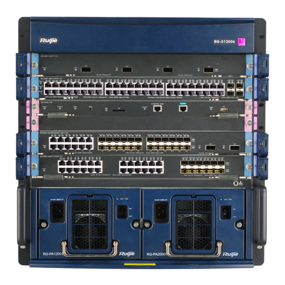
Page 5: Product Appearance
Figure 1-1 Appearance of the RG-S12006 switch Front panel The RG-S12006 switch's front panel is shown in Figure 1-2. See the description for the detailed parts specified by the numbers in the figure. Figure 1-2 Front panel of the RG-S12006 switch... -
Page 6: Back Panel
Back panel The RG-S12006 switch's back panel is shown in Figure 1-3. See the description for the detailed parts specified by the numbers in the figure. Figure 1-3 Back panel of the RG-S12006 switch... -
Page 7: Power Supply
According to the thermal design of the RG-S12000 switch, fans are used to draw air for forced convection cooling in order to ensure that the device works properly in the specified environment. Figure 1-4 Ventilation and heat dissipation system of the RG-S12006 switch... - Page 8 For the host management and service modules, air flows across the chassis from right inlets to back outlets. For the power supply modules, air flows in from front inlets and out from back outlets. Host management and service modules are separated from power supply modules by a division board, which creates two separated air channels.
- Page 9 redundancy Power supply RG-PA1200I: 90-176V- Power: 530W; 176-264V- Power: 1400W module RG-PA1200I: 90-176V- Power: 1080W; 176-264V- Power: 2000W Power supply The power supply redundancy of the same model is supported. redundancy Fan module M12010-FAN I EMC standards GB9254-2008 Safety standards GB4943-2011 Operating 0-50°C...
- Page 10 Front panel The RG-S12010 switch's front panel is shown in Figure 1-6. See the description for the detailed parts specified by the numbers in the figure. Figure 1-6 Front panel of the RG-S12010 switch...
- Page 11 Note: Service module slots Fan tray pull Service module slots Chute Management module slots Static-free wrist strap socket Fan tray Chute Positions where power supplies are installed Anti-dust plastic panel Before the RG-S12010's chassis is moved or transported, management, service and power supply modules must be removed from the chassis.
- Page 12 Back panel The RG-S12010 switch's back panel is shown in the following figure. See the description part for the detailed parts specified by the numbers in the figure. Figure 1-7 Back panel of the RG-S12010 switch Note: Junctions between the chassis and Junctions between the chassis ground and ground...
- Page 13 The operating environment temperature of RG-S12000 switches ranges between 0 and 50°C. The heat dissipation design must satisfy the requirement on the device's reliability in the temperature range while ensuring the device's safety and maintainability. The RG-S12000 switch use fans to draw air for forced convection in order to ensure that the device works properly in the specified environment..
-
Page 14: Module Appearance
M12000-24GT/12SFP-EA M12000-48GT/4SFP-EA M12000P-48GT/4SFP-EA M12000-CM The M12000-CM is the management engine module of the RG-S12000 switches and is designed with management and switching functions. Module Appearance Figure 1-9 Appearance of the M12000-CM External Interface The M12000-CM module provides four external interfaces: ... -
Page 15: Specifications
To secure data and prevent damage to the device, it is recommended to use high-quality SD memory cards produced by reliable manufacturers. The SD interface is compatible with most SD memory cards but may be unable to identify some SD memory cards. Console port: As a serial communications port, it uses the RS-232 interface level and standard RJ-45 connector. - Page 16 BOOTROM Flash Memory 512MB SDRAM One console port for management, one 10/100/1000M MGMT port, one SD port, and one USB External Interface port Button 1 RESET button Power consumption <91W Hot swapping Supported Management Supported redundancy EMC standards GB9254-2008 Safety standards GB4943-2011 Operating 0-50°C...
- Page 17 Console port: As a serial communications port, it uses the RS-232 interface level and standard RJ-45 connector. This port is used to connect the serial port of terminal computers running on the background for such tasks as system debugging, configuration, maintenance, management, and host software loading. ...
- Page 18 port Button 1 RESET button Power consumption <131W Hot swapping Supported Management Supported redundancy EMC standards GB9254-2008 Safety standards GB4943-2011 Operating 0-50°C temperature Storage -40-70°C temperature Operating humidity 10% to 90% RH (non-condensing) Weight Net weight: about 4.8KG Dimensions 436 x 346 x 30 (L x W x H, mm) The M12000-CM III adopts the CR2032 lithium battery.
- Page 19 SFP port is corresponding to a combo 10/100/1000BASE-T port. Only one port can be used at a time. The automatic MDI/MDI-X identification function of the 10/100/1000M electric port takes effect only when auto-negotiation is enabled. The M12000-02XFP24SFP/12GT-EA supports 1000BASE-X and 100BASE-FX modes. Please configure the ports according to the Ruijie Networks configuration manual. M12000-24SFP/12GT-EA Module Appearance...
- Page 20 Figure 1-12 Appearance of the M12000-24SFP/12GT-EA External Interface The M12000-24SFP/12GT-EA provides 12 SFP ports and 12 fiber/copper combo ports. The SFP ports support the rate of 100/1000M, RJ45 ports support auto-negotiation at 10/100/1000 Mbps, and the SFP optical modules support hot swapping.
- Page 21 MDI/MDI-X identification function of the 10/100/1000M electric port takes effect only when auto-negotiation is enabled. The M12000-24SFP/12GT-EA supports 1000BASE-X and 100BASE-FX modes. Please configure the ports according to the Ruijie Networks configuration manual. M12000-48GT/4SFP-EA Module Appearance Figure 1-13 Appearance of the M12000-48GT/4SFP-EA External Interface The M12000-48GT/4SFP-EA provides 44 10/100/1000BASE-T RJ45 ports and four fiber/copper combo ports.
- Page 22 MDI/MDI-X identification function of the 10/100/1000M electric port takes effect only when auto-negotiation is enabled. The M12000-48GT/4SFP-EA supports 1000BASE-X and 100BASE-FX modes. Please configure the ports according to the Ruijie Networks configuration manual. M12000P-48GT/4SFP-EA Module Appearance Figure 1-14 Appearance of the M12000P-48GT/4SFP-EA External Interface It provides 44 10/100/1000BASE-T RJ45 ports and four fiber/copper combo ports.
- Page 23 Blinking The module is being initialized. If it keeps blinking, the green module may be faulty. The initialization has finished and the switch starts Solid green working. Solid green Switching mode Mode LED Mode_Led Solid yellow PoE mode The port link is not up. RJ45 port LED in the Solid green The device is connected to the 1000M port.
- Page 24 The M12000P-48GT/4SFP-EA supports 1000BASE-X and 100BASE-FX modes. Please configure the ports according to the Ruijie Networks configuration manual. The M12000P-48GT/4SFP-EA supports the PoE function, with the maximum out power of 15.4W. If the host is configured with the M12000P-48GT/4SFP-EA line card, the power consumption should be calculated according to the number of PDs and the power consumed by each PD.
- Page 25 MDI/MDI-X identification function of the 10/100/1000M electric port takes effect only when auto-negotiation is enabled. The M12000-24GT/12SFP-EA supports 1000BASE-X and 100BASE-FX modes. Please configure the ports according to the Ruijie Networks configuration manual. M12000-04XFP-EA Module Appearance Figure 1-16 Appearance of the M12000-04XFP-EA External Interface The M12000-04XFP-EA provides four 10000M XFP ports.
- Page 26 medium 10GBASE-LR(1310nm) Single-mode optical fiber 10GBASE-ER(1550nm) Single-mode optical fiber Status, Link/ACT LED Hot swapping Supported Power consumption <100W GB9254-2008 Safety specification GB4943-2011 Operating 0-50°C temperature Storage -40-70°C temperature Operating humidity 10%-90% RH (non-condensing) Weight Net weight: about 3.1KG Dimensions 436 x 346 x 45 (L x W x H, mm) M12000-48XS-DA Module Appearance Figure 1-17 Appearance of the M12000-48XS-DA...
- Page 27 1000BASE-LH40(1310nm) Single-mode optical fiber 1000BASE-ZX(1550nm) Single-mode optical fiber Direct-coupling SFP+ copper cable Status, Link/ACT LED Hot swapping Supported Power consumption <242W EMC standards GB9254-2008 Safety standards GB4943-2011 Operating 0-50°C temperature Storage -40-70°C temperature Operating humidity 10%-90% RH (non-condensing) Weight Net weight: about 5.7KG Dimensions 436 x 346 x 45 (L x W x H, mm) M12000-16XS-DA...
- Page 28 1000BASE-LH40(1310nm) Single-mode optical fiber 1000BASE-ZX(1550nm) Single-mode optical fiber SFP+ copper cable(1m/3m/5m) passive copper cable Status, Link/ACT LED Hot swapping Supported Power consumption <132W EMC standards GB9254-2008 Safety standards GB4943-2011 Operating 0-50°C temperature Storage -40-70°C temperature Operating humidity 10%-90% RH (non-condensing) Weight Net weight: about 5.3KG Dimensions...
- Page 29 Storage -40-70°C temperature Operating humidity 10%-90% RH (non-condensing) Weight Net weight: about 5.1KG Dimensions 436 x 346 x 45 (L x W x H, mm) SECM M12000-NMM SECM M12000-NMM is an agent card that supports network flow monitoring. It can expand the S12000 switches' NMM function.
- Page 30 External Interface The RG-WALL 1600-B-DC module provides two external interfaces: Console port: As a serial communication port, it uses the RS-232 interface level and standard RJ-45 connector. This port is used to connect the module to the serial port of background terminal computers to perform tasks such as firewall commissioning, configuration, maintenance, management, and software loading.
- Page 31 External Interface The RG-WALL 1600-B-DE module provides external interfaces: Console port: As a serial communication port, it uses the RS-232 interface level and standard RJ-45 connector. This port is used to connect the module to the serial port of background terminal computers to perform tasks such as firewall commissioning, configuration, maintenance, management, and software loading.
- Page 32 External Interface The RG-WALL 1600-B-U module provides external interfaces: Console port: As a serial communication port, it uses the RS-232 interface level and standard RJ-45 connector. This port is used to connect the module to the serial port of background terminal computers to perform tasks such as firewall commissioning, configuration, maintenance, management, and software loading.
- Page 33 M12010/M12006-FAN I The M12010-FAN I is the fan module of the RG-S12010; the M12006-FAN I is the fan module of the RG-S12006. The M12010-FAN I/M12006-FAN I provide a reliable heat dissipation system for the entire system to ensure the system's stability.
- Page 34 431.6 x 396.2 x 44 (L x W x H, mm) 312.3 x 298 x 64.4 (L x W x H, mm) RG-PA1200I/RG-PA2000I The RG-PA1200I/RG-PA2000I is the A.C. power supply module, which provides 110/220V A.C. power input for the RG-S12006/S12010. External Interface...
- Page 35 The power supply provides a three-core power supply interface on the front panel and adopts the standard 16A power lead. Identification on Status Definition the panel The power supply is not inputting. Input status LED Solid green The power supply is inputting properly. The power supply is not outputting.
-
Page 36: Chapter 2 Preparation Before Installation
Chapter 2 Preparation Before Installation Safety Suggestions To avoid body injury and equipment damage, please carefully read the safety suggestions before you install RG-S12000. The following safety suggestions do not cover all possible dangers. Safety Precautions for Installing the System ... -
Page 37: Static Discharge Damage Prevention
For the RG-S12010 switch, the anti-static wrist strap hole locates at the lower-right and upper-right corners of the front panel. For the RG-S12006 switch, the anti-static wrist strap hole locates at the lower-right corner of the switch. -
Page 38: Laser Safety
For safety, use a multimeter to measure the resistance between yourself and the ground, which should be within the range of 1–10 Ω. Make sure that the switch is properly grounded when the anti-static wrist trap is connected to the ground through the chassis jack, see 3.8 “Grounding.”... -
Page 39: Ventilation Requirements
Figure 2-2, and 2-3 shows the ventilation requirements of the RG-S12000. Sufficient space (10 cm at least) must be reserved at the air intakes and exhaust vents for ventilation. After connecting various cables, you should bundle the cables or place them in the cabling rack to avoid blocking air inlets. Figure 2-2 RG-S12006 ventilation Figure 2-3 RG-S12010 ventilation... -
Page 40: Temperature And Humidity Requirements
Remove all foam packaging materials and protective plastics before you power on RG-S12010/RG-S12006. Temperature and Humidity Requirements To ensure the normal operation and a prolonged use life of the RG-S12000, you must maintain an appropriate temperature and humidity in the equipment room. Too high or low temperature and humidity for a long period of time may damage the equipment. -
Page 41: Power Requirements
Dust particles (diameter ≥5μm) ≤3×10 The air filter of the RG-S12006/S12010 must be cleaned at interval to ensure good ventilation and dust prevention. Apart from dust, the salt, acid and sulfide in the air in the equipment room must also meet strict requirements; as such poisonous substances may accelerate the corrosion of the metal and the aging of some parts. -
Page 42: System Grounding Requirements
M12000-16XS-DA modules and two M12000-04QXS-DA modules, the total power consumption of the device would be: 2 x 131W (M12000-CM III) + 3 x 242W (M12000-48XS-DA) + 3 x 132W (M12000-16XS-DA) + 2 x 126W(M12000-04QXS-DA) + 240W (M12010-FAN I) = 1876W In this case, the AC input power shall be larger than 1876W. -
Page 43: Emi Consideration
The building installation shall provide a means for connection to protective earth, and the equipment is to be connected to that means. Lightning Grounding The lightning protection system of the facility is a separate system that consists of the lightning rod, down lead conductor and the connector to the grounding system, which usually shares the power reference ground and yellow/green safety cable ground. -
Page 44: Unpacking Requirements
Unpacking Requirements Goods Checklist An equipment with various panels installed and adjusted properly chassis carton Entire fan; Screwdriver; Anti-static wrist strap; Yellow/green grounding cables; Quick installation guide; Packing list Module carton Various modules; Packing list; Documentation A normal delivery should contain the above mentioned items, which may differ from the actual delivery, depending on purchase contracts. -
Page 45: Chapter 3 Product Installation
Chapter 3 Product Installation RG-S12000 series Ethernet switch must be used and fixed in the room. Make sure you have carefully read part 2 and this part, and be sure that the requirements set forth in part 2 have been met. Installation Procedure Installation Verification The RG-S12000 is complicated equipment, so you must carefully plan and arrange the installation location, networking... -
Page 46: Cabinet Installation
The installation location is of a good air flow. The installation location meets the temperature and humidity requirements of the equipment. The qualified power supply is available at the installation location. The related network cables have already been deployed at the installation location. ... -
Page 47: Mounting Into The Cabinet
Note: representing entire-U delimiters Before installing a guide rail, confirm that the weight capacity of the guide rail meets requirements. RG-S12000 series switches have two models with different heights. Install the chassis in the cabinet according to the actual situation. Considering a variety of guide rails, guide rail appearance and installation methods depend on the actual situation. -
Page 48: Installing And Removing Fan Tray
Steps for installing the M12006-FAN I fan tray: Install the fan tray into the fan slot in the back panel of RG-S12006. Note the direction identifier of the fan tray’s name to ensure the correct direction. Tighten the captive screws on the fan tray with a screwdriver. - Page 49 Note: Plastic dust cap of the switching Buckle on the plastic dust cap of power supply the switching power supply The simple steps for installing the plastic dust cap of the RG-PA1200I/RG-PA2000I are as follows: Press the buckle on the plastic dust cap of the switching power supply and take the plastic part. Install the plastic dust cap of the switching power supply.
- Page 50 RG-S12006 The simple steps for installing the air filters of the host management module and service module on the RG-S12006 are as follows: Insert the air filter along the guide rail. Note the direction identifier to ensure the correct direction.
-
Page 51: Installing The Power Supply
Note: Plastic dust cap before the air filter Buttons on the plastic dust cap installation location The simple steps for installing the air filters of the host management module and service module on the RG-S12010 are as follows: Insert the air filter along the guide rail and tighten the captive screws on the air filter. -
Page 52: Simple Grounding Steps
Use the cross screwdriver to tighten the screws on both ends of the power supply. Install the power defense shedding button and bind up the power cords to prevent the inserted power cord from shedding. Figure 3-5 Installing the defense shedding button on the host system power supply Note: ... -
Page 53: Connecting The Ac Power Supply To The Power Module
Figure 3-6 Grounding schematic diagram of RG-S12000 Release the nut on the grounding pole of the equipment. Lock the terminal of the grounding cable to the grounding pole. Tighten the nut with a cross screwdriver. Connect the related terminals according to the above steps. There are grounding points of the equipment on both sides of the back of equipment, you can choose them according to the actual condition. -
Page 54: Simple Connection Steps
After connecting the power cable, correctly lock the strip-protection button onto the power cable. Be sure that the power cables connected are in good contact. Simple Connection Steps Insert the plug of the power cable into the power module. Connect the other end of the power cable to the corresponding socket or connector. -
Page 55: Connecting The Cables Of The Management Engine Module
In order to ensure the reliability of the system ventilation and heat dissipation performance and address the requirement of the dust-filter, blank module panel needs to be installed in the slot where no control module or service module has been installed. If you want to remove the single board when the device is electrified, you need to insert the new single board or install the blank module panel within 10 minutes. -
Page 56: Installing Swappable Interface Modules (Optional)
Simple Binding Steps Bind the drooping part of the fibers and twisted pairs of each board, and lead them to both sides of the chassis for convenience.. On the both sides of the chassis, fasten the fibers and twisted pairs to the cabinet cable management ring or cabling chute. -
Page 57: Installing Sfp+ Cables
Do not remove the protective rubber plug from XFP/SFP+/SFP module before connecting fibers. Do not insert the XFP/SFP+/SFP module with a fiber into a slot. Unplug the fiber before installing the module. Installing SFP+ Cables SFP+ cables can be used for connection over a short distance between SFP+ ports. Take the following steps to install SFP+ cables: Wear an anti-static wrist trap close to your skin and have it properly grounded. -
Page 58: Replacing Swappable Interface Modules (Optional)
Replacing Swappable Interface Modules (Optional) Replace a swappable interface module in any of the following circumstances: The module is faulty. The module must be replaced based on networking requirements. Make sure the optical modules connected to both ends of a fiber are the same type while replacing swappable optical modules. - Page 59 Do not touch the edge connector while removing 40 G QSFP+ modules. Replacing 40 G QSFP+ Copper Modules Take the following steps to replace a 40 G QSFP+ copper module: Wear an anti-static wrist trap close to your skin and have it properly grounded. Hold the copper cable, horizontally pull the ring of the module and stably withdraw the module.
-
Page 60: Establishing The Configuration Environment
Chapter 4 System Debugging Establishing the Configuration Environment Establishing the Configuration Environment Connect the PC to the console port of the switch through the console cable, as shown in Figure 4-1. Figure 4-1 Schematic diagram of the configuration environment Connecting the Console Cable Connect one end of the DB-9 jack of the console cable to the serial port of the PC. - Page 61 In the Connectivity Note window, type the name of the new connection and click OK. A window appears as shown in Figure 4-3. In the Connect Using field, select the serial port you want to use. Figure 4-3 After selecting the serial port, click OK. The Serial Port Parameter Setting window is displayed, as shown in Figure 4-4.
-
Page 62: Power-On Startup
After setting the serial port parameters, click OK. Power-on Startup Checking Before Power-on The switch is fully grounded. The power cable is correctly connected. The power supply voltage complies with the requirement of the switch. The console cable is correctly connected; the terminal (can be a PC) used for configuration is already started; the parameters are already configured. -
Page 63: Chapter 5 Monitoring And Maintenance
Chapter 5 Monitoring and Maintenance RG-S12000 Monitoring Indicators When the RG-S12000 is running, you can monitor the status of each single-board by inspecting the status LED of the appropriate single-board. When the Alarm LED of the master management board is red, it means the system has a fault, in which case you can determine and eliminate the fault by viewing with the management software. -
Page 64: Power Supply Maintenance
Replacing Fuses To replace the old fuse wire with the correspondent new one, please contact the technical support representatives of Ruijie Networks. The following table lists the specifications for the module fuses. Model Fuse slot number Fuse specification... -
Page 65: General Installation Troubleshooting Flow
Check the connection of the fibers or cables of various ports Contact Technical Support of Ruijie Networks for hardware Common Troubleshooting Procedures Fault 1: The system login password is lost. [Fault Description] The system login password of the switch is forgotten or lost, and so it is not possible to configure the data. - Page 66 [Troubleshooting] Please contact Ruijie Customer Service Department for technical support. Fault 2: The AC power module does not work. [Fault Description] The Status LED of each line card is OFF, the Power LED of the fan tray is OFF, and the fan does not work. The LED on the panel of the power module is OFF.
- Page 67 After the system is started, the serial port console does not display any information. [Troubleshooting] Check whether serial port cables are connected correctly and whether the connected serial port is identical with that configured on the super terminal. Check whether the configuration of the serial port on the super terminal is the same as that described in RG-S12000 Software Configuration Guide.
-
Page 68: Appendix A Connectors And Connection Media
Appendix A Connectors and Connection Media 1.1000BASE-T/100BASE-TX/10BASE-T Port 1000BASE-T/100BASE-TX/10BASE-T is a port that supports adaptation of three rates, and automatic MDI/MDIX Crossover at these three rates. The 1000BASE-T complies with IEEE 802.3ab, and uses up to 100m of 100-ohm Category-5 or Supper Category-5 UTP or STP cable. -
Page 69: Appendix B Mini-Gbic And 10G Xfp Modules
Appendix B Mini-GBIC and 10G XFP Modules 1000M SFP module (Mini-GBIC module), 10 G XFP module, 10 G SFP+ module and 40 G QSFP+ module are available to address the requirements of interface types of switch modules. You can select the 1000 M SFP module, 10 G XFP module, 10 G SFP+ module or 40 G QSFP+ module to suit your specific needs. - Page 70 Models and Technical Specifications of the 10 G XFP Module Maximu Sending Wave Receiving Modular Optical lengt Fiber Core Size Optical Bandwidth Model Cabling Density Type (μm) Density (dBm) (MHz·km) Distanc (dBm) (nm) 62.5 Multimode 10GBASE-SR-XFP -7.5 -5 connector 2000 300m Single-mo de(Lc...
- Page 71 Modular Sending Receiving Core Maximum Wavelength Bandwidth Optical Optical Model Media Type Size cabling (nm) (MHz/km) Density Density (nm) distance (dBm) (dBm) 2000 100m(OM3) Multi-mode -7.6 to -9.5 to 2.4 40G-QSFP-SR-MM850 fiber (MPO (Perlane) connector) (Perlane) 4700 150m(OM4) Existing 40 G QSFP+ Copper Cable Module Model: Support Module Conductor...
-
Page 72: Appendix C Switch Lightning Protection
Appendix C Switch Lightning Protection Installing AC Power Arrester (lightning protection cable row) The external lightning protection cable row shall be used on the AC power port to prevent the switch from being struck by lightning when the AC power cable is introduced from the outdoor and directly connected to the power port of the switch. The lightning protection cable row is fixed on the cabinet, operating table or the wall in the machine room using the line buttons and screws. - Page 73 Installation Steps: Tear one side of the protection paper for the double-sided adhesive tape and paste the tape to the framework of the Ethernet port arrester. Tear the other side of the protection paper for the double-sided adhesive tape and paste the Ethernet port arrester to the switch framework.
- Page 74 Incomplete arrester installation. If there is more than one port connected to the peer device on the switch, it needs to install the arresters on all connection ports for the purpose of the lightning protection.
-
Page 75: Appendix D Cabling Recommendations In Installation
Appendix D Cabling Recommendations in Installation When RG-S12000 series switches are installed in standard 19-inch cabinets, the cables are tied in the binding rack on the cabinet by the cabling rack, and top cabling or bottom cabling is adopted according to the actual situation in the equipment room. - Page 76 After bundling up cables with buckles, you should cut off the remaining part. The cut should be smooth and trim, without sharp corners, as shown in Figure D-2. Figure D-2 Bundling up cables (2) When cables need to bend, you should first bundle them up. However, the buckle cannot be bundled within the bend area.
- Page 77 The hard power cable should be fastened by the terminal connection area to prevent stress. Do not use self-tapping screws to fasten terminals. Power cables of the same type and in the same cabling direction should be bundled up into cable bunches, with cables in cable bunches clean and straight.
-
Page 78: Appendix E Power Cable Specifications
Appendix E Power Cable Specifications AC Power cables AC power cables connect a switch’s AC power module to an external AC power system. The current-carrying capacity varies with AC power cables. Choose suitable AC power cables based on their current-carrying capacity. Be sure to choose suitable AC power cables based on their current-carrying capacity. -
Page 79: Appendix F Site Selection
Appendix F Site Selection The machine room should be at least 5km away from the heavy pollution source such as the smelter, coal mine and thermal power plant, 3.7km away from the medium pollution source such as the chemical industry, rubber industry and electroplating industry, and 2km away from the light pollution source such as the food manufacturer and leather plant.
Need help?
Do you have a question about the RG-S12006 and is the answer not in the manual?
Questions and answers