Table of Contents
Advertisement
Quick Links
Advertisement
Table of Contents

Subscribe to Our Youtube Channel
Related Manuals for Ruijie Networks RG-S8605E


Summary of Contents for Ruijie Networks RG-S8605E
- Page 1 RG-S8600E Series Switches Hardware Installation and Reference Guide V1.09...
-
Page 2: Copyright Statement
This document is provided “as is”. The contents of this document are subject to change without any notice. Please obtain the latest information through the Ruijie Networks website. Ruijie Networks endeavors to ensure content accuracy and will not shoulder any responsibility for losses and damages caused due to content omissions, inaccuracies or errors. - Page 3 Appendix C “Lightening Protection” Appendix D “Cabling Recommendations in Installation” Appendix E “Site Selection” Obtaining Technical Assistance Ruijie Networks website: http://www.ruijienetworks.com/ http://case.ruijienetworks.com Ruijie service portal: Related Documents Documents Description Describes network protocols and related mechanisms that supported by the Configuration Guide product, with configuration examples.
- Page 4 Means reader be careful. In this situation, you might do something that could result in equipment damage or loss of data.
-
Page 5: Specifications
RG-S8600E series support dual supervisor modules and power supply redundancy, and are available in three models, namely, RG-S8605E, RG-S8607E and RG-S8610E. The RG-S8605E: designed with 5 transverse slots, supporting dual supervisor modules and providing 3 service module slots; ... -
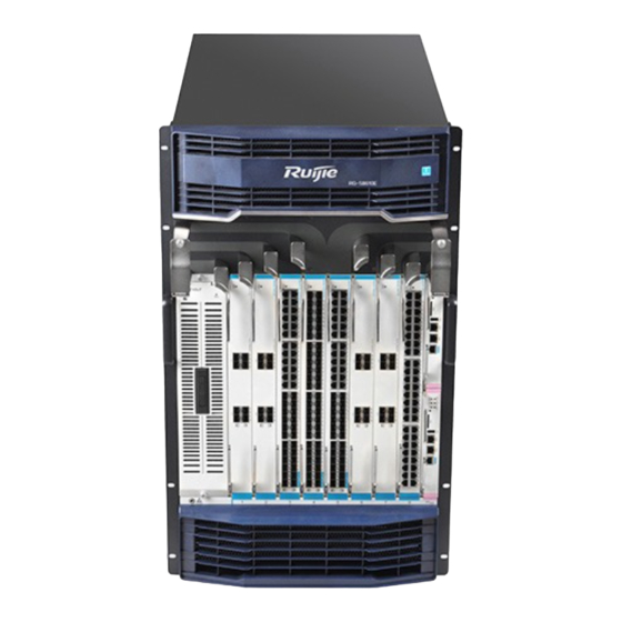
Page 6: Product Appearance
The RG-S8605E switch is an A-class product and may cause radio disturbance to surroundings. In this case, users are advised to take proper measures against the disturbance. Product Appearance The hardware system of the RG-S8605E switch is composed of the chassis, the power system, modules and the cooling system. ... -
Page 7: Front Panel
Front Panel The front panel of the RG-S8605E switch is shown in Figure 1-2. Figure 0-2 Front Panel of the RG-S8605E Switch Note: Cable management bracket Anti-static wrist strap socket Supervisor module slot Service module slot Ensure the supervisor module, service module and power supply module are removed from the chassis before you move or transport the RG-S8605E chassis. -
Page 8: Power Supply
According to the thermal design of the RG-S8605E switch, fans are used to draw air for forced convection cooling in order to ensure that the device works properly in the specified environment. - Page 9 Note: Air intakes for power modules Air intakes for service and supervisor modules Figure 0-5 Ventilation and Heat Dissipation System of the RG-S8605E Switch (Exhaust Vents) Note: Exhaust vents for power modules Exhaust vents for service and supervisor modules For the supervisor and service modules, air flows across the chassis from the right intakes to the left vents.
- Page 10 The chassis should be mounted in a place with sufficient space for air circulation. Sufficient space (10 cm at least) must be reserved at the air intakes and exhaust vents for ventilation. If any module slot is unoccupied, install a filler panel to enable proper airflow. RG-S8607E Specifications Model...
- Page 11 Fan Module M07-FAN EMC Standards GB9254-2008 CLASS A Safety Standards GB4943-2011 Operating 0 to 50°C Temperature Storage -40 to 70°C Temperature Operating Humidity 10%-90% RH (non-condensing) Long term operation altitude: 3000m at 50℃. The temperature decreases by 1℃ as the altitude ranging from 3000m to 4000m increases by each 200m.
- Page 12 Front Panel The front panel of the RG-S8607E switch is shown in Figure 1-7. Figure 0-7 Front Panel of the RG-S8607E Switch Note: Cable management bracket Anti-static wrist strap socket Supervisor module slots Service module slots...
- Page 13 Ensure the supervisor module, service module and power supply module are removed from the chassis before you move or transport the RG-S8607E chassis. Back Panel The back panel of the RG-S8607E switch is shown in the following figure. Figure 0-8 Back Panel of the RG-S8607E Switch Note: ...
- Page 14 The RG-S8607E switches support N+M system power redundancy and 1+1 PoE power redundancy to improve the system stability and reliability. We recommend users to configure redundancy for power supply modules. Heat Dissipation Solution The operating environment temperature of RG-S8607E switches ranges between 0 and 50°C. The heat dissipation design must satisfy the requirement on the device's reliability in the temperature range while ensuring the device's safety and maintainability.
- Page 15 Note: Exhaust vents for power modules Exhaust vents for service and supervisor modules For supervisor and service modules, air flows in from the right intakes and out from the left vents. For the power supply modules, air flows in from the front intakes and out from the back vents. ...
- Page 16 M8600E-48XS-DB M8600E-24XS4QXS-DB M8600E-12QXS-DB M8600E-24SFP/8GT-EB M8600E-24GT/8SFP-EB RG-WALL 1600-B-ED M8600E-08XS-EF M8600E-44SFP4XS-EF M8600E-48GT-EF Hot Swapping Supported Supervisor Module Supported Redundancy RG-PA1600I: 90 to 180 VAC, power: 1200W; 180 to 264 VAC, power: 1600W RG-PA600I: 90 to 180 VAC, power: 600W: 180 to 264 VAC, power: 600W RG-PA1600I-P: 90 to176 VAC, power: 1000W;...
- Page 17 The weight only includes that of the empty chassis and fans. The whole device's weight is subject to that of the modules selected. The RG-S8610E switch is an A-class product and may cause radio disturbance to surroundings. In this case, users are advised to take proper measures against the disturbance.
- Page 18 Front Panel The front panel of the RG-S8610E switch is shown in Figure 1-12. Figure 0-12 Front Panel of the RG-S8610E Switch...
- Page 19 Note: Cable management bracket Handle Supervisor module slots Fan tray of the switch fabric module Service module slots Anti-static wrist strap socket Plastic cover for the air filter of the ⑧ Plastic cover for the power module service module Ensure the supervisor module, service module, switch fabric module and power supply module are removed from the chassis before you move or transport the RG-S8610E chassis.
- Page 20 Note: Power module slots PoE power modules slots Captive screws of the fan tray Fan tray handle Switch fabric modules slots Fans of service module and Grounding point supervisor module ⑧ Anti-static wrist strap socket Power Supply ...
- Page 21 Heat Dissipation Solution The operating environment temperature of RG-S8610E switches ranges between 0 and 50°C. The heat dissipation design must satisfy the requirement on the device's reliability in the temperature range while ensuring the device's safety and maintainability. The supervisor and service modules use fans to draw air and the switch fabric module uses fans to blow air for forced convection in order to ensure that the device works properly in the specified environment.
- Page 22 Note: Exhaust vents for power modules Exhaust vents for service and supervisor modules Exhaust vents for switch fabric modules For supervisor and service modules, air flows in from the front intakes and out from the upper vents. ...
-
Page 23: Module Appearance
The modules of the RG-S8600E switch provide 10/100/1000M auto-sensing Ethernet copper ports, 1000 Mbps/100 Mbps SFP (single-mode/multi-mode) optical fiber interfaces and 10G/40G optical fiber interfaces. M8600E-CM M8600E-CM is the supervisor module of the RG-S8600E series switches and is designed with management and switching functions. -
Page 24: Specifications
Press the button, and the system starts to collect information, during which the device will not restart. After the collection is complete, the device restarts automatically. Hold the button for a while and release it, the device restarts automatically in five seconds. Identification Status Meaning... - Page 25 Hot Swapping Supported Management Supported Redundancy EMC Standards GB9254-2008 CLASS A Safety Standards GB4943-2011 Operating 0 to 50°C Temperature Storage -40 to 70°C Temperature Operating Humidity 10% to 90% RH (non-condensing) MTBF 329,000 hours Weight Net weight: 1.68 kg Dimensions 199 mm x 440 mm x 29.98 mm (W x D x H) The M8600E-CM adopts the CR2032 lithium battery.
- Page 26 Solid green The port is connected at 1000Mbps. Solid yellow The port is connected at 10/100Mbps. Blinking The port is transmitting and receiving data. The port link is NOT connected. Solid green The port is connected at 1000Mbps. SFP port LED Link/ACT Solid yellow The port is connected at 100Mbps.
- Page 27 Humidity MTBF 305,000 hours Weight Net weight: 3.76 kg Dimensions 399 mm x 440 mm x 40.18 mm (W x D x H) M8600E-48GT-ED Module Appearance Figure 0-6 Appearance of the M8600E-48GT-ED Module External Port M8600E-48GT-ED provides 48 copper ports. Copper ports support auto-negotiation at 10/100/1000 Mbps. Copper ports do not support half-duplex at 10/100Mbps.
- Page 28 Storage -40 to 70°C Temperature Operating Humidity 10%-90% RH (non-condensing) MTBF 293,000 hours Weight Net weight: 3.70 kg Dimensions 399 mm x 440 mm x 40.18 mm (W x D x H) M8600E-48GT-EF Module Appearance Figure 0-7 Appearance of the M8600E-48GT-EF Module External Port M8600E-48GT-EF provides 48 copper ports.
- Page 29 Storage -40 to 70°C Temperature Operating Humidity 10%-90% RH (non-condensing) MTBF 290,000 hours Weight Net weight: 3.80 kg Dimensions 399 mm x 440 mm x 40.18 mm (W x D x H) M8600E-48GT-P-ED Module Appearance Figure 0-20 Appearance of the M8600E-48GT-P-ED Module External Port The M8600E-48GT-P-ED provides 48 copper ports.
- Page 30 Model M8600E-48GT-P-ED Quad-core CPU, each core with the clock speed of 1.0G BOOTROM 8 MB Flash Memory 512 MB SDRAM DDRIII 1 GB Port Type 48 copper ports, supporting PoE+ and PoE Transmission Medium 10/100/1000BASE-T Cat-5 UTP Status, Link/ACT, Mode_Led Button Changing switching/PoE mode, and enabling PoE power supply Hot Swapping...
- Page 31 Blinking The port is transmitting and receiving data. The port link is NOT connected. SFP+ port LED Link/ACT Solid green The port is connected. Blinking The port is transmitting and receiving data. Specifications Model M8600E-44SFP4XS-ED Quad-core CPU, each core with the clock speed of 1.0G BOOTROM 8 MB Flash Memory...
- Page 32 It provides 44 SFP ports and four SFP+ ports. The SFP ports support the rate of 100/1000 Mbps, the SFP+ ports support 10G SFP+ modules and Gigabit SFP modules. Hot swapping of the M8600E-44SFP4XS-EF, SFP and SFP+ modules is supported. M8600E-44SFP4XS-EF supports 10G SFP+ and Gigabit SFP modules.
- Page 33 Operating 0 to 50°C Temperature Storage -40 to 70°C Temperature Operating 10%-90% RH (non-condensing) Humidity MTBF 299,000 hours Weight Net weight: 3.86 kg Dimensions 399 mm x 440 mm x 40.18 mm (W x D x H) M8600E-08XS-ED Module Appearance Figure 0-23 Appearance of the M8600E-08XS-ED Module External Port It provides eight SFP+ ports.
- Page 34 10GBASE-SR (850nm) Multi-mode optical fiber 10GBASE-LR (1310nm) Single-mode optical fiber 10GBASE-ER (1550nm) Single-mode optical fiber 10GBASE-ZR (1550nm) Single-mode optical fiber XG-SFP-CU1M 1m SFP+ copper cables (DAC) XG-SFP-CU3M 3m SFP+ copper cables (DAC) XG-SFP-CU5M 5m SFP+ copper cables (DAC) Status, Link/ACT Hot Swapping Supported Power Consumption...
- Page 35 Model M8600E-08XS-EF Quad-core CPU, each core with the clock speed of 1.0G BOOTROM 8 MB Flash Memory 512 MB SDRAM DDRIII 2 GB Port Type Eight SFP+ ports supporting 10G SFP+ modules and 1G SFP modules 1000BASE-SX (850nm) Multi-mode optical fiber 1000BASE-LX (1310nm) Single-mode optical fiber 1000BASE-LH (1310nm)
- Page 36 indicates errors. Solid green The module is operational System temperature exceeds the alarm Solid yellow temperature. The system keeps operating but the performance is affected. The port link is NOT connected. SFP+ port LED Link/ACT Solid green The port is connected. Blinking The port is transmitting and receiving data.
- Page 37 Identification on Status Meaning the panel The module is NOT receiving power. Solid red The module is faulty. Initialization is in progress. Continuous blinking Blinking green indicates errors. System LED Status Solid green The module is operational System temperature exceeds the alarm Solid yellow temperature.
- Page 38 The M8600E-24XS4QXS-DB supports 10G SFP+ and Gigabit SFP modules. 10G SFP+ modules cannot be used as Gigabit SFP modules. Identification on Status Meaning the panel The module is NOT receiving power. Solid red The module is faulty. Initialization is in progress. Continuous blinking Blinking green indicates errors.
- Page 39 Operating Humidity 10%-90% RH (non-condensing) MTBF 316,000 hours Weight Net weight: 4.0 kg Dimensions 399 mm x 440 mm x 40.18 mm (W x D x H) M8600E-24GT/8SFP-EB Module Appearance Figure 0-28 Appearance of the M8600E-24GT/8SFP-EB Module External Port M8600E-24GT/8SFP-EB provides 24 10/100/1000BASE-T RJ45 ports, eight SFP ports. The last eight copper ports are copper/fiber combo ports.
- Page 40 Quad-core CPU, each core with the clock speed of 1.0G BOOTROM 8 MB Flash Memory 512 MB SDRAM DDRIII 1 GB 24 10/100/1000BASE-T RJ-45 ports, eight SFP ports. The last eight copper ports are copper/fiber Port Type combo ports. 10/100/1000BASE-T Cat-5 UTP 100BASE-FX(1310nm) Multi-mode or single-mode optical fiber...
- Page 41 Identification on Status Meaning the panel The module is NOT receiving power. Solid red The module is faulty. Initialization is in progress. Continuous blinking Blinking green indicates errors. System LED Status Solid green The module is operational. System temperature exceeds the alarm Solid yellow temperature, affecting system performance.
- Page 42 MTBF 403,000 hours Weight Net weight: 3.2 kg Dimensions 399 mm x 440 mm x 40.18 mm (W x D x H) RG-WALL 1600-B-ED Module Appearance Figure 0-30 Appearance of the RG-WALL1600-B-ED Module External Port It provides two SFP+ ports. The SFP+ ports support 10G SFP+ modules and Gigabit SFP modules. Hot swapping of the RG-WALL1600-B-ED, SFP and SFP+ modules is supported.
- Page 43 10GBASE-ER (1550nm) Single-mode optical fiber 10GBASE-ZR (1550nm) Single-mode optical fiber XG-SFP-CU1M 1m SFP+ copper cables (DAC) XG-SFP-CU3M 3m SFP+ copper cables (DAC) XG-SFP-CU5M 5m SFP+ copper cables (DAC) Status, Link/ACT Hot Swapping Supported Power Consumption <190W EMC Standards GB9254-2008 CLASS A Safety Standards GB4943-2011 Operating...
- Page 44 Figure 0-32 Appearance of the RG-PA1600I Module External port The RG-PA1600I module provides 12 VAC input to the overall system of the RG-S8605E/RG-S8607E/RG-S8610E switch. The front panel of the power supply module provides a 3-pin power port, which can be connected to standard 16A power cord.
- Page 45 Figure 0-33 Appearance of the RG-PA600I Module External Port The RG-PA600I module provides 12 VAC input to the overall system of the RG-S8605E/RG-S8607E/RG-S8610E switch. The front panel of the power supply module provides a 3-pin power port, which can be connected to standard 10A power...
- Page 46 Meaning DC/FLT Solid green Solid green The module is operational Solid red There is no power input or input undervoltage. Solid green Solid red Overvoltage Solid green Solid red Overcurrent Solid green Solid orange Temperature alarm Solid green Solid red Over-temperature fault Solid green Solid red...
- Page 47 Do not connect the PoE power cord to the system power supply. The 3-pin power port for the PoE module is on the switch. RG-S8605E switch provides one PoE power module slot and one 3-pin power port. RG-S8607E switch provides two PoE power module slots (PoE1 and PoE2) and two 3-pin power ports (port for PoE1 is the left one of ...
- Page 48 Alarm Fault Solid green The module is operational There is no power input Blinking green The module is in standby mode Solid green Solid yellow Persistent overcurrent. Solid green Solid yellow Temperature alarm Solid red Over-temperature causes power-off Solid red AC is powered off.
- Page 49 As an AC power module, the RG-PA1600I-PL module provides PoE power input to the overall system of the RG-S8605E/RG-S8607E/RG-S8610E switch. External Port The 3-pin power port for the PoE module is on the switch. This port can be connected to standard 16 A power cord.
- Page 50 Do not connect the PoE power cord to the system power supply. The 3-pin power port for the PoE module is on the switch. RG-S8605E switch provides one PoE power module slot and one 3-pin power port. RG-S8607E switch provides two PoE power module slots (PoE1 and PoE2) and two 3-pin power ports (port for PoE1 is the left one of ...
- Page 51 Figure 0-38 Appearance of the RG-PA3000I-PL Module As an AC power module, the RG-PA 3000I-PL module provides PoE power input to the overall system of the RG-S8605E/RG-S8607E/RG-S8610E. External Port The 3-pin power port for the PoE module is on the switch. This port can be connected to standard 16 A power cord.
- Page 52 Do not connect the PoE power cord to the system power supply. The 3-pin power port for the PoE module is on the switch. RG-S8605E switch provides one PoE power module slot and one 3-pin power port. RG-S8607E switch provides two PoE power module slots (PoE1 and PoE2) and two 3-pin power ports (port for PoE1 is the left one of ...
- Page 53 When you plug in the power cord, please fasten the anti-loose buckle to the power cord to prevent loosening. Operation altitude: 5000m max. Storage altitude: 5000m max. RG-PD1600I Module Appearance Figure 0-40 Appearance of the RG-PD1600I Module External port The RG-PD1600I module provides one DC (-48 V) power port. Meaning Solid green Solid green...
- Page 54 Solid green Solid red Fan failure Specifications Module Model RG-PD1600I Rated Voltage -48 VDC Range Max Voltage -40 to -75 VDC Range Max Power 1400 W Output Weight Net weight: 1.60 kg Power Cord 50A power cord Requirement Please connect the power cord to the corresponding terminal according to the color and then tighten the screws.
- Page 55 Meaning Solid green Solid green The module is operational There is external power supply. The power module is not in Solid green Solid red use. There is no external power supply. The power module is in Solid red use. Solid red Overcurrent Solid green Solid red...
- Page 56 Composition The M05-FAN is the fan for service modules and supervisor modules on the RG-S8605E. An M05-FAN is composed of eight 80 mm x 80 mm x 38 mm fans and one fan control board. The M05-FAN draws air out to form convection for heat dissipation.
- Page 57 M07-FAN Module Appearance Figure 0-43 Appearance of the M07-FAN Module Note: Protective cover for fans Captive screws of the fan tray Fan status LED ④ Fan handle Composition The M07-FAN is the fan for service modules and supervisor modules on the RG-S8607E. One M07-FAN is composed of eight 80 mm x 80 mm x 38 mm fans and one fan control board.
- Page 58 Solid green The fan is operational. Features Function Meaning Status Monitoring Rotational speed monitoring, failure alarm Automatic Speed-adjustment controlled by temperature Speed-adjustment Hot Swapping Hot swapping is supported by the fan tray. M10-FAN-R Module Appearance Figure 0-44 Appearance of the M10-FAN-R Module ...
- Page 59 Dimension 245.8 mm x 177 mm x 144.2 mm (W x D x H) Status Meaning The fan is NOT receiving power or fails. Status Solid green The fan is operational. Features Function Meaning Status monitoring Rotational speed monitoring, failure alarm Automatic Speed-adjustment controlled by temperature Speed-adjustment...
- Page 60 Note: Fan status LED Fan handle Captive screws of the fan tray Composition The M10-FAN-F is the fan for switch fabric modules on the RG-S8610E. There are one M10-FAN-R trays with six 80 mm x 80 mm x 38 mm fans and one fan control board. The M10-FAN-F draws air out to form convection for heat dissipation. Specifications Fan Model M10-FAN-F...
-
Page 61: Preparation Before Installation
Preparation before Installation Safety Suggestions To avoid body injury and equipment damage, please carefully read the safety suggestions before you install RG-S8600E. The following safety suggestions do not cover all possible dangers. General Suggestions Take security measures (such as wearing an anti-static wrist strap) to ensure safety. Keep the chassis clean, free from any dust. -
Page 62: Static Discharge Damage Prevention
For safety, use a multimeter to measure the resistance between yourself and the ground, which should be within the range from 1 to 10 Ω. Make sure that the switch is properly grounded when the anti-static wrist strap is connected to the ground through the chassis jack. Figure 0-1 Preventing EMI on RG-S8605E... - Page 63 Figure 2-2 Preventing EMI on RG-S8607E Figure 2-3 Preventing EMI on RG-S8610E...
-
Page 64: Laser Safety
Laser Safety Among the modules supported by RG-S8600E, there are a great number of optical modules that are Class I laser products. Precautions: When a fiber transceiver works, ensure that the port has been connected with a fiber or is covered with a dust cap so as to keep out dust and avoid burning your eyes. -
Page 65: Space Requirements
Ventilation Requirements See RG-S8605E, RG-S8607E and RG-S8610E in Product Overview for their heat dissipation and ventilation respectively. Sufficient space (10 cm at least) must be reserved at the air intakes and exhaust vents for ventilation. After connecting various cables, you should bundle the cables or place them in the cable management bracket to avoid blocking air intakes. -
Page 66: Cleanness Requirements
Dust particles (diameter ≥5μm) ≤3×10 The air filter of the RG-S8605E/RG-S8607E/RG-S8610E must be cleaned at interval to ensure good ventilation and dust prevention. Apart from dust, the salt, acid and sulfide in the air in the equipment room must also meet strict requirements; as such poisonous substances may accelerate the corrosion of the metal and the aging of some parts. -
Page 67: System Grounding Requirements
Input power shall be larger than the actual power consumption of entire system. For example, the RG-S8610E chassis is installed with two M8600E-CM , two M8600E-48XS-DB and two M8610E-FE-D I modules, the total power consumption of the device would be: 2 x 44W (M8600E-CM)+ 2 x 232W (M8600E-48XS-DB) + 3 x174W (M10-FAN-R) + 219W (M10-FAN-F) +2 x 10⁷W (M8610E-FE-D I) = 1507W. -
Page 68: Cabinet Mounting
The building installation shall provide a means for connection to protective earth, and the equipment is to be connected to that means. Lightning Grounding The lightning protection system of the facility is a separate system that consists of the lightning rod, down lead conductor and the connector to the grounding system, which usually shares the power reference ground and yellow/green safety cable ground. - Page 69 Be sure that the square hold strip is at least 180 mm far from the outboard front door and the door is at most 25 mm thick to ensure a minimum available distance of 155 mm. The front door is at least 1000 mm far from the back door, Figure 2-5 Cabinet Dimensions ...
-
Page 70: Installation Tools
Be sure that the front and back doors of the cabinet have porosities greater than 50% for good ventilation and heat dissipation. Installation Tools Cross screwdriver, straight screwdriver, related electric and optical cables Bolts, diagonal pliers, straps Common Tools Anti-static glove, stripping pliers, crimping pliers, crimping pliers for the crystal head, Special Tools wire cutter... -
Page 71: Product Installation
Product Installation RG-S8600E series Ethernet switch must be used and fixed in the room. Make sure you have carefully read part 2 and this part, and be sure that the requirements set forth in part 2 have been met. Installation Procedure Installation Verification The RG-S8600E is complicated equipment, so you must carefully plan and arrange the installation location, networking mode, power supply, and wiring before installation. -
Page 72: Installing The Air Filter (Optional)
Insert the air filter along the slide rail. Note the direction identifier to ensure the correct direction. Use a screwdriver to tighten the captive screws on the air filter. Figure 3-2 Installing the Air Filter of the Supervisor Module and Service Module on the RG-S8605E Switch... - Page 73 (2) RG-S8607E Figure 3-3 Air Filter of the Supervisor Module and Service Module on RG-S8607E Switch Note: Captive screws Air filter To install the air filter , follow these steps: Insert the air filter along the slide rail. Note the direction identifier to ensure the correct direction. Use a screwdriver to tighten the captive screws on the air filter.
- Page 74 (3) RG-S8610E To install the air filter , follow these steps: Seat the air filter in the plastic cover and tighten screws. Install the plastic cover before the air filter by pressing firmly the two buttons on the both sides of the plastic cover. Figure 3-5 Installing the Air Filter of the Supervisor Module and Service Module on RG-S8610E Switch...
-
Page 75: Installing Brackets
Wear the antistatic wrist strap and make sure the antistatic wrist strap is grounded well. The brackets of RG-S8605E, RG-S8607E and RG-S8610E are installed before delivery, as shown in figure 3-7, 3-8 and 3-9). If you want to adjust the location of the bracket, see figure 3-10, 3-11 and 3-12. - Page 76 (2) RG-S8607E bracket (installed before delivery) Figure 3-8 Installing Brackets to Front Chassis Side (3) RG-S8610E bracket (installed before delivery) Figure 3-9 Installing Bracket to Front Chassis Side...
- Page 77 Move the bracket backward (1) RG-S8605E bracket Remove the bracket from the front chassis side. Install the bracket at a backward location, as shown in figure 3-10: Figure 3-10 RG-S8605E Bracket...
- Page 78 (2) RG-S8607E bracket Remove the bracket from the front chassis side. Install the bracket at a backward location, as shown in figure 3-11: Figure 3-11 RG-S8607E Bracket (3) RG-S8610E bracket Remove the bracket from the front chassis side. Install the bracket at a backward location, as shown in figure 3-12:...
-
Page 79: Mounting Cable Management Brackets
Mounting Cable Management Brackets Make sure the antistatic wrist strap is grounded well and wear the antistatic wrist strap. The RG-S8610E cable management bracket is mounted before delivery while RG-S8605E and RG-S8607E not. Please refer to the following steps and figures for installation. - Page 80 Align the screw holes on the cable management bracket with those on the chassis and tighten the screws, as shown in figure 3-13. Figure 3-13 Mounting the Cable Management Bracket for RG-S8605E Mount the cable management bracket for RG-S8607E Take out cable management brackets.
-
Page 81: Mounting The Cabinet
Mount the cable management bracket for RG-S8610E (mounted before delivery) Figure 3-15 Mounting the Cable Management Bracket for RG-S8610E Mounting the Cabinet Precautions When you install the cabinet, pay attention to the following: All expansion bolts for fastening the cabinet base to the ground should be installed and tightened in sequence from bottom up (large plain washer, spring washer, and nut), and the installation holes on the base and the expansion bolts should be well aligned. -
Page 82: Installation Steps
After the cabinet is installed, it should be vertical to the ground. When multiple cabinets are put side by side in the room, they should be aligned in a straight line, with an error less than 5 mm. ... -
Page 83: Mounting The Switch To A Cabinet
The RG-S8600E series switch is available in three models with different heights. There are variable kinds of slide rails. The rail appearance and installation is subject to actual conditions. In order to keep the cabinet balanced, please install the slide rail to as low a position as possible in the cabinet if only one RG-S8600E switch is installed. - Page 84 Place the switch on the slide rail, and drive it smoothly into the cabinet until the front bracket reaches the square hole strip. Align the installation holes on the bracket with the cage nuts on the square hole strip, and mount them with screws. Figure 3-18 Mounting the Switch into the Cabinet...
-
Page 85: Connecting The System Ground
Attach the one end of the grounding wire to the switch with the two screws. Connect the other end of the grounding wire to the grounding wire of the cabinet. Figure 3-19 Grounding Point on the Rear of the RG-S8605E Switch Figure 3-20 Grounding Point on the Rear of the... - Page 86 Figure 3-21 Grounding Point on the Rear of the RG-S8610E Switch...
-
Page 87: Installing Power Supplies
It is recommended users configure power supply redundancy. When RG-S8605E/ RG-S8607E/ RG-S8610E is powered up by more than one source, the power must be in the same model. If you want to carry or lift the power module, please hold the bottom of the module with your hand instead of... - Page 88 Before inserting or removing the power module, please verify whether the switch is well mounted. The switch is high, avoid switch tumble when you are inserting or removing the power module. If you want to hot swap a power supply, please make sure that the interval between two operation is greater than 30 seconds.
-
Page 89: Installing Fans
Steps for installing the M05-FAN fan tray: Install the fan tray into the fan slot in the rear panel of RG-S8605E. Note the direction identifier of the fan tray’s name to ensure the correct direction. Tighten the captive screws on the fan tray with a screwdriver. - Page 90 Steps for installing the M10-FAN-R fan tray: Install the fan tray into the fan slot in the rear panel of RG-S8610E. Note the direction identifier of the fan tray’s name to ensure the correct direction. Tighten the captive screws on the fan tray with a screwdriver. Figure 3-25 Installing M10-FAN-R Fan Tray...
-
Page 91: Installing Modules
Steps for installing the M10-FAN-F fan tray: Install the fan tray into the fan slot in the front panel of RG-S8610E. Note the direction identifier of the fan tray’s name to ensure the correct direction. Tighten the captive screws on the fan tray with a screwdriver. Figure 3-26 Installing M10-FAN-F Fan Tray Do not remove the fan tray forcibly. - Page 92 Hold down the button on the lever (refer to 1 in figure 3-27) and then pull out the lever (refer to 2 in figure 3-27). Figure 3-27 Pulling out the Lever Figure 3-28 Pulling out the Levers with Both Hands Select slots (RG-S8605E) Figure 3-29 RG-S8605E Chassis...
- Page 93 Note: ①Supervisor module slot ②Service module slot Select slots (RG-S8607E) Figure 3-30 RG-S8607E Chassis Note: ①Supervisor module slot ②Service module slot Select slots (RG-S8610E) Figure 3-31 RG-S8610E Chassis Note: ① Service module slot ② Supervisor module slot ③ Switch fabric module slot...
- Page 94 Install modules For the installation of the supervisor module, service module and switch fabric module, please refer to figure 3-32, 3-33 and 3-34. Install modules into slots (RG-S8605E) Pull out both levers (refer to ① in figure 3-32). Insert the module into the slot along the rail and drive it ahead smoothly (refer to ②...
-
Page 95: Installing Swappable Interface Modules (Optional)
If any module slot is unoccupied, install a filler panel to enable proper airflow and heat dissipation. Installing Swappable Interface Modules (Optional) Make sure the optical modules connected to both ends of a fiber are the same type while replacing swappable optical modules. -
Page 96: Installing Sfp+/Sfp Modules
Installing SFP+/SFP Modules To avoid damaging components due to operation errors, read this section carefully before installing SFP+/SFP modules. To install the SFP/SFP+ module, do as follows: Turn up the handle of the module into the top bail-clasp latch. Hold both sides of the module and push the module into place (You can feel that the module is placed in position with a click sound). -
Page 97: Installing 40-Gigabit Qsfp+ Modules
After you connect the copper module to the Ethernet network through the connector, the Link/ACT status is on. Otherwise, please check the connector. Precaution If the SFP+ copper module cannot be inserted to the end, do not push it forcefully. Please try the other end of the module. -
Page 98: Installing 40-Gigabit Qsfp+ Cables
Figure 3-40 Installing the QSFP+ Module Equipped with a Pull Tap Use the fiber optical patch cord to connect the 40G QSFP+ module to the fiber optical network. Select the patch cord with the connector corresponding to the port. After the patch cord is connected, the Link/ACT Status LED is on. Otherwise, please check connection of the patch cord. -
Page 99: Connecting The Power Cord
After the cable is connected, the Link/ACT Status LED is on. Otherwise, please check the connector. Precaution If the QSFP+ copper module cannot be inserted to hit the back panel, do not push it forcefully. Please try the other end of the module. - Page 100 Figure 3-43 Connecting the Power Cord Please use the 3-pin power cord. The cross-sectional area of each pin is 1.5 mm or 14 AWG minimum. 16A and 10A power cords are available for the RG-S8605E, RG-S8607E and RG-S8610E AC power supply.
- Page 101 Before connecting the power supply, make sure the external power supply matches the power module inside the unit. Before connecting the DC power cord to the terminal, make sure the other end of power cord is not plugged Make sure the power supply is properly connected. Installation Verification ...
- Page 102 Verify that the power cord is long enough to avoid being stretched. Verify that the rated current of the external power socket is greater 16A and that the socket is grounded well. Verify that each power module is connected to a power socket. ...
-
Page 103: Establishing The Configuration Environment
System Debugging Establishing the Configuration Environment Establishing the Configuration Environment If you log in to the switch for the first time, please use the Console port. Connecting the Console Cable Connect one end of the DB-9 jack of the console cable to the serial port of the PC. Connect one end of the console cable RJ45 to the Console port of the switch. -
Page 104: Setting Terminal Parameters
Setting Terminal Parameters Start the PC and run the terminal simulation program on the PC, such as Terminal on Windows 3.1 or HyperTerminal on Windows 95/98/NT/2000/XP. Set terminal parameters. The parameters are as follows: baud rate 9600, data bit 8, parity check none, stop bit 1, and flow control as none. -
Page 105: Power-On Startup
After setting the serial port parameters, click OK. The Hyperterminal window appears.. Power-on Startup Checking Before Power-on The switch is fully grounded. The power cable is correctly connected. The power supply voltage complies with the requirement of the switch. ... -
Page 106: Monitoring And Maintenance
Monitoring and Maintenance Monitoring Indicators When the RG-S8600E is running, you can monitor the status of each module by inspecting the status LED of the appropriate module. When the Alarm LED of the master supervisor module is red, it means the system has a fault, in which case you can log in to the management software to perform troubleshooting. -
Page 107: Power Supply Maintenance
Replacing Fuses To replace the old fuse wire with the correspondent new one, please contact the technical support representatives of Ruijie Networks. The following table lists the specifications for the module fuses. Module Fuse Slot Number Fuse Specification... -
Page 108: General Installation Troubleshooting Flow
Check the connection of the fibers or cables of various ports Contact Technical Support of Ruijie Networks for hardware Common Troubleshooting Procedures Fault 1: The AC power module does not work. Fault Description: The Status LED of each service module is OFF, the Power LED of the fan tray is OFF, and the fan does not work. - Page 109 Troubleshooting: First place the switches of all the power modules to OFF. Check if the cables of the cabinet have been correctly connected. Check whether the power cables are tightly connected to the cabinet power sockets and power modules. Check whether the power modules are installed correctly.
- Page 110 Check whether the rates of the two sides match and whether the optical fiber type meets requirements. In addition, for ports supporting different rates, check whether rate modes are configured correctly. If above mentioned methods do not take effect, please contact Ruijie Networks for technology assistance.
-
Page 111: Replacing Modules
Loosen the captive screws on the air filter. Remove the air filter. Figure 7-1 Installing and Removing the Air Filter of the RG-S8605E Supervisor and Service Modules Note: A: Air filter to be removed B: Air filter to be installed ... -
Page 112: Removing, Cleaning And Installing Air Filter For Switch Fabric Module
Note: A: Air filter to be removed B: Air filter to be installed Remove and Install the air filter of the RG-S8610E supervisor and service modules Hold down the buttons on both sides of the plastic cover and remove the plastic cover. Loosen the screws on the air filter. -
Page 113: Removing Swappable Interface Modules (Optional)
Figure 7-4 Installing and Removing the Air Filter of the RG-S8610E Switch Fabric Module Removing Swappable Interface Modules (Optional) Removing SFP+/SFP Modules Take the following steps to remove SFP/SFP+ modules: Unplug the optical fiber. Turn down the handle of the module until it is horizontal. Pull the tap to take out the SFP/SFP+ module, as shown in figure 7-5. -
Page 114: Removing 40-Gigabit Qsfp+ Modules
Precaution Pull the tap out before unplugging the cables. Otherwise, the module or the slot can be damaged. Immediately install the dust plug to the module port and the switch fiber port. Removing 40-Gigabit QSFP+ Modules Unplug the optical fiber. If you want to remove the module equipped with a bail-clasp latch, turn down the handle of the module until it is horizontal and pull the bail-clasp latch to take out the QSFP+ module, as shown in figure 7-7. - Page 115 Drive the levers close to the module, and the module will hit the back panel. The module will be fastened after self-locking of levers. Figure 7-10 Replacing the Module (for RG-S8605E) Figure 7-11 Replacing the Module (for RG-S8607E)
- Page 116 Figure 7-12 Replacing the Module (for RG-S8610E)
-
Page 117: Removing Power Modules
In order to ensure the reliability of the system ventilation and heat dissipation performance and address the requirement of the dust-filter, filler panel needs to be installed in the slot where no supervisor module or service module has been installed. If you want to remove the module when the device is electrified, you need to insert the new module or install the filler panel within 10 minutes. -
Page 118: Removing Fans
Pull out the fan tray and put it in the anti-static bag. Insert the fan tray into the slot along the slide rail until the fan tray hits the back panel. Tighten the captive screws on the fan tray with the Phillips screwdriver. Figure 7-14 Replacing the Fan for RG-S8605E... - Page 119 Note: A: Fan modules to be removed B: Fan modules to be installed Figure 7-15 Replacing the Fan for RG-S8607E Note: A: Fan modules to be removed B: Fan modules to be installed Figure 7-16 Replacing the Fan for RG-S8610E Supervisor and Service Modules Note: A: Fan modules to be removed B: Fan modules to be installed...
- Page 120 Note: A: Fan modules to be removed B: Fan modules to be installed...
-
Page 121: Connecting The External Port Cables
Cables This chapter describes the precautions and simple steps for cable connection and bundling. See Appendix D cabling Recommendations in Installation for detailed cabling and bundling. Connecting the External Port Cables Precautions Correctly distinguish single-mode and multi-mode fibers and ports. ... -
Page 122: Appendix A Connectors And Media
Appendix A Connectors and Media 1000BASE-T/100BASE-TX/10BASE-T The 1000BASE-T/100BASE-TX/10BASE-T is a 10/100/1000 Mbps auto-negotiation port that supports auto MDI/MDIX. Compliant with IEEE 802.3ab, 1000BASE-T requires Category 5e 100-ohm UTP or STP (STP is recommended) with a maximum distance of 100 meters (328 feet). 1000BASE-T requires all four pairs of wires be connected for data transmission, as shown in Figure A-1 Figure A-1 1000BASE-T Connection 10BASE-T uses Category 3, 4, 5 100-ohm UTP/STP and 1000BASE-T uses Category 5 100-ohm UTP/STP for... -
Page 123: Fiber Connection
Fiber Connection You can choose to use single mode or multimode fibers according to the transceiver module types. Figure A-4 shows connection of fiber cables. Figure A-4 Fiber Connection... -
Page 124: Appendix B Mini-Gbic, 10-Gigabit Sfp+ And 40-Gigabit Qsfp+ Modules Specifications
Appendix B Mini-GBIC, 10-Gigabit SFP+ and 40-Gigabit QSFP+ Modules Specifications Ruijie provides various Gigabit SFP (Mini-GBIC modules), 10-Gigabit SFP+ and 40-Gigabit QSFP+ transceivers for interfaces of modules on the switch. You can select the most suitable SFP, SFP+ or QSFP+ transceivers as needed. This appendix describes the models and specifications of some of the Gigabit SFP, 10-Gigabit and 40-Gigabit QSFP+ transceivers for your reference. - Page 125 (dBm) 62.5 XG-SFP-SR-MM850 -7.5 2000 300m connector) XG-SFP-LR-SM1310 1310 10km -8.2 -10.3 connector) XG-SFP-ER-SM1550 1550 40km -4.7 -11.3 connector) Table B-4 Existing 10-Gigabit SFP+ Copper Cable Models Support Module Conductor Model Connector Length(m) Data Rate(Gb/s) Type diameter(AWG) (Yes/No) XG-SFP-CU1M Passive SFP+ 10.3125 XG-SFP-CU3M...
-
Page 126: Appendix C Switch Lightning Protection
Appendix C Switch Lightning Protection Installing AC Power Arrester (lightning protection cable row) The external lightning protection cable row shall be used on the AC power port to prevent the switch from being struck by lightning when the AC power cable is introduced from the outdoor and directly connected to the power port of the switch. The lightning protection cable row is fixed on the cabinet, operating table or the wall in the machine room using the line buttons and screws. - Page 127 Tear one side of the protection paper for the double-sided adhesive tape and paste the tape to the framework of the Ethernet port arrester. Tear the other side of the protection paper for the double-sided adhesive tape and paste the Ethernet port arrester to the switch framework.
-
Page 128: Appendix D Cabling Recommendations In Installation
Appendix D Cabling Recommendations in Installation When RG-S8600E series switches are installed in standard 19-inch cabinets, route cable bundles upward or downward along the sides of the rack depending on the actual situation in the equipment room. All cable connectors should be placed at the bottom of the cabinet rather than be exposed outside of the cabinet. - Page 129 If cables are to be bent, bind them first but do not tie cable ties within the bend to avoid stress on the cables, which may otherwise cause the wires inside to break, as shown in Figure D-3. Figure D-3 Do Not Tie Cable Ties within the Bend ...
- Page 130 Flat washer Spring washer Note Flat washer When using a stiff cable, fix it near the cable lug to avoid stress on the lug and cable. Do not use self-tapping screws to fasten terminals. Bundle cables of the same type and running in the same direction into groups. Keep cables clean and straight. ...
-
Page 131: Appendix E Site Selection
Appendix E Site Selection The machine room should be at least 5km away from the heavy pollution source such as the smelter, coal mine and thermal power plant, 3.7km away from the medium pollution source such as the chemical industry, rubber industry and electroplating industry, and 2km away from the light pollution source such as the food manufacturer and leather plant.
Need help?
Do you have a question about the RG-S8605E and is the answer not in the manual?
Questions and answers