Table of Contents
Advertisement
Quick Links
Advertisement
Table of Contents

Related Manuals for Invertek Drives Optidrive Plus 3GV


Summary of Contents for Invertek Drives Optidrive Plus 3GV
- Page 1 Optidrive Plus 3 AC Variable Speed Drive 0.37 – 160kW (0.5 – 250HP) ...
- Page 2 Declaration of Conformity: Invertek Drives Ltd hereby states that the Optidrive Plus 3 product range is CE marked for the low voltage directive and conforms to the following harmonised European directives: EN 61800‐5‐1: 2003 Adjustable speed electrical power drive systems. Safety requirements. Electrical, thermal and energy. EN 61800‐3 2 Ed: 2004 Adjustable speed electrical power drive systems. EMC requirements and specific test methods EN 55011: 2007 Limits and Methods of measurement of radio disturbance characteristics of industrial, scientific and medical (ISM) radio‐frequency equipment (EMC) EN60529 : 1992 Specifications for degrees of protection provided by enclosures CE ‐ Konformitätserklärung: gemäß den Produktnormen für Drehzahlveränderbare Antriebe, die Firma ‘Invertek Drives Ltd., UK erklärt dass das Produkt: Optidrive Plus/VTC (statischer Frequenzumrichter zur Drehzahlregelung von Asynchronmotoren) nach den folgenden harmonisierten Produktnormen entwickelt und gebaut wird: EN 61800‐5‐1: 2003 Elektrische Leistungsantriebessysteme mit einstellbarer Drehzahl. Anforderungen an die Sicherheit. Elektrische, thermische und energetische Anforderungen EN 61800‐3 2 Ed: 2004 Drehzahlveraenderbare elektrische Antriebe. EMV‐Anforderungen einschliesslich spezieller Prueverfahren EN 55011: 2007 Industrielle, wissenschaftliche und medizinische Hockfrequenzgeraeten (ISM‐Geraeten). Funkstoerungen. Grenzwerte und Messverfahren EN60529 : 1992 Schutzarten durch Gehaeuse (IP Code) Déclaration de Conformité: Invertek Drives Ltd déclare par la présente que le produit Optidrive Plus/VTC porte le marquage CE en relation avec la directive basse tension et est conforme aux normes Européennes harmonisées suivantes : EN 61800‐5‐1: 2003 Entrainements électriques de puissance à vitesse variable. Exigences de sécurité. Electrique, thermique et énergétique ...
-
Page 3: Table Of Contents
1. INTRODUCTION ..............................4 1.1. Important safety information ...................... 4 1.2. Electromagnetic Compatibility (EMC)..................4 2. GENERAL INFORMATION AND RATINGS......................5 2.1. Drive model numbers ........................5 3. MECHANICAL INSTALLATION ..........................6 3.1. Mechanical dimensions and mounting ..................6 3.2. General............................8 ... -
Page 4: Introduction
1. Introduction 1.1. Important safety information This variable speed drive product (Optidrive) is intended for professional incorporation into complete equipment or systems. If installed incorrectly it may present a safety hazard. The Optidrive uses high voltages and currents, carries a high level of stored electrical energy, and is used to control mechanical plant that may cause injury. Close attention is required to system design and electrical installation to avoid hazards in either normal operation or in the event of equipment malfunction. System design, installation, commissioning and maintenance must be carried out only by personnel who have the necessary training and experience. They must carefully read this safety information and the instructions in this Guide and follow all information regarding transport, storage, installation and use of the Optidrive, including the specified environmental limitations. Please read the IMPORTANT SAFETY INFORMATION below, and all Warning and Caution information elsewhere. Indicates a potentially hazardous situation which, if not Indicates a potentially hazardous situation which, if not avoided, could result in injury or death. avoided, could result in damage to property. Safety of machinery, and safety‐critical applications The level of integrity offered by the Optidrive control functions – for example stop/start, forward/reverse and maximum speed, is not sufficient for use in safety‐critical applications without independent channels of protection. All applications where malfunction could cause injury or loss of life must be subject to a risk assessment and further protection provided where needed. Within the European Union, all machinery in which this product is used must comply with Directive 89/392/EEC, Safety of Machinery. In particular, the electrical equipment should comply with EN60204‐ 1. Optidrives should be installed only by qualified electrical persons and in accordance with local and national regulations and codes of practice. The Optidrive has an Ingress Protection rating of IP20. For higher IP ratings, use a suitable enclosure. Electric shock hazard! Disconnect and ISOLATE the Optidrive before attempting any work on it. High voltages are present at the terminals and within the drive for up to 10 minutes after disconnection of the electrical supply. Where supply to the drive is through a plug and socket connector, do not disconnect until 10 minutes have elapsed after turning off the supply. Ensure correct earthing connections. The earth cable must be sufficient to carry the maximum supply fault current which normally will be limited by the fuses or MCB The STOP function does not remove potentially lethal high voltages. ISOLATE the drive and wait 10 minutes before commencing any work. Parameter P1‐01 can be set to operate the motor at up to 120,000 rpm, hence use this parameter with care. If it is desired to operate the drive at any frequency/speed above the rated speed (P1‐09/ P1‐10) of the motor, consult the manufacturers of the motor and the driven machine about suitability for over‐speed operation. ... -
Page 5: General Information And Ratings
2. General Information and Ratings 2.1. Drive model numbers 200‐240V ±10% ‐ 1 Phase Input 480‐525V ±10% ‐ 3 Phase Input (Note : Not UL Approved) Output Output kW Model HP Model Frame kW Model HP Model Frame kW HP Current kW HP Current Number Number Size Number Number Size (A) (A) ODP‐12037‐xx 0.37 ODP‐12005‐USA 0.5 2.3 1 ODP‐55550‐xx 55 N/A ... -
Page 6: Mechanical Installation
3. Mechanical Installation 3.1. Mechanical dimensions and mounting 3.1.1. Frame Size 1 Overall Dimensions Height 155mm Width 80mm Depth 130mm A 105mm B 72mm Incoming Power Terminals C 25mm Help Card Footprint View Keypad & Display – See Section 4.8 on page 11 RJ11 Connector – See Section 10.3 on page 31 Weight : 1.1Kg Infra Red Interface Control Terminals – See Section 4.7 on page 11 Motor Connection Terminals ... - Page 7 3.1.4. Frame Size 4 Overall Dimensions Height 520mm Width 340mm Depth 220mm A 420mm B 320mm Incoming Power Terminals C 50mm Help Card Footprint View Keypad & Display – See Section 4.8 on page 11 RJ11 Connector – See Section 10.3 on page 31 Weight : 28Kg Infra Red Interface Control Terminals – See Section 4.7 on page 11 Motor & Brake Resistor Connection Terminals ...
-
Page 8: General
3.2. General • Store the Optidrive in its box until required. Storage should be clean and dry and within the temperature range –40°C to +60°C • The Optidrive must be installed in a pollution degree 1 or 2 environment 3.3. Enclosure mounting For applications that require a higher IP rating than the IP20 offered by the standard drive, the drive must be mounted in a suitable metallic enclosure. The following guidelines should be observed for these applications: • Carefully inspect the Optidrive prior to commencing to ensure it is undamaged • Install the Optidrive on a flat, vertical, flame‐resistant, vibration‐free mounting. • For IP20 Optidrives, install in a suitable enclosure, according to EN60529 if specific Ingress Protection ratings are required. • Enclosures should be made from a thermally conductive material • Do not mount flammable material close to the Optidrive • Where vented enclosures are used, there should be venting above and below the drive to ensure good air circulation – see the diagram below. Air should be drawn in below the drive and expelled above the drive. • In any environments where the conditions require it, the enclosure must be designed to protect the Optidrive against ingress of airborne dust, corrosive gases or liquids, conductive contaminants (such as condensation, carbon dust, and metallic particles) and sprays or splashing water from all directions. • High moisture, salt or chemical content environments should use a suitably sealed (non‐vented) enclosure. Enclosure Front View Enclosure Side View The enclosure design and layout should ensure that the adequate ventilation paths and clearances are left to allow air to circulate through the drive heatsink. Invertek Drives recommend the following minimum sizes for drives mounted in non‐ventilated metallic enclosures:‐ Enclosure Minimum Dimensions ... -
Page 9: Power And Control Connections
4. Power and Control Connections 4.1. Grounding the Drive This manual is intended as a guide for proper installation. Invertek Drives Ltd cannot assume responsibility for the compliance or the non‐compliance to any code, national, local or otherwise, for the proper installation of this drive or associated equipment. A hazard of personal injury and/or equipment damage exists if codes are ignored during installation. This Optidrive contains high voltage capacitors that take time to discharge after removal of the mains supply. Before working on the drive, ensure isolation of the mains supply from line inputs. Wait ten (10) minutes for the capacitors to discharge to safe voltage levels. Failure to observe this precaution could result in severe bodily injury or loss of life. Only qualified electrical personnel familiar with the construction and operation of this equipment and the hazards involved should install, adjust, operate, or service this equipment. Read and understand this manual and other applicable manuals in their entirety before proceeding. Failure to observe this precaution could result in severe bodily injury or loss of life. Grounding Guidelines The ground terminal of each Optidrive should be individually connected DIRECTLY to the site ground bus bar (through the filter if installed). Optidrive ground connections should not loop from one drive to another, or to, or from any other equipment. Ground loop impedance must confirm to local industrial safety regulations. To meet UL regulations, UL approved ring crimp terminals should be used for all ground wiring connections. The drive Safety Ground must be connected to system ground. Ground impedance must conform to the requirements of national and local industrial safety regulations and/or electrical codes. The integrity of all ground connections should be checked periodically. Safety Ground This is the safety ground for the drive that is required by code. One of these points must be connected to adjacent building steel (girder, joist), a floor ground rod, or bus bar. Grounding points must comply with national and local industrial safety regulations and/or electrical codes. Motor Ground The motor ground must be connected to one of the ground terminals on the drive. Ground Fault Monitoring If a system ground fault monitor is to be used; only Type B devices should be used to avoid nuisance tripping. Shield Termination (Cable Screen) The safety ground terminal provides a grounding point for the motor cable shield. The motor cable shield should be connected to this terminal (drive end) and also be connected to the motor frame (motor end). Use a shield terminating or EMI clamp to connect the shield to the safety ground terminal. When shielded cable is used for control and signal wiring, the shield should be grounded at both ends of the cable. 4.2. Wiring Precautions Connect the Optidrive according to section 4.4 Connection Diagram, ensuring that motor terminal box connections are correct. There are two connections in general: Star and Delta. It is essential to ensure that the motor is connected in accordance with the voltage at which it will be operated. For more information, refer to section 4.6 Motor Terminal Box Connections. ... -
Page 10: Connection Diagram
4.4. Connection Diagram FS 6 External Input Choke (Optional on FS 1 – 5) Default Analog and Digital Input Connections 4.5. Motor connections The motor should be connected to U, V, and W For drives that have a dynamic brake transistor, an optional external braking resistor can be connected to +DC and BR when required. The brake resistor circuit should be protected by a suitable thermal protection circuit that disconnects the AC supply to the drive in the event of a trip. Further information can be found in the Advanced User Guide. 4.6. Motor Terminal Box Connections Most general purpose motors are wound for operation on dual voltage supplies; this is indicated on the nameplate of the motor. This operational voltage is normally selected when installing the motor by selecting either STAR or DELTA connection. STAR always gives the higher of the two voltage ratings. Incoming Supply Voltage Motor Nameplate Voltages Connection 230 230 / 400 Delta 400 400 / 690 400 230 / 400 Star 10 Optidrive Plus 3 User Guide ... -
Page 11: Control Terminal Connections
4.7. Control terminal connections Default Connections Control Terminal Signal Description +24V User 1 +24V, 100mA user control output Output, Positive logic 2 Digital Input 1 “Logic 1” input voltage range: 8V … 30V DC “Logic 0” input voltage range: 0V … 8V DC Input : Positive logic Digital Input 2 / “Logic 1” input voltage range: 8V … 30V DC 3 Digital Output 3 “Logic 0” input voltage range: 0V … 8V DC Output : 24V 10mA Max ‘Drive Healthy’ Output Digital : “Logic 1” input voltage range : 8 to 30V DC Digital Input 3 / 4 “Logic 0” input voltage range : 0 to 8 V DC Analog Input 2 Analog: 0 to 10V, 0 to 20mA or 4 to 20mA 5 +24V User Output +24V, 100mA, 1kΩ minimum Bipolar analog Digital : “Logic 1” input voltage range : 8 to 30V DC 6 Input / “Logic 0” input voltage range : 0 to 8 V DC Digital Input 4 Analog: 0 to 24V, 0 to 10V, ‐10 to +10V, ‐24 to + 24V 7 0V ... -
Page 12: Operation
5. Operation 5.1. Managing the keypad The drive is configured and its operation monitored via the keypad and display. Used to display real‐time information, to access and exit NAVIGATE parameter edit mode and to store parameter changes Stop Used to increase speed in real‐time mode or to increase UP parameter values in parameter edit mode Used to decrease speed in real‐time mode or to decrease DOWN parameter values in parameter edit mode RESET / Used to reset a tripped drive. STOP When in Keypad mode is used to Stop a running drive. When in keypad mode, used to Start a stopped drive or to START reverse the direction of rotation if bi‐directional keypad mode is enabled 5.2. Changing Parameters Procedure Display shows... Stop Power on Drive P1-01 Press and hold the for >2 seconds ... -
Page 13: Advanced Keypad Operation Short Cuts
5.3. Advanced Keypad Operation Short Cuts Function When Display shows... Press... Result Example P1-10 Display shows The next highest Px-xx Parameter group is Fast Selection of Press + + selected Parameter Groups P2-01 Display shows Note : Parameter Group P2-26 Display shows Access must be enabled The next lowest P1‐14 = 101 Px-xx Parameter group is Press + + selected P1-01 Display shows ... -
Page 14: Reset All Parameters To Factory Default Settings
5.4. Reset All Parameters to Factory Default Settings ìP-dEFî To reset all drive parameters to factory default settings, press + + + for >2s. The display shows . Press the button to acknowledge and reset the drive. 5.5. Terminal Control When delivered, the Optidrive is in the factory default state, meaning that it is set to operate in terminal control mode and all parameters have the default values as indicated in section 6 Parameters. • Connect the drive to the supply, ensuring the correct voltage and fusing / circuit breaker protection – see section 9.2 on page 27. • Connect the motor to the drive, ensuring the correct star/delta connection for the voltage rating ‐ see section 4.6 on page 10. • Enter the motor data from motor nameplate; P1‐07 = motor rated voltage, P1‐08 = motor rated current, P1‐09 = motor rated frequency. • Connect a control switch between the control terminals 1 and 2 ensuring that the contact is open (drive disabled). • Connect a potentiometer (1kΩ min to 10 kΩ max) between terminals 5 and 7, and the wiper to terminal 6. StoP • With the potentiometer set to zero, switch on the supply to the drive. The display will show . • Close the control switch, terminals 1‐2. The drive is now ‘enabled’ and the output frequency/speed are controlled by the potentiometer. Auto-t • On first enable from factory default parameters, the Optidrive will carry out an Autotune, and the display shows . Leave the control switch closed an allow this to complete. H 0.0 • Following completion of the Autotune, the display shows zero speed in Hz ( ) with the potentiometer turned to minimum. ... -
Page 15: Motor Autotuning
5.7. Motor Autotuning Optidrive Plus uses a sophisticated Voltage Vector Control Method as a factory default setting to ensure best possible motor operation. This control method requires the Optidrive to carry out an autotune to measure certain motor parameters prior to operation, to ensure this function operates correctly, and reduce the risk of nuisance tripping. Whilst the autotune procedure does not drive or spin the motor, the motor shaft may still turn. It is not normally necessary to uncouple the load from the motor; however the user should ensure that no risk arises from the possible movement of the motor shaft. Autotune after Factory Reset or from Factory Set Parameters Following a factory reset (See section 5.4), the correct data from the motor nameplate should be entered in P1‐07 (Motor Rated Voltage), P1‐08 (Motor Rated Current) and P1‐09 (Motor Rated Frequency). Providing that P1‐08 is adjusted from the factory default setting, the Optidrive will Auto-t automatically carry out an autotune on the motor the first time it is enabled. During the autotune, the display will show . The test procedure may take several minutes to complete depending on the motor. Once the autotune is completed, the drive will operate as normal, and no further autotuning will be required unless the motor or drive control mode is changed (P4‐01). User Selected Autotune The user can program the drive to carry out an autotune if required, as follows:‐ Ensure the motor nameplate values are correctly entered as described above. Set P1‐14 = 101 to allow access to Parameter Groups 2, 3 and 4 Set P4‐02 = 1 and press the button. The autotune will begin immediately when P4‐02 is set to 1, and no external enable signal is required. During the autotune procedure, the motor shaft may turn. It is not normally necessary to uncouple the load from the motor; however the user should ensure that no risk arises from the possible movement of the motor shaft. 5.8. Operating in Sensorless Vector Speed Control Mode Optidrive Plus can be programmed by the user to operate in Sensorless Vector mode, which provides enhanced low speed torque, optimum motor speed regulation regardless of load and accurate control of the motor torque. In most applications, the default Voltage Vector control mode will provide adequate performance, however if Sensorless Vector operation is required, the following procedure should be followed:‐ Ensure the motor nameplate values are correctly entered in P1‐07 (Motor Rated Voltage), P1‐08 (Motor Rated Current) and P1‐09 (Motor Rated Frequency) Set P1‐14 = 101 to allow access to parameter groups 2, 3 and 4 The Motor Rated Power Factor from the motor nameplate MUST be entered in P4‐05. If this data is not available, consult the motor manufacturer for guidance. Set P4‐01 = 0 to select Sensorless Vector Speed Control ... -
Page 16: Parameters
6. Parameters 6.1. Parameter Group 1 – Basic Parameters Par. Description Range Units Default Explanation Maximum Hz 50 Maximum speed limit – Hz or rpm. P1‐01 P1‐02 to 5*P1‐09 (max 2000Hz) Frequency / Speed Rpm (60) If P1‐10 >0, the value entered is in Rpm Minimum Hz Minimum speed limit – Hz or rpm. P1‐02 0 to P1‐01 0 Frequency / Speed Rpm If P1‐10 >0, the value entered is in Rpm Acceleration ramp Acceleration ramp time from 0 to base speed (P1‐ P1‐03 0 to 3000 seconds 5 time 09) in seconds Deceleration ramp time from base speed (P1‐09) Deceleration ramp P1‐04 0 to 3000 ... -
Page 17: Parameter Group 2 - Extended Parameters
6.2. Parameter Group 2 ‐ Extended parameters Par. Description Range Units Default Explanation Defines the function of the digital inputs Digital input function depending on the control mode setting in P1‐ P2‐01 0 to 22 ‐ 0 select 12. See section 7 Analog and Digital Input Configurations for more information. P2‐02 Preset Speed 2 ‐P1‐01 to P1‐01 Hz / Rpm 0 Sets jog / preset speed 2 P2‐03 Preset Speed 3 ‐P1‐01 to P1‐01 Hz / Rpm 0 Sets jog / preset speed 3 P2‐04 Preset Speed 4 ‐P1‐01 to P1‐01 Hz / Rpm 0 Sets jog / preset speed 4 P2‐05 Preset Speed 5 ‐P1‐01 to P1‐01 Hz / Rpm ... - Page 18 Par. Description Range Units Default Explanation Edge‐r : Following Power on or reset, the drive will not start if Digital Input 1 remains closed. The Input must be closed following a power on or reset to start the drive. Edge-r Auto‐0 : Following a Power On or Reset, the Auto-0 P2‐17 Start Mode Select ‐ Auto‐0 drive will automatically start if Digital Input 1 is closed. Auto-1 Auto 1 to 5 : Following a Fault, the drive will make up to 5 attempts to restart at 20 second intervals. The drive must be powered down to reset the counter When enabled, on start up the drive will attempt to determine if the motor is already 0 : Disabled rotating, and will begin to control the motor P2‐18 Spin Start Enable ‐ 0 1 : Enabled from its current speed. A short delay may be observed when starting motors which are not turning Active when P1‐12 = 1 or 2 0 : Following a stop and restart, the drive will run at minimum speed 1 : Following a stop and restart, the drive will ...
- Page 19 Par. Description Range Units Default Explanation When in Master Mode, the drive transmits its operational status via the serial data link. All Master / Slave Mode 0 : Slave Mode P2‐28 ‐ 0 drives on the data link must have unique Select 1 : Master Mode addresses. Only one drive can be programmed as a Master Scaling factor applied to any speed reference on the serial data link, e.g. in Master / Slave Digital / Slave speed P2‐29 0 to 500.0 % 100.0 operation, a Slave drive will apply this scaling reference scaling factor factor to the transmitted Master speed reference Configures the analog input signal to match the U 0-24 = 0 ‐ 24V DC reference connected to terminal 6. Only U 0-10 Bipolar analog input = 0 ‐ 10V DC U 0-24 P2‐30 ...
-
Page 20: Parameter Group 3 - Pid Control
6.3. Parameter Group 3 – PID Control Par. Description Range Units Default Explanation PID Controller Proportional Gain. Higher values provide a greater Proportional P3‐01 0.1 to 30.0 ‐ 2.0 change in the drive output frequency in response to small changes gain in the feedback signal. Too high a value can cause instability Integral time PID Controller Integral Time. Larger values provide a more damped P3‐02 0.0 to 30.0 seconds 1.0 constant response for systems where the overall process responds slowly Differential time P3‐03 0.00 to 1.0 seconds 0.00 PID Differential Time Constant constant Direct operation – Motor speed increases with an increase in the PID operating 0 : Direct feedback signal P3‐04 ‐ 0 mode 1 : Inverse ... -
Page 21: Parameter Group 0 - Monitoring Parameters (Read Only)
6.5. Parameter Group 0 – Monitoring Parameters (Read Only) Par. Description Display range Units Explanation P0‐01 Bipolar analog input value ‐100 to 100 % 100% = max input voltage P0‐02 2nd Analog input value 0 to 100 % 100% = max input voltage P0‐03 Post Ramp Speed Reference ‐500 to 500 % 100% = P1‐09 P0‐04 Digital speed reference ‐P1‐01 to P1‐01 Hz / Rpm Digital speed reference P0‐05 Torque controller reference 0 to 200 % Torque reference setpoint P0‐06 PID Reference 0 to 100 % PID reference / setpoint P0‐07 PID Feedback 0 to 100 % ... -
Page 22: Analog And Digital Input Configurations
7. Analog and Digital Input Configurations 7.1. Terminal mode (P1‐12 =0) P2‐01 Digital input 1 (T2) Digital input 2 (T3) Digital input 3 (T4) Analog input (T6) Open: Stop (disable) Open : Bipolar analog speed ref Open : Preset Speed 1 0 Bipolar analog input Closed: Run (enable) Closed : Preset speed ref Closed : Preset Speed 2 Open: Stop (disable) Open: Preset Speed 1 Open: Preset speed 1 / 2 Open : Preset Speed 1 / 2 / 3 1 Closed: Run (enable) Closed: Preset speed 2 Closed: Preset speed 3 Closed : Preset Speed 4 Digital Input 2 Digital Input 3 Bipolar analog input Speed Setpoint Open Open Open Preset Speed 1 2 Closed Open Open Preset Speed 2 Open Closed ... -
Page 23: Keypad Mode (P1-12 = 1 Or 2)
7.2. Keypad mode (P1‐12 = 1 or 2) P2‐01 Digital input 1 (T2) Digital input 2 (T3) Digital input 3 (T4) Bipolar analog input (T6) Open: Stop (disable) Closed : remote UP push‐button Closed : remote DOWN push‐button No Function 0 Closed: Run (enable) When stopped, closing inputs 2 & 3 simultaneously starts the drive External trip input : Open: Stop (disable) Closed : remote DOWN push‐ 1 Closed : remote UP push‐button Open: Trip, Closed: Run (enable) button Closed: No Trip Open: Stop (disable) Open: Digital speed ref Open : Forward 2 Closed : remote UP push‐button Closed: Run (enable) Closed: Preset speed 1 Closed : Reverse 3..9, 13, Open: Stop (disable) Closed : remote UP push‐button Closed : remote DOWN push‐button Open : Forward 14 & 16 Closed: Run (enable) Closed : Reverse When stopped, closing inputs 2 & 3 simultaneously starts the drive ... -
Page 24: User Pi Control Mode (P1-12 = 3)
7.3. User PI control mode (P1‐12 = 3) P2‐01 Digital input 1 (T2) Digital input 2 (T3) Digital input 3 / Analog input 2 (T4) Bipolar analog input (T6) 0..10, Open: Stop (disable) 13..16, No Function Analog input 2 Bipolar analog input Closed: Run (enable) 18 External trip input Open: Stop (disable) Open : PID control 11 Open: Trip, Bipolar analog input Closed: Run (enable) Closed : Preset speed 1 Closed: No Trip External trip input Open: Stop (disable) Open : Preset speed 1 12 Open: Trip, Bipolar analog input Closed: Run (enable) Closed : PID control Closed: No Trip Open: Stop (disable) Open : PID Control 17 Analog input 2 Bipolar analog input Closed: Run (enable) Closed : Bipolar analog ref Open: Stop (disable) ... -
Page 25: Modbus Control Mode (P1-12=4)
7.4. Modbus Control Mode (P1‐12=4) P2‐01 Digital input 1 (T2) Digital input 2 (T3) Digital input 3 / Analog input 2 (T4) Bipolar analog input (T6) 0..2, 4, 6..9, Open: Stop (disable) Bipolar analog input No Function No Function 13..16, Closed: Run (enable) (No Function) 18 Open: Stop (disable) Open : Forward Open: Modbus Speed Reference Bipolar analog input 3 Closed: Run (enable) Closed : Reverse Closed: Preset Speed 1 Reference (No Function) Digital Input 3 Bipolar Analog Input Preset Speed Open Open Preset Speed 1 Open: Stop (disable) Open : Modbus Speed Ref 5 Closed Open Preset Speed 2 Closed: Run (enable) Closed : Preset Speed Open ... -
Page 26: Troubleshooting
8. Troubleshooting 8.1. Fault messages Fault Code Description Corrective Action P-def Factory Default parameters have Press STOP key, drive is ready to configure for particular application been loaded Instantaneous over current on drive If the fault occurs immediately when enabling the drive, disconnect the motor cable from the output output. terminals of the drive and restart the drive. If the fault re‐occurs with no motor connected, contact hO-I Excess load on the motor. your local Invertek Sales Partner. If the drive runs correctly with not motor connected, check the Over temperature on the drive motor, motor cable and any connections or junction boxes for phase – phase and phase – earth short heatsink circuits. Wherever possible, motors and connection cables should be checked with a high voltage insulation tester (Megga) prior to connection to the drive. Ensure that no switching devices, such as contactors or local isolators are switching during operation of the drive. Check the motor cable length does not exceed the specified maximum Ensure the motor nameplate parameters are correctly entered, P1‐07, P1‐08, P1‐09. If operating in Vector mode (P4‐01 – 0 or 1), also check the motor power factor in P4‐05. Ensure an autotune has been successfully completed for the connected motor. Check the load mechanically for a jam or stalled condition, or shock loads. Increase the ramp up time in P1‐03. If operating in Vector mode (P4‐01 – 0 or 1), reduce the speed loop gain in P4‐03 I. t-trP Drive has tripped on overload after Check to see when the decimal points are flashing (drive in overload) and either increase acceleration delivering >100% of value in P1‐08 for rate or reduce the load. Check motor cable length is within spec. Ensure the motor nameplate a period of time. parameters are correctly entered, P1‐07, P1‐08, and P1‐09. If operating in Vector mode (P4‐01 – 0 or 1), also check the motor power factor in P4‐05. Ensure an autotune has been successfully completed ... -
Page 27: Technical Data
9. Technical data 9.1. Environmental Operational ambient temperature range: ‐10 … 50°C, Frost and condensation free Storage ambient temperature range: ‐40 … 60°C Maximum altitude: 2000m. Derate above 1000m : 1% / 100m Maximum humidity: 95%, non‐condensing 9.2. Rating tables 200‐240V ±10% ‐ 1 Phase Input 3 Phase Output with Internal RFI Filter Model kW Model HP Frame Nominal Fuse or Supply Nominal 150% Motor Max Min (kW) (HP) Size Input MCB Cable Output Output Cable Motor Brake Current (type B) Size ... - Page 28 200‐240V ±10% ‐ 3 Phase Input 3 Phase Output with Internal RFI Filter Model kW Model HP Frame Nominal Fuse or Supply Nominal 150% Output Motor Max Motor Min Size Input MCB Cable Size Output Current 60 Cable Size Cable Brake Current (type B) Current secs Length Res Value Amps Amps ...
- Page 29 380‐480V ±10% ‐ 3 Phase Input 3 Phase Output with Internal RFI Filter Model kW Model HP Frame Nominal Fuse or Supply Nominal 150% Motor Max Min Size Input MCB Cable Output Output Cable Motor Brake Current (type B) Size Current Current 60 Size Cable Res secs Length Value ...
-
Page 30: Maximum Supply Ratings For Ul Compliance
9.3. Maximum supply ratings for UL compliance: Drive rating Maximum supply voltage Maximum supply short‐circuit current 230V ratings 0.37kW (0.5HP) to 18.5kW (25HP) 240V rms (AC) 5kA rms (AC) 230V ratings 22kW (30HP) to 90kW (120HP) 240V rms (AC) 10kA rms (AC) 400/460V/600V ratings 0.75kW (1.0HP) to 37kW (50HP) 500V/600V rms (AC) 5kA rms (AC) 400/460V/600V ratings 45kW (60HP) to 132kW (175HP) 500V/600V rms (AC) 10kA rms (AC) 400/460V/600V ratings 160kW (210HP) 500V/600V rms (AC) 18kA rms (AC) All the drives in the above table are suitable for use on a circuit capable of delivering not more than the above specified maximum short‐circuit Amperes symmetrical with the specified maximum supply voltage. 9.4. Recommended Maintenance Under normal operating conditions, Optidrives are maintenance free, however regular inspection and maintenance will ensure the best possible service life is obtained. The list below provides some recommendations for Optidrives installed in a typical control room environment. Installations which are subject to high ambient temperatures or other conditions may require additional and more frequent maintenance. • Check the drive heatsink and cooling channels are clean and free from dust on a regular basis – at least every 6 months. Dusty environments will require more frequent inspection. • For panel mounted drives, regularly check and replace any cooling fans and filters fitted to the panel. • After 3 years / 20,000 hours operation, the Optidrives’ internal heatsink cooling fans (where fitted) should be regularly monitored to ... -
Page 31: Modbus Communications
10. Modbus Communications 10.1. Introduction The Optidrive Plus 3 can be connected to a Modbus RTU network via the RJ11 connector on the front of the drive. 10.2. Modbus RTU Specification Protocol Modbus RTU Error check CRC Baud rate 9600bps, 19200bps, 38400bps, 57600bps, 115200bps (default) Data format 1 start bit, 8 data bits, 1 stop bits, no parity. Physical signal RS 485 (2‐wire) User interface RJ11 (see section 4.4 for more information) 10.3. RJ11 Connector Configuration 10.4. Modbus Telegram Structure The Optidrive Plus 3 supports Master / Slave Modbus RTU communications, using the 03 Read Holding Registers and 06 Write Single Holding Register commands. Many Master devices treat the first Register address as Register 0, therefore it may be necessary to convert the Register Numbers detail in section 0 by subtracting 1 to obtain the correct Register address. The telegram structure is as follows:‐ Command 03 – Read Holding Registers Command 06 – Write Single Holding Register Master Telegram Length Slave Response Length Master Telegram Length ... -
Page 32: Modbus Register Map
10.5. Modbus Register Map Register Par. Supported Function Type Range Explanation Number Commands Low Byte High Byte 1 ‐ R/W 03,06 Drive Control Command 0..3 16 Bit Word. Bit 0 : Low = Stop, High = Run Enable Bit 1 : Low = No Function, High = Fault Reset Bit 2 : Low = Decel Ramp 1 (P1‐04), High = Decel Ramp 2 2 ‐ R/W 03,06 Modbus Speed reference setpoint 0..20000 Setpoint frequency x10, e.g. 100 = 10.0Hz 3 ‐ R/W 03,06 Torque reference 0..2000 Torque Setpoint %x10, e.g. 1000 = 100.0% 4 ‐ R/W 03,06 ... -
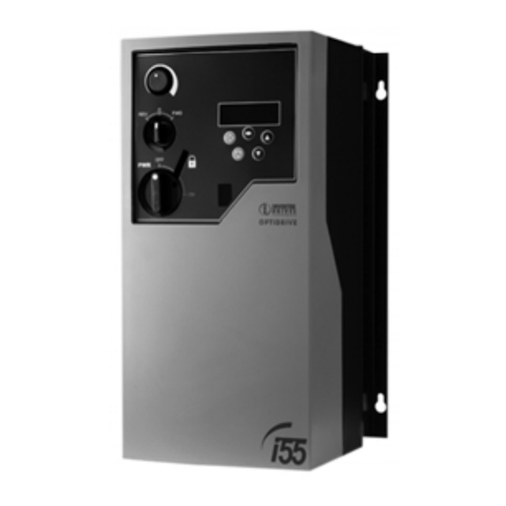
Page 33: Ip55 Enclosed Drive
11. IP55 Enclosed Drive 11.1. Overview Optidrive Plus 3GV is optionally available in an IP55 enclosed version for power ratings up to 4kW / 5HP. Un‐switched versions have no built in controls. Switched versions have built in local isolator, Potentiometer and control switch. 11.2. Models and Ratings 200‐240V ±10% ‐ 1 Phase Input – 3 Phase Output Model (kW) kW Model (HP) HP Frame Size Nominal Input Current Nominal Output Current Amps Amps ODP‐12037‐xx‐I55 0.37 ODP‐12005‐USA‐I55 0.5 1 6.7 2.3 ODP‐12075‐xx‐I55 0.75 ODP‐12010‐USA‐I55 1 1 12.5 4.3 ODP‐12150‐xx‐I55 1.5 ... -
Page 34: Dimensions And Mounting
11.4. Dimensions and Mounting Optidrive Plus IP55 Size 1 Layout, Dimensions and Mounting Height 200mm Footprint View Width 140mm Height 200mm Depth 162mm Width 140mm Weight 2.3Kg Depth 162mm Display A 141.5mm Keypad B 127.5mm IR Interface C 25mm Control Terminals Power Input Terminals Motor Output Terminals ... -
Page 35: Control Terminal Wiring - None Switched Version
11.6. Control Terminal Wiring – None Switched Version Wiring configuration and terminal connections for the none switched IP55 version are identical to those of the IP20 version, as shown in section 4.7 on page 11. 11.7. IP55 / Nema 12K Switched Version ‐ Wiring diagram for in‐built switches Note: Purple wire can be moved from terminal 1 (default) to terminal 2 ... - Page 36 Supply Voltage ‐ 200 – 240 Volt + / ‐ 10%, 1 or 3 Phase ‐ 380 – 480 Volts + / ‐ 10%, 1 or 3 Phase ‐ 480 – 525 Volts + / ‐ 10%, 3 Phase ‐ 500 – 600 Volts + / ‐ 10% See Page 5 Fuses or MCB & Cable Sizes ‐ Check drive rating information on page 27 Keypad operation – see page 14 Control Terminal Wiring – based on default settings :‐ Motor Cable Sizes ‐ Check drive rating information on page 27 Motor Connections ‐ Check for Star or Delta (see page 10) Motor Nameplate Details ‐ Enter the motor rated voltage(V) in P1‐07 ‐ Enter the motor rated current (A) in P1‐08 ‐ Enter the motor rated frequency (Hz) in P1‐09 36 Optidrive Plus 3 User Guide www.invertek.co.uk ...
Need help?
Do you have a question about the Optidrive Plus 3GV and is the answer not in the manual?
Questions and answers