Advertisement
Advertisement
Table of Contents

Related Manuals for Invertek Drives OPTIDRIVE P2


Summary of Contents for Invertek Drives OPTIDRIVE P2
- Page 1 2017 SERVICE MANUAL ODP-2/HVAC FRAME SIZE 3 Page 1 of 10...
-
Page 2: Table Of Contents
SERVICE MANUAL ODP-2/HVAC FRAME SIZE 3 2017 Contents Page IP20 drive disassembly procedure ....................3 Cover removal procedure ........................3 Fan disconnection ..........................6 Fan removal/assembly ........................7 Heatsink removal ..........................7 Output terminal connector removal ....................9 Filter PCB removal ..........................9 Page 2 of 10... -
Page 3: Ip20 Drive Disassembly Procedure
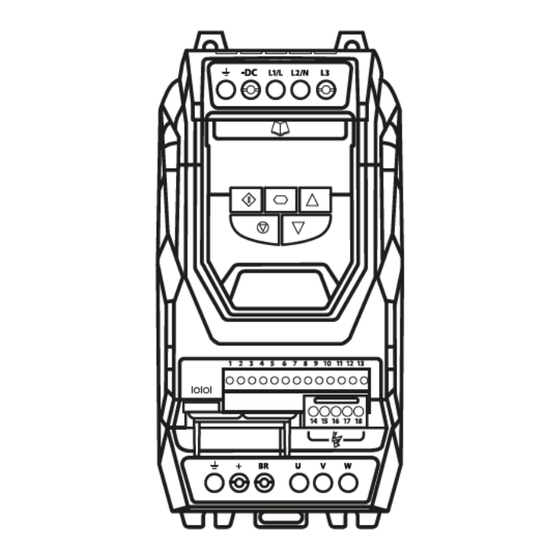
SERVICE MANUAL ODP-2/HVAC FRAME SIZE 3 2017 IP20 drive disassembly procedure Cover removal procedure Place the drive on a surface that will prevent damage to the plastics Remove option cover plate if fitted by pulling the cover away from the drive in the direction highlighted Remove pluggable terminal connector by pulling the... - Page 4 SERVICE MANUAL ODP-2/HVAC FRAME SIZE 3 2017 The example opposite shows the plastic cover after it has been clicked out of position With the cover removed, access can now be made through the terminal section of the drive The end of a wooded brush will be used to remove the plastics cut to a wedge shape.
- Page 5 SERVICE MANUAL ODP-2/HVAC FRAME SIZE 3 2017 Using the wooden wedge, push the plastic tab in while pulling the cover away in the direction indicated Using the wooden wedge, push the plastic tab in while pulling the cover away in the direction indicated Once both taps are clear turn the drive over and repeat the...
-
Page 6: Fan Disconnection
SERVICE MANUAL ODP-2/HVAC FRAME SIZE 3 2017 Start to remove the drive in the direction indicated but only a small amount to allow access to the fan lead on the right hand side of the drive During reassembly of the drive, ensure PCB fits into the plastics positioning groves only Fan disconnection... -
Page 7: Fan Removal/Assembly
SERVICE MANUAL ODP-2/HVAC FRAME SIZE 3 2017 Fan removal/assembly The fan sits in the groves highlighted opposite The fan label must always face inwards to ensure correct airflow through the drive Heatsink removal Remove Earth screw using a T20 torx screwdriver (Torque setting 1Nm) Page 7 of 10... - Page 8 SERVICE MANUAL ODP-2/HVAC FRAME SIZE 3 2017 Remove Earth screw using a T20 torx screwdriver (Torque setting 1Nm) Remove 2 x heatsink screws using a T25 torx screwdriver (Torque setting 1Nm) The white thermistrate on heatsink is fragile so placed it in a location away from potential mechanical damage Placed disassembled drive on a...
-
Page 9: Output Terminal Connector Removal
SERVICE MANUAL ODP-2/HVAC FRAME SIZE 3 2017 Output terminal connector removal The output terminal connector can removed by removing the five screws highlighted using a T15 torx screwdriver (Torque setting 1Nm) The output terminal connector removed Filter PCB removal The filter PCB can be removed by removing the eight screws highlighted using a T15 torx screwdriver... - Page 10 SERVICE MANUAL ODP-2/HVAC FRAME SIZE 3 2017 The filter PCB removed Page 10 of 10...
Need help?
Do you have a question about the OPTIDRIVE P2 and is the answer not in the manual?
Questions and answers