
Related Manuals for Omron SJDE-ANA-OY


Summary of Contents for Omron SJDE-ANA-OY
- Page 1 OMRON YASKAWA Motion Control B.V. Manual No. TOEP-C71080603-01-OY JUNMA SERIES SERVO DRIVE Mechatrolink-II communications type Model: SJDE- ANA-OY USER´ S MANUAL...
- Page 2 Copyright 2006 YASKAWA ELECTRIC CORPORATION All rights reserved. No part of this publication may be reproduced, stored in a retrieval system, or transmitted, in any form, or by any means, mechanical, electronic, photo- copying, recording, or otherwise, without the prior written permission of Yaskawa. No patent liability is assumed with respect to the use of the information contained herein.
-
Page 3: Introduction
Safety Information The following conventions are used to indicate precautions in this manual. Failure to heed these precau- tions can result in serious or possibly even fatal injury or damage to the products or to related equipment and systems. Indicates precautions that, if not heeded, could possibly result in loss of life or seri- WARNING ous injury. -
Page 4: Notes For Safe Operation
Incorrect wiring may result in electric shock, fire, or damage to the equipment. For the wir- ing method, refer to 3.4 Main Circuit Wiring. • Use the emergency stop signal input E-STP to forcibly turn OFF the servo from an external sequence, such as host controller, at occurrence of servo alarm or system emergency stop. - Page 5 WARNING • Provide an appropriate stopping device on the machine side to ensure safety. A holding brake for a servomotor with brake is not a stopping device for ensuring safety. Failure to observe this warning may result in injury. • Do not come close to the machine immediately after resetting momentary power loss to avoid an unexpected restart.
- Page 6 • Do not step on or place a heavy object on the product. Failure to observe this caution may result in injury. • Do not cover the inlet or outlet parts of the SERVOPACK and prevent any foreign objects, such as metallic fragment, or combustibles from entering the product.
- Page 7 • Use the emergency stop signal input E-STP to forcibly turn OFF the servo from an external sequence, such as host controller, at occurrence of servo alarm or system emergency stop.
- Page 8 Failure to observe this caution may result in fire. • Do not bundle or run power and signal lines together in the same duct. Keep power and sig- nal lines separated by at least 300 mm. (11.81 in).
- Page 9 ON or soon after the power is turned OFF. Failure to observe this caution may result in burns due to high temperatures. • When an alarm occurs, remove the cause, turn OFF the power and ON again after confirm- ing safety, and then resume operation.
- Page 10 When this manual is revised, the manual code is updated and the new manual is published as a next edition. • If the manual must be ordered due to loss or damage, inform your nearest Omron Yaskawa repre- sentative or one of the offices listed on the back of this manual.
-
Page 11: Table Of Contents
Notes for Safe Operation - - - - - - - - - - - - - - - - - - - - - - - - - - - - - - - - - - - -... - Page 12 4.2.4 Write Parameter (PRM_WR: 02H) - - - - - - - - - - - - - - - - - - - - - - - - - - - - - - - - - - 62...
- Page 13 4.2.26 Constant Speed Feed (FEED: 36H) - - - - - - - - - - - - - - - - - - - - - - - - - - - - - - - - - 82...
- Page 14 8 Troubleshooting- - - - - - - - - - - - - - - - - - - - - - - - - - - - - - - - - - - - - - -...
-
Page 15: Before Use
1 Before Use 1.1 Checking Products Confirm that the following items have been delivered together with the SERVOPACK. Verify that the ordered product as received by the model number marked on the nameplate on the SERVOPACK. If you find any irregularities such as incorrect SERVOPACK model, damages, and missing parts or items, contact your Omron Yaskawa representative or the dealer from whom you purchased the prod- ucts. -
Page 16: Model Designation
Applicable servomotor capacity Code Output (W) Power supply voltage A: 200 VAC Interface specification N: MECHATROLINK-II Design revision order Sold by OMRON YASKAWA Motion Control B.V. 1.4 SERVOPACKs and Applicable Servomotors Rated Servomotors SERVOPACKs Output Without Brakes With Brakes 100 W... -
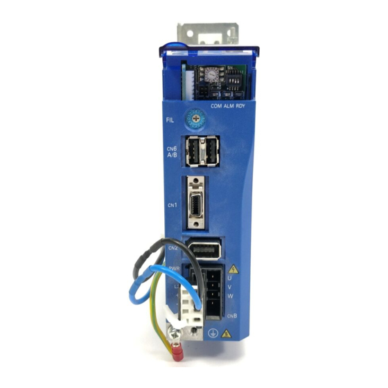
Page 17: Part Names And Functions
Ground terminal MECHATROLINK-II Communications Settings The SW1 and the SW2 switches set the MECHATROLINK-II communications settings. Settings that have been changed are enabled when the power is turned OFF and then ON again. DIP switch for MECHATROLINK-II communications setting (SW2) Rotary switch for MECHATROLINK-II Refer to 3.8 Setting MECHATROLINK-II... -
Page 18: Applicable Standards
A, group 1 SJME IEC60034-1 EN55011 EN61000-6-2 TUV PS* Servomotor IEC60034-5 class A, group 1 IEC60034-8 IEC60034-9 * TÜV Product Services GmbH Note: 1. Because SERVOPACKs and servomotors are built-in type, reconfirmation is required after being installed in the final product. -
Page 19: Installation
Pollution degree: 2 Protection class: IP1X (EN50178) Installation in a control Design the control panel size, unit layout, and cooling method so that panel the temperature around the SERVOPACK does not exceed 55 C. Note: To extend product life and maintain reli- ability, keep the temperature inside the control panel under 45 C. -
Page 20: Installation Method
This allows the units to cool. CAUTION • Do not cover the inlet or outlet parts of the SERVOPACK and prevent any foreign objects, such as metallic fragment, or combustibles from entering the product. -
Page 21: Wiring
(CNB). ( CNA ) Used for a regenerative unit. Regenerative unit Used if regenerative energy is high. To the control circuits of magnetic contactor * 1. Prepare a 24-VDC power supply for the brake separately from the sequence power supply. -
Page 22: Standard Connection
3.2 Standard Connection 3.2 Standard Connection Power supply Single-phase 200 VAC to 230 VAC 50/60Hz L1 L2 Molded-case circuit breaker Surge protector Noise AVR1* 24 VDC filter power supply + 24V 200 VAC to Brake Varistor 230 VAC SERVOPACK SW1 SW2... -
Page 23: Precautions On Wiring
(E-STP) that will stop operations without turning OFF the power supply. * 1. Prepare a 24 VDC power supply for sequence separately from the 24 VDC power supply for brake. 3.3 Precautions on Wiring WARNING •... -
Page 24: Caution For Cable
• For wiring, use the specified cables. Use cables that are as short as possible. • Do not bend or apply tension to cables. The conductor of a signal cable is thin (0.08 to 0.12 mm so handle the cables carefully. -
Page 25: Noise Prevention
Groudning: Ground to one point only. Min. grounding resistance: 100 * 1. For the wires connected to the casings for installation purposes, use wires with a diameter of 3.5 mm larger. Flat braided copper wires are recommended. * 2. Use twisted pair wires for section P. - Page 26 3.3 Precautions on Wiring Noise Filters Use a block type noise filters to prevent any noise interference from the power-supply line. The following table lists the recommended noise filters for several SERVOPACK models. Application of Noise Filters Power-Supply SERVOPACK Recommended Noise Filters...
- Page 27 3.3 Precautions on Wiring Filter dimensions for model R7A-FIZN109-BE...
-
Page 28: Installation And Wiring Conditions On Ce Marking
AC Line cable Shielded wire Attaching the Ferrite Core Coil the servomotor main circuit cable (as a connection) around the ferrite core with two turns, then attach them by the SERVOPACK. Refer to the diagram in the previous page. Cable (two turns) -
Page 29: Other Precautions
A shield box, which is a closed metallic enclosure, should be used for shielding magnetic interference (EMI). The structure of the box should allow the main body, door, and cooling unit to be attached to the ground. The box opening should be as small as possible. - Page 30 3.4 Main Circuit Wiring Wire Size and Allowable Current The following table shows the wire size and allowable current for three cables. Use a cable whose specifications meet or are less than allowable current in the table. • 600 V Heat-resistant Vinyl Cables (HIV)
- Page 31 3.4 Main Circuit Wiring Peripheral Devices List Name Specifications Type Length Appearance Manufac- turer 1.5 m Power cable Flexible cables JZSP-CHM000-01-5E Omron for Junma (standard) Yaskawa JZSP-CHM000-03-E servomo- UL/CSA listed Motion tors without Shielded cable JZSP-CHM000-05-E Control, brake Bending radius...
- Page 32 3.4 Main Circuit Wiring (cont’d) Name Specifications Type Length Appearance Manufac- turer 1.5 m Encoder Flexible cables JZSP-CHP800-01-5E Omron Cable for (standard) Yaskawa JZSP-CHP800-03-E Junma ser- UL/CSA listed Motion vomotors Shielded cable JZSP-CHP800-05-E Control, SMJE- Bending radius BV. *4 10 m...
- Page 33 * 4. Omron Yaskawa Motion Control BV. URL: http://www.omronyaskawa.com * 5. J.S.t.Mfg co., Ltd. URL: http://www.jst-mfg.com * 6. The total cable length must be 50 m (164 ft) max. and the cable length between stations 0.5 m (1.64 ft) min. * 7. Specify the cable length in when ordering as shown in the table below.
-
Page 34: Wiring Connector For The Power Supply/Regenerative Unit (Cna)
Tool must be purchased by the customer. • Use a standard flat-blade screwdriver (blade width of 2.5 to 3.0 mm (0.09 to 0.12 in)). Put the blade into the slot, as shown in Fig. B, and press down firmly to open the wire terminal. - Page 35 OFF the SERVOPACK power supply. Note: 1. Pull lightly on the wires to confirm that they are securely connected. 2. Make sure that none of the insulating sheaths of the wires are caught in the springs. Connector for Power Supply/Regenerative Unit (CNA) Pin No.
-
Page 36: Wiring Connector For The Servomotor Main Circuit Cable (Cnb)
Wiring Connector for the Servomotor Main Circuit Cable (CNB) Wire the connector for the servomotor main circuit cable (CNB) in the same way as the connector for the power supply/regenerative unit (CNA). Refer to 3.4.2 Wiring Connector for the Power Supply/ Regenerative Unit (CNA) for details and the procedure. - Page 37 The connection diagram for the standard cable (JZSP-CHM000- cable with connectors on both ends) is shown below. If the servomotor main circuit cable is prepared by the customer, refer to the diagram below and wire the cable correctly. Motor end...
- Page 38 3. Confirm pin numbers on the connector as well. 4. If using the servomotor to drive a vertical axis, configure a circuit to turn the holding brake ON and OFF so that the movable section will not be pulled down by gravity when the power supply of the SERVOPACK is turned OFF.
- Page 39 The connection diagram for the standard cable (JZSP-CHM030- cable with connectors on both ends) is shown below. If the servomotor main circuit cable is prepared by the customer, refer to the diagram below and wire the cable correctly. SERVOPACK end...
-
Page 40: Wiring The Encoder Connector (Cn2)
Connection Diagram for Standard Encoder Cable The connection diagram for the standard cable (JZSP-CHP800- cable with connectors on both ends) is shown below. If the encoder cable is prepared by the customer, refer to the diagram below and wire the cable correctly. Applicable wires SERVOPACK end For encoder power supply: AWG22 (0.33 mm... -
Page 41: Wiring The I/O Signal Connector (Cn1)
Connection Diagram for Standard I/O Cable (Supplied by Yaskawa Electric ) The connection diagram connection diagram for the standard cable (JZSP-CHI003- cable with connector) is shown below. If the I/O signal cable is prepared by the customer, refer to the diagram below and wire the cable correctly. SERVOPACK end... - Page 42 Wire a connector to match the controller if you are connecting to a Position Control Unit and a compatible cable is not available, or if the drive is connected to a control- ler manufactured by another company.
-
Page 43: Wiring The Mechatrolink-Ii Communication Connectors (Cn6A And Cn6B)
Directive) Cable Length The total cable length must be 50 m max. The cable length between stations must be 0.5 m min. Terminator Install a terminator on the SERVOPACK connected at the end of communication cable. Terminator Type... - Page 44 Cable length between stations: 0.5 m min. Max. number of slaves: 30 (with repeaters connected) IMPORTANT Keep a distance 300 mm min. between power lines (high-voltage circuit such as power sup- ply line and servomotor main circuit cable) and MECHATROLINK-II cable.
-
Page 45: Wiring The Personal Computer Connector (Cn9)
3.4 Main Circuit Wiring 3.4.7 Wiring the Personal Computer Connector (CN9) Prepare the specified cable to connect the SERVOPACK to a personal computer. Communication Cable Use the specified twisted-pare and shielded twisted cable. Type Model Length Personal Computer JZSP-CPS00-02 Cable... -
Page 46: Connection Examples Of Input Signal
3.3k Shield wire Twisted-pair wires IMPORTANT Prepare an external 24-VDC power supply. The 24-VDC power supply is not built into the SERVOPACK. • Specifications of the external power supply for sequence input signals: 24 VDC 1 V 50 mA min. -
Page 47: Connection Example Of Output Signal
3.6 Connection Example of Output Signal 3.6 Connection Example of Output Signal Set the load so that the output current will fall within 50 mA or less. Photocoupler output (Per output signal) Max. voltage: 30 VDC Max. current: 50 m ADC... -
Page 48: I/O Signals
The signal turns OFF. 3.7.2 External Latch Signal Input The usual connection for external latch signal input /EXT1 is shown below. This input signal is used for the homing (ZRET command) and the external signal input positioning (EX_POSING) functions of MECHATROLINK-II communications specifications. -
Page 49: Emergency Stop Signal Input
OFF (high level) Emergency stop (Forced servo OFF) • The command warning 1 (A.95A) will occur if a SV_ON command is sent while the SERVOPACK is in emergency stop status. • The emergency stop alarm (A.280) will occur if the emergency stop signal turns ON while the power is... - Page 50 Sequence at Occurrence of Emergency Stop WARNING • Configure the circuit’s power supply to be automatically cut off if E-STP signal is OFF at occur- rence of emergency stop. The residual voltage rotates the servomotor for a few seconds after the power supply has been turned OFF, and may result in injury or damage to the equipment.
-
Page 51: Forward/Reverse Run Prohibited Inputs (Overtravel Inputs)
Connect these signals to limit switches to forcibly stop the servomotor when the machine movable part travels beyond the allowable motion range. The servomotor will decelerate to a stop, and then the zero clamp is performed. The maximum torque during deceleration to a stop will be the servomotor maxi- mum torque. -
Page 52: Servo Alarm Output
The usual connection for brake interlock signal /BK is shown below. These signal turns ON when the servo turns ON, and OFF when the servo turns OFF. They are used to control the brake. The brake can also be released by sending a release brake (BRK_OFF) com- mand using MECHATROLINK-II communications. - Page 53 Brake (/BK) Brake OFF Brake ON Motor power Motor power ON Motor power OFF Approx. 130 ms When the servo is turned OFF while the servomotor is running. Servo OFF (SV_OFF) Servo ON Servo OFF command Motor speed (min Approx. 100 min...
-
Page 54: Setting Mechatrolink-Ii Communications
External Appearance JEPMC-W6022 JEPMC-W6022-E (Compliant with RoHS Directive) Repeaters A repeater is needed in the network, when the total distance between stations exceeds 30 m, or when the number of slave stations is 17 or more. Type External Appearance JEPMC-REP2000... -
Page 55: Setting Communications Specifications
Extended network 3.8.3 Setting Communications Specifications Setting Transmission Bytes The SW2 bit 2 switch sets the MECHATROLINK-II transmission bytes, as shown below. Settings that have been changed are enabled when the power is turned OFF and ON. 1 2 3 4... -
Page 56: Transmission Cycle And Number Of Stations
3.8 Setting MECHATROLINK-II Communications 3.8.4 Transmission Cycle and Number of Stations The transmission cycle and number of stations that can be set with the SERVOPACK are shown below. Transmission Bytes Transmission Cycle 1.5 ms 2.0 ms 3.0 ms 4.0 ms 1.0 ms... -
Page 57: Mechatrolink-Ii Commands
4.1 Lists of Commands 4 MECHATROLINK-II Commands 4.1 Lists of Commands 4.1.1 Main Commands List The MECHATROLINK-II main commands are classified into three types: Common commands, com- mon motion commands, and servo standard commands Classifica- Com- Command Functions Process- Synchroni-... - Page 58 M: Motion command X: Compound command IMPORTANT If an unsupported command is received, the warning A.95b will occur, and the command will be ignored. The servo is not OFF and the servomotor is not stopped if an unsupported command is received.
-
Page 59: Subcommands List
4.1 Lists of Commands 4.1.2 Subcommands List Command Command Functions Remarks Code Name No Operation PRM_RD Read Parameter PRM_WR Write Parameter ALM_RD Read Alarm or Warning PPRM_WR Write Stored Parameter LTMOD_ON Request Latch Mode LTMOD_OFF Release Latch Mode SMON Status Monitoring... -
Page 60: Main Commands
MECHATROLINK-II during normal operations. The C1 master station phases described here indi- cate the communication state of the C1 master station in relation to the slave stations, but do not indi- cate the state of the C1 master station device. - Page 61 The slave stations exchange data and the control of devices by the commands sent from the C1 master station. The transition to phase 3 or phase 4 is performed by commands from the C1 master station to the slave stations.
-
Page 62: No Operation (Nop: 00H)
STATUS • Returns the status of the ALM, WARNG, and CMDRDY in STATUS bytes only. All other bits are not used. The response will be NOP when the power is turned ON until initialization has been completed, and dur- ing this time, the following status will be returned: CMDRDY: 0. -
Page 63: Read Parameter (Prm_Rd: 01H)
(The set value is enabled with the Setup Device command (CONFIG).) • A warning will occur and the command will be ignored in the following cases. If a warning occurs, PARAMETER will not be dependable. -If NO is not within range: Data setting warning 1 (A.94A) -
Page 64: Write Parameter (Prm_Wr: 02H)
A written parameter is enabled with the Setup Device command (CON- FIG) transmission after setting. • Can be used during phases 2 and 3. • A warning will occur and the command will be ignored in the following cases. SIZE... -
Page 65: Read Id (Id_Rd: 03H)
Note: 1. Model numbers appear in ASCII code, with the last section as “00.” 2. Spaces indicate unspecified data. 3. The version number of the encoder software is set to 00 (binary) and cannot be changed. * 1. Rated output. -
Page 66: Setup Device (Config: 04H)
• The SERVOPACK will change to Servo OFF if this command is received when the SERVOPACK is Servo ON. • A warning will occur and the command will be ignored in the following cases. -If parameters are changed mid-operation with CX-Drive: Command warning 1 (A.95A) -
Page 67: Read Alarm Or Warning (Alm_Rd: 05H)
• A warning will occur and the command will be ignored in the following cases. -If ALM_RD_MOD is not within range: Data setting warning 2 (A.94B) RWDT * Alarm occurrence history is saved in non-volatile memory, and will not be lost if power goes OFF. Details of ALM_RD_MOD ALM_RD_MOD Description... -
Page 68: Clear Alarm Or Warning (Alm_Clr: 06H)
4.2 Main Commands Each alarm code of the JUNMA-series SERVOPACK is 2-byte long. The data format of alarm code is as follows. D15-D12 D11-D4 D3-D0 Reserved (0) Alarm code Detailed information Note: 1. When ALM_RD_MOD = 0 or 1, the alarm code (1-byte long) is returned. -
Page 69: Start Synchronous Communication (Sync_Set: 0Dh)
-MECHATROLINK-II Synchronization Error (A.E50) -MECHATROLINK-II Synchronization Failure (A.E51) -MECHATROLINK-II Communications Error (A.E60) -MECHATROLINK-II Transmission Cycle Error (A.E61) • In the following case, a warning will occur and the command will be ignored. -During operation using CX-Drive: Command warning 1 (A.95A) RWDT... -
Page 70: Establish Connection (Connect: 0Eh)
Data setting warning 2 (A.94B) -During operation using CX-Drive: Command warning 1 (A.95A) • The only commands that will be accepted are CONNECT, DISCON- NECT, and NOP. If any other command is issued, NOP will be sent as a RWDT response. -
Page 71: Release Connection (Disconnect: 0Fh)
-If NO is not within range: Data setting warning1 (A.94A) -If SIZE does not match:Data setting warning 4 (A.94D) -If PARAMETER is not within range: Data setting warning 2 (A.94B) • For details on NO, SIZE and PARAMETER, refer to 7.2 List of Parame- ters. RWDT... -
Page 72: Set Coordinates (Pos_Set: 20H)
Decides the coordinates, and ZPOINT (home position) and software limits are enabled. • POS_SEL: Selects coordinates. 3: Sets POS_DATA to the reference point and the coordinate system (POS, MPOS, APOS, IPOS, and TPOS) if APOS (machine coordinate system feedback position) is selected (The “3: APOS” can only be selected for POS_SEL.). - Page 73 Subcommand Cannot be used nications cycle STATUS • Turns OFF the brake signal and locks the brake. This command is enabled only while the servo is OFF. • Can be used during phases 2 and 3. MONITOR • Brake signal output timing...
-
Page 74: Release Brake (Brk_Off: 22H)
IMPORTANT BRK_ON and BRK_OFF become always valid as commands unless a warning occurs. If a BRK_OFF command is sent while power is being supplied to the servomotor, the servo- motor continues running. However, if a Servo OFF command is sent later, the brake will remain released because the BRK_OFF command is valid and may cause a critical situation. -
Page 75: Turn Sensor On (Sens_On: 23H)
• The reference point, home position (ZPOINT), and software limits will be disabled. • Can be used during phases 2 and 3. MONITOR • A warning will occur and the command will be ignored in the following case. -While the SERVOPACK is servo ON: Command warning 1 (A.95A) MONITOR... -
Page 76: Stop Motion (Hold: 25H)
Subcommand Can be used nications cycle OPTION STATUS • Stops the servomotor for positioning according to the stop method set in HOLD_MOD. • From current motion status, performs a deceleration stop and position- HOLD_ MONITOR1 ing according to the deceleration speed set in the parameters. -
Page 77: Request Latch Mode (Ltmod_On: 28H)
Subcommand Cannot be used nications cycle STATUS • Sets the modal latch mode. If a latch signal is input during modal latch mode, position latching will be performed. • Can be used during phases 2 and 3. MONITOR1 • A latch signal can be selected using LT_SGN. Refer to Latch Signal Field Specifications (LT_SGN). -
Page 78: Release Latch Mode (Ltmod_Off: 29H)
STATUS • Releases the modal latch mode. • Can be used during phases 2 and 3. • Check that CMDRDY is 1 to confirm that the Release Latch Mode com- MONITOR1 mand has been received. • Interference with another latch mode command -During the execution of a command such as LATCH, ZRET, or EX_POSING, the LTMOD_OFF command cannot be used. -
Page 79: Status Monitoring (Smon: 30H)
ALARM Processing time Within commu- Subcommand Can be used nications cycle STATUS • Reads the current status of the SERVOPACK. • Can be used during phases 2 and 3. MONITOR1 MONITOR2 SEL_MON SEL_MON IO_MON RWDT For sub- For sub- commands. -
Page 80: Servo On (Sv_On: 31H)
STATUS • Turns ON the power to the motor. • Can be used during phases 2 and 3. • A warning will occur and the command will be ignored in the following MONITOR1 cases. -During alarm occurrence (when ALM of STATUS is 1): Command warning 1 (A.95A) -
Page 81: Servo Off (Sv_Off: 32H)
ALARM Processing time Within 50 ms Subcommand Can be used STATUS • Turns OFF the power to the motor. • Can be used during phases 2 and 3. MONITOR1 MONITOR2 SEL_MON SEL_MON IO_MON RWDT For sub- For sub- commands. -
Page 82: Interpolation Feed (Interpolate: 34H)
OPTION STATUS • Starts interpolation feeding every communications cycle. • Can be used during phase 3. • A warning will occur and the command will be ignored in the following TPOS MONITOR1 cases. -During phase 2: Command warning 1 (A.95A) -If the SERVOPACK is Servo OFF: Command warning 1 (A.95A) -
Page 83: Positioning (Posing: 35H)
TSPD MONITOR2 • The target position (TPOS) is a signed 4 bytes. It is sent by using an absolute position in the reference coordinate system. • The target speed (TSPD) is an unsigned 4 bytes. It is sent in the range from 0 to the maximum speed [reference unit/s]. -
Page 84: Constant Speed Feed (Feed: 36H)
• OPTION field cannot be used. Set all bits to 0. • The target speed (TSPD) is a signed 4 bytes. The direction is deter- mined by the sign. The target speed is sent in the range from a negative maximum speed to a positive maximum speed [reference unit/s]. -
Page 85: Interpolation Feeding With Position Detection (Latch: 38H)
STATUS • Performs interpolation feeding and latches the position using the latch signal specified in LT-SGN. • If the latch signal is input, the position when the signal is received is TPOS MONITOR1 recorded as the feedback latch position (LPOS) of the machine coordi- nate system, and the LPOS will forcibly be indicated as the MONITOR2 for one communications cycle. -
Page 86: External Input Positioning (Ex_Posing: 39H)
• The target position (TPOS) is a signed 4 bytes [reference unit]. It is sent by using an absolute position in the reference coordinate system. • The target speed (TSPD) is an unsigned 4 bytes. It is sent in the range SEL_MON SEL_MON from 0 to the maximum speed [reference unit/s]. -
Page 87: Homing (Zret: 3Ah)
Latching Area Upper Limit Pn822 Latching Area Lower Limit Operation If a latch signal is input, positioning is performed for the position calculated with the following equation: latch signal input position (LPOS) + final travel distance for external positioning specified in Pn814. - Page 88 • OPTION field cannot be used. Set all bits to 0. IO_MON • The target speed (TSPD) is an unsigned 4 bytes. It is sent in the range from 0 to the maximum speed [reference unit/s]. • Before DEC is input, the target speed during motion can be changed.
-
Page 89: Adjusting (Adj: 3Eh)
Linear Deceleration Parameter Pn816 Homing Direction Pn817 Homing Approach Speed 1 Pn818 Homing Approach Speed 2 Pn819 Final Travel Distance for Homing Pn820 Latching Area Upper Limit Pn822 Latching Area Lower Limit Operation Reference speed Homing Approach Speed 1 (Pn817) - Page 90 STATUS • This command is for maintenance. Parameter initialization can be done. • Use as SUBCODE = 01H. • Refer to the next page, for the way to use set this command. CCMD CANS • A command warning will occur and the command will be ignored in the following cases.
- Page 91 CSIZE = 0002H (size = 2H: fixed) CDATA = 1005H (operation mode = 1005H: fixed) After sending the data, wait until CMDRDY of STATUS is equal to 1, and check ERRCODE to confirm that no error occurred. 2. Execute the parameter initialization.
-
Page 92: Subcommands
SERVOPACK. The MECHATROLINK-II subcommands can be used by specifying them with the CONNECT com- mand when MECHATROLINK-II communications starts. They use the seventeenth to the twenty-ninth bytes of the command and response data. 4.3.1 No Operation (NOP: 00H) Byte Description... -
Page 93: Write Parameter (Prm_Wr: 02H)
Data communi- Processing time Within 100 ms classifications cations com- mand group SUBSTATUS • Writes a parameter. This command has the same function as the main command PRM_WR. SIZE SIZE PARAME- PARAME- 4.3.4 Read Alarm or Warning (ALM_RD: 05H) Byte... -
Page 94: Write Stored Parameter (Pprm_Wr: 1Ch)
Data communi- Processing time Within 200 ms classifications cations com- mand group SUBSTATUS • Writes a parameter. This command has the same function as the main command PPRM_WR. SIZE SIZE PARAME- PARAME- 4.3.6 Request Latch Mode (LTMOD_ON: 28H) Byte LTMOD_ON... -
Page 95: Release Latch Mode (Ltmod_Off: 29H)
Command Response Processing Data communi- Processing time Within commu- classifications cations com- nications cycle mand group SUBSTATUS • Reads the monitoring information specified in SEL_MON3/4. This command has the same function as the main command SMON. SEL_MON SEL_MON MONITOR3 MONITOR4... -
Page 96: Combination Of Mechatrolink-Ii Main Commands And Subcommands
A.95E (see 8.3.2 Warning Display and Troubleshooting for details.) will occur, and the command will be ignored. The servo is not OFF and the servomotor is not stopped if a command with a subcommand that cannot be combined is received during operation. -
Page 97: Command Data Field
The latch signal field specifications (LT_SGN) can be designated using the following commands: LATCH, EX_POSING, ZRET, LTMOD_ON The latch signal field is used to select latch signals for position data, with the second byte of the above main commands, or the eighteenth byte reserved area of the subcommands. -
Page 98: Status Field Specifications: Status
4.5 Command Data Field 4.5.3 Status Field Specifications: STATUS The status field is used to monitor the Servo status with the third to fourth byte reserved area of the main commands. Refer to the following table for details on bit allocation. - Page 99 Indicates the status of the main power supply. Status Main power supply OFF Main power supply ON D4 will remain set to 0 and the main power supply will be turned OFF for a maximum of 300 ms. INFO INFO Home position (ZPOINT) Indicates if the feedback position (APOS) is within or outside the home position range.
- Page 100 (Pn522) Status Other than the status 1. Output completion (DEN = 1) and the feedback position (APOS) are within the positioning complete range. The positioning complete width can be set in the following parameter. The setting will be immediately written in the SERVOPACK.
- Page 101 Latch completed (During execution of latch-related command). When the power supply is turned ON, the setting of D10 changes to 0. INFO INFO If a LATCH or EX_POSING command is changed to another command, latching is cancelled and the setting of D10 is changed to 1.
- Page 102 4.5 Command Data Field Positioning proximity (NEAR) Indicates whether the feedback position (POS) is within or out of the positioning proximity range. Positioning proximity range Within range Machine coordinate system APOS Target position Positioning proximity width (Pn524) Status The feedback position (APOS) is outside the positioning proximity range.
-
Page 103: Monitor Selection And Monitor Information Field Specifications
Reference units/s CSPD Reference speed Reference units/s TSPD Target speed Reference units/s Torque reference (The rated torque is 100%.) * For the items to be monitored for the SEL_MON commands (1 to 4), assign their monitor codes to the parame- ter. - Page 104 Position Speed status control control TPOS TSPD IPOS CSPD MPOS Feedback Electronic APOS FSPD Counter gear Electronic LPOS Counter gear LATCH signal * With a Junma-series SERVOPACK, position reference filter can be set using the FIL rotary switch or Pn00A.
-
Page 105: Io Monitor Field Specifications: Io_Mon
SMON, SV_ON, SV_OFF, HOLD, INTERPOLATE, FEED, POSING, LATCH, EX_POSING, ZRET, SENS_ON, SENS_OFF, BRK_ON, BRK_OFF, LTMOD-ON, LTMOD-OFF The IO monitor field is used to monitor the I/O signal status of the SERVOPACK, with the fourteenth to fif- teenth byte reserved area of the above main commands. -
Page 106: Substatus Field Specifications: Substatus
Indicates the emergency stop switch input signal status. Status Emergency stop switch input OFF Emergency stop switch input ON 4.5.6 Substatus Field Specifications: SUBSTATUS The substatus field is used to monitor the subcommand status with the eighteenth byte reserved area of the subcommands. Substatus Field SBCM- SBWARNG... -
Page 107: Alarm/Warning Field Specifications: Alarm
4.5 Command Data Field 4.5.7 Alarm/Warning Field Specifications: ALARM The alarm/warning field is the second byte of main command response. The SERVOPACK sets an alarm or warning code in this byte and returns the response. To monitor detailed information on alarms or warnings, use a command (ALARM_RD: 05H) Read Alarm/Warning or CX-Drive. - Page 108 Communications Error munications. MECHATROLINK-II The transmission cycle has changed during MECHATROLINK-II Transmission Cycle Error communications. Overload This warning occurs before the overload alarm (A.710 or A.720) occurs. If the warning is ignored and operation continues, an over- load alarm may occur.
- Page 109 Alarm Alarm Name Meaning Display of Response MECHATROLINK-II Data An incorrect parameter number was set in the command. Setting Warning 1 MECHATROLINK-II Data The command data is out of range. Setting Warning 2 MECHATROLINK-II Data Unmatched data size was detected.
-
Page 110: Command And Response Timing
4.6 Command and Response Timing 4.6 Command and Response Timing This section describes the execution timing for command data and the input timing for monitor data. This timing is constant, regardless of the transmission cycle and communications cycle. 4.6.1 Command Data Execution Timing Motion commands (POSING, INTERPOLATE) and the OPTION (command data field) are executed 625 s after they are received. -
Page 111: Operation Sequence
When the parameters are managed by a controller, the parameters are transmitted to a controller when the power is turned ON. With this operation sequence, the settings of the SERVOPACK do not need to be changed when the SERVOPACK is replaced. The following table shows the procedure. -
Page 112: Operation Sequence For Managing Parameters
* If communication disconnects normally, the NOP command is sent. If communication does not disconnect nor- mally, the DISCONNECT command is sent for two or more communications cycles prior to connection, then the CONNECT command is sent. -
Page 113: Operation Sequence To Turn The Servo On
Operations When an Emergency Stop Signal is Input Monitor the alarm status or SVON = 0 in STATUS field in the same way as at occurrence of alarm. If an error is detected, send a command such as SV_OFF and HOLD. During emergency stop, monitor the SERVOPACK status using SMON command, etc. - Page 114 500 ms* Motor stopped E-STP Signal OFF Restart of operation System recovery sequence ALM_CLR command SV_OFF, HOLD command etc. * /BK signal is output when the motor speed reaches 100 min or when 500 ms elapses after the servo turns OFF.
-
Page 115: Trial Operation
5 Trial Operation CAUTION • Conduct trial operation on the servomotor alone with the motor shaft disconnected from machine to avoid any unexpected accidents. Failure to observe this caution may result in injury. • During the JOG operation and the home position search operation using CX-Drive, the forward run prohibited (P-OT), reverse run prohibited (N-OT), and emergency stop (E-STP) signals will be ignored. - Page 116 (cont’d) Procedure Descriptions 3. Set and confirm the SERVOPACK station • Use SW1 and bit 3 of SW2 to set the station address (axis address). Refer to 3.8.3 Setting Communica- address. tions Specifications. When using the factory setting, check the setting as well.
- Page 117 (cont’d) Procedure Descriptions • In the Drive Type Settings menu enter your Junma Servo Drive details and confirm with OK. • Now select the suitable connection type and click on Connection Type settings to specify the details.
- Page 118 • Click on connect button to go online with the Junma. • Select “Test Run” from the tuning category in the Tree view pane • A warning message will be displayed by default • The Test Run View will appear •...
- Page 119 Click the Servo Off button to disable the servo. 2. Run for n cycles (where you can set up to 10 differ- ent steps for a complex run operation). When you select “Run for n cycles the second tab “Run Cycles”...
-
Page 120: Functions
6.1 Filter Setting 6 Functions 6.1 Filter Setting The factory setting for a filter can be normally used without changing. Change the setting if there are problems such as overshoot. There are two ways to set a filter. Use the SW2 bit 4 to select the setting method. -
Page 121: Switching Servomotor Rotation Direction
With the Reverse Rotation Mode, only the direction of servomotor rotation can be reversed. In this case, the physical direction of shaft motion is reversed. The polarity of the monitor data from the SER- VOPACK such as feedback position or feedback speed is not changed. -
Page 122: Electronic Gear
The electronic gear function enables the servomotor travel distance per input reference pulse from host controller to be set to any value. One reference pulse from the host controller is the minimum unit and is called as one reference unit. - Page 123 6.3 Electronic Gear 3. Determine the reference unit to be used. The reference unit is the minimum unit of the position data to move the load. (The minimum unit for ref- erences from host controller.) To move a table in 0.001 mm units Reference unit: 0.001 mm...
- Page 124 6.3 Electronic Gear 6. Set the parameters. Reduce the electronic gear ratio ( ) to the lower terms so that both A and B are integers smaller than 1073741824, then set A and B in the respective parameters. Pn20E Electronic gear ratio (Numerator)
-
Page 125: Position Management
6.4 Position Management 6.4 Position Management Range of Position Data The position data length used by MECHATROLINK-II is 4 bytes. During infinite-length operation where the position data length exceeds 4 bytes, the data becomes as shown below. MECHATROLINK position data... -
Page 126: Motion Commands
POSING related commands are as follows: POSING, FEED, EX_POSING, ZRET, HOLD POSING related commands execute positioning to the target position (TPOS) at the target speed (TSPD) with acceleration/deceleration set in parameters. Use the parameters listed below to set asymmetric acceleration/deceleration. -
Page 127: Software Limit Function
6.6.1 Conditions Needed to Enable the Software Limit Function The software limits are detected under the following conditions. Under all other circumstances, they will not be detected and the software limit monitor in STATUS field will be fixed to 0. 1. The homing (ZRET) operation has been completed. -
Page 128: Monitoring Software Limit
Software Limit Function (Pn801.0) Enable or disable the software limits. The software limit function will not be performed in the direction for which the software limit function is disabled and the software limit monitor in the STATUS field will be fixed to 0. -
Page 129: Latching Area
The latching area is between the latching area lower limit and latching area upper limit including the set value. Pn822 Pn820 Latching area 2. When Pn820 Pn822 The latching area is the latching area lower limit or above, or the latching area upper limit or below. Pn820 Pn822 Latching area Latching area... -
Page 130: Parameters
To edit a certain parameter, select the desired parameter in the grid, and enter the new parameter value. Once you have entered the new value click the “ENTER” key, or the “DOWN” arrow key, or simply select another parameter and the last edited parameter will be downloaded automatically to the Servopack. -
Page 131: List Of Parameters
A: Immediately validated after setting or changing B: Validated when DEN = 1 (Do not change when DEN = 0. If any change is made when DEN = 0, safe operation cannot be secured.) C: Validated when the power supply is turned OFF and then ON again, or by sending CONFIG com- mand. - Page 132 Do not change. Reserved Do not change. Reserved Do not change. P-OT Signal Mapping Forward run enabled when CN1-4 input signal is ON (L-level). Always sets the signal to ON to enable forward run. Pn50B 8883H 8888H — 8883H — Input Signal...
- Page 133 Reserved Do not change. Reserved Do not change. E-STP Signal Mapping Emergency stop when C1-6 input signal is OFF (H-level). Always sets the signal to ON to disable emergency stop. Reserved Do not change. Pn522 1073741824 1 reference Positioning...
- Page 134 Application 6 (Software LS) digit digit digit digit Software Limit Function Forward and reverse software limits enabled. Forward software limit disabled. Reverse software limit disabled. Software limits disabled in both directions. Reserved Do not change. Software Limit Check Using References...
- Page 135 7.2 List of Parameters (cont’d) Param- Name Data Min. Max. Units Factory Set- Valida- Refer- eter Size Set Value Set Value ting tion ence Page 0000H 0001H — 0000H Pn816 Homing Mode Setting digit digit digit digit Homing Direction Forward...
-
Page 136: Troubleshooting
8 Troubleshooting If the servomotor does not run or stop properly during operation in combination with the JUNMA series SERVOPACK, refer to the troubleshooting guide in this chapter and take corrective action. Contact your Omron Yaskawa representative if the problem cannot be solved by this method. - Page 137 Alarms The currently occurring alarm can be monitored usingCX-Drive. Connect a personal computer with CX-Drive installed to the SERVOPACK, and select Alarm Display from the project tree pane.
-
Page 138: Alarm Displays
8.1 Alarm Displays Alarm displays, names, and meanings are listed below. If an alarm occurs, the servomotor can be stopped by doing either of the following operations. • Stop by dynamic brake: Stops the servomotor immediately using the dynamic brake. - Page 139 Incorrect Polarity The servomotor polarity signal was incor- DB stop Detection rectly detected. A.C90 Encoder Signal Error The amplitude of encoder output signal is DB stop faulty. A.d00 Position Error Pulse The position error exceeded the parame- DB stop Available Overflow ter.
-
Page 140: Warning Displays
8.2 Warning Displays 8.2 Warning Displays Warning displays, with their names and meanings, are listed below. Warning Warning Name Meaning Display A.910 Overload This warning occurs before the overload alarm (A.710 or A.720) occurs. If the warning is ignored and operation continues, an overload alarm may occur. -
Page 141: Alarm/Warning Display And Troubleshooting
8.3 Alarm/Warning Display and Troubleshooting 8.3 Alarm/Warning Display and Troubleshooting The corrective actions when an alarm or warning occurs are described below. Contact your Omron Yaskawa representative if the problem cannot be solved by the described correc- tive actions. 8.3.1 Alarm Display and Troubleshooting... - Page 142 • Between the grounding Note: Always confirm that and U, V, or W of the ser- there is no short circuit or vomotor main circuit cable ground fault before turning ON the power supply again.
- Page 143 Overvoltage Occurred when the The AC power supply volt- Keep the AC power supply power supply was age is 290 V or more. voltage to the specified range. turned ON. The SERVOPACK is faulty. • Replace the SERVOPACK. • Contact your Omron Yaskawa representative.
- Page 144 • Replace the SERVOPACK. power supply was • Contact your Omron turned ON. Yaskawa representative. Occurred when the The order of phases U, V, Correct the servomotor main servomotor started and W of the servomotor circuit cable wiring. running or ran at wiring is incorrect.
- Page 145 • Contact your Omron Yaskawa representative. Occurred while the The effective torque excee- Reconsider the load and oper- servomotor was ds the rated torque, or the ation conditions. running. starting torque largely exceeds the rated torque. The SERVOPACK is faulty.
- Page 146 • Reconsider the servomotor capacity. The ambient temperature Correct the installation condi- around the SERVOPACK is tions so that the ambient tem- 55 C or more. perature around the SERVOPACK is kept to 55 C max. The SERVOPACK is faulty.
- Page 147 • Contact your Omron Detected turned ON. Yaskawa representative. Occurred when the The order of phases U, V, Correct the servomotor main servo was turned and W in the servomotor circuit cable wiring. ON or when the ref- wiring is incorrect.
- Page 148 MECHA- Occurred when Communications with the Turn the power supply OFF A.EA2 TROLINK-II MECHATROLINK-II host controller disconnected and then ON again, or send a Internal communications while the MECHATROLINK- DISCONNECT command to II connection was estab- Synchroni- started or during...
- Page 149 A.E60 MECHA- Occurred when Communications with the Turn the power supply OFF TROLINK-II MECHATROLINK-II host controller disconnected and then ON again, or send a Communi- communications while the MECHATROLINK- DISCONNECT command to II connection was estab- cations started or during...
- Page 150 MECHA- Occurred when Communications with the Turn the power supply OFF TROLINK-II MECHATROLINK-II host controller disconnected and then ON again, or send a Transmis- communications while the MECHATROLINK- DISCONNECT command to II connection was estab- sion Cycle started or during...
-
Page 151: Warning Display And Troubleshooting
Data Setting sent. command data. Warning 2 A.94d MECHA- Occurred when The data size that was set in Set a value with a correct data TROLINK-II ID_RD, PRM_RD, the command data is incor- size. Data Setting PRM_WR, rect. - Page 152 Warning started or during MECHATROLINK-II data Take measures against noise. communications. reception error occurred • Reconsider wirings for because of noise interfer- MECHATROLINK-II communi- ence. cations cable and FG. • Attach a ferrite core to the MECHATROLINK-II communi- cations cable.
-
Page 153: Troubleshooting For Malfunction Without Alarm Display
8.4 Troubleshooting for Malfunction without Alarm Display 8.4 Troubleshooting for Malfunction without Alarm Display Troubleshooting for malfunctions that cause no alarm display on the host controller and CX-Drive con- nected to the SERVOPACK through MECHATROLINK-II communications is listed below. Contact your Omron Yaskawa representative if the problem cannot be solved by the described correc- tive action. - Page 154 Keep the ambient tempera- overheated. high. perature around the servo- ture around the servomotor motor is 40 C max. to 40 C max. (Use fan or air conditioner.) Insufficient ventilation Check if ventilation is not Maintain proper ventilation. obstructed. Overloaded Rotate the servomotor with- Reduce the load.
- Page 155 8.4 Troubleshooting for Malfunction without Alarm Display (cont’d) Malfunction Cause Inspection Corrective Actions The emer- The switch for the external Check the switch for the Repair the switch for the gency stop emergency stop input is external emergency stop external emergency stop function does faulty or incorrect wiring.
- Page 156 8.4 Troubleshooting for Malfunction without Alarm Display (cont’d) Malfunction Cause Inspection Corrective Actions Abnormal Excessive vibration and Check if the vibration from Reduce the machine vibra- noise from the shock to the encoder the machine occurred or if tion, or secure the servomo-...
- Page 157 8.4 Troubleshooting for Malfunction without Alarm Display (cont’d) Malfunction Cause Inspection Corrective Actions Overtravel (OT) Excessive noise interfer- Check if the encoder cable Change the encoder cable ence to the encoder cable is not bundled with or too layout so that no surge volt- (Movement closed to high-voltage lines.
-
Page 158: Inspections
The following electric or electrical parts are subject to mechanical wear or deterioration over time. If an unusual noise or vibration occurs, refer to the life expectancy table and contact your Omron Yaskawa representative. After examining the part in question, we will determine whether the parts should be replaced or not. -
Page 159: Replacement Of Cooling Fan
9.3 Replacement of Cooling Fan CAUTION • Do not open the SERVOPACK case for 5 minutes after the power supply indicator (PWR LED) goes out. High voltage may remain in the SERVOPACK after the power supply has been turned OFF. - Page 160 9.3 Replacement of Cooling Fan 3. Lift up to remove the case. Case Cover 4. Disconnect the cooling-fan cable from the fan connector on the Lift the cable up, and then pull it out. SERVOPACK. 5. Unscrew the cooling fan and remove it.
- Page 161 (B) circled here. Arrow on the heat sink Arrows on the cooling fan 7. Secure the new cooling fan to the SERVOPACK with mounting screws. 8. Connect the cooling-fan cable to the fan connector on the SERVO- PACK.
- Page 162 PACK. Insert the tip of a flathead screw- driver into the two notches on the SERVOPACK one at a time and pry the hooks loose. 3. Remove the case. Lift up to pull the case of the SER- VOPACK off.
- Page 163 9.3 Replacement of Cooling Fan 4. Remove the six mounting screws. Mounting screws 5. Disconnect the cooling-fan cable Lift the cable up, from the fan connector on the and then pull it out. SERVOPACK. 6. Remove two mounting screws on Mounting screws the cooling fan.
- Page 164 ( ) as shown in Diagram A. Caution: Make sure that the arrow on the heat sink and the arrows on the cooling fan face the direction as shown in Diagram B. Diagram B Make sure that the arrows face the same direction as the ribs of the heat sink.
-
Page 165: Specifications
Capacity [kW] tions 0.84 Continuous Output Current [Ams] 11.1 Instantaneous Max. Output Current [Ams] Input Power Voltage Single-phase 200 to 230 VAC +10 to -15 % Supply Frequency 50/60 Hz 5% (Common 0.40 0.75 for main cir- Capacity cuit and... - Page 166 02ANA-OY 04ANA-OY 08ANA-OY Built-in Dynamic Brake Activated when the power supply is turned OFF, when the Functions servo is turned OFF, or when an alarm occurs. (Deactivated after the motor stops; Activated if the power supply is turntd OFF.) Communications for Maintenance CX-Drive (Modification/initialization of parameters, JOG operation, etc.)
-
Page 167: Allowable Moment Of Inertia
Multiplication of Rotor Moment of Inertia Servomotor (Allowable Load Moment of Inertia) Model Rated Output SJME-01 100 W 9.5 (0.6 SJME-02 200 W 7.2 (3.0 SJME-04 400 W 7.1 (5.0 SJME-08 750 W 6.4 (10.0 Note: The values are for standard servomotors without brakes. -
Page 168: Overload Characteristics
10.3 Overload Characteristics The SERVOPACK provides a function to protect the servomotor and SERVOPACK from overloads. • If an overload alarm occurs, remove the cause and wait for at least one minute until the IMPORTANT servomotor temperature decreases. And then, turn ON the power supply. -
Page 169: Revision History
Revision History The revision dates and numbers of the revised manuals are given on the bottom of the back cover. MANUAL NO. TOEP C710806 03A © Printed in Japan July 2006 06-06 Revision number Date of Date of original printing publication Rev. - Page 170 YASKAWA In the event that the end user of this product is to be the military and said product is to be employed in any weapons systems or the manufacture thereof, the export will fall under the relevand regulations as stipulated in the Foreign Exchange and Foreign Trade Regulations.
Need help?
Do you have a question about the SJDE-ANA-OY and is the answer not in the manual?
Questions and answers