
Related Manuals for Omron SJDE-APA-OY


Summary of Contents for Omron SJDE-APA-OY
- Page 1 Manual No. TOEP-C71080601-01-OY JUNMA SERIES SERVO DRIVE Model: SJDE-##APA-OY USER’S MANUAL...
- Page 2 Copyright 2006 YASKAWA ELECTRIC CORPORATION All rights reserved. No part of this publication may be reproduced, stored in a retrieval system, or transmitted, in any form, or by any means, mechanical, electronic, photocopying, recording, or otherwise, without the prior written permission of Yaskawa. No patent liability is assumed with respect to the use of the information contained herein.
-
Page 3: Introduction
Safety Information The following conventions are used to indicate precautions in this manual. Failure to heed these precau- tions can result in serious or possibly even fatal injury or damage to the products or to related equipment and systems. Indicates precautions that, if not heeded, could possibly result in loss of life or WARNING serious injury. -
Page 4: Notes For Safe Operation
Failure to observe this warning may result in fire, electric shock, or injury. • Do not damage, press, exert excessive force or place heavy objects on the cables or the cables between other objects where they might be pinched. - Page 5 WARNING • Do not come close to the machine immediately after resetting momentary power loss to avoid an unexpected restart. Take appropriate measures to ensure safety against an unexpected restart. Failure to observe this warning may result in injury. • Do not modify the product.
- Page 6 • Use twisted-pair shielded wires or multi-core twisted pair shielded wires for I/O signal cable and encoder cable. The maximum length is 3 m (118.11 in) for reference input lines and is 20 m (787.40 in) for PG feedback lines.
- Page 7 • Be sure to wire correctly and securely. Failure to observe this caution may result in motor overrun, injury, or malfunction. • Always use the specified power supply voltage of single-phase 200 V to 230 V without connecting directly to a voltage of 400 V.
- Page 8 ON or soon after the power is turned OFF. Failure to observe this caution may result in burns due to high temperatures. • When an alarm occurs, remove the cause, turn OFF the power and ON again after confirm- ing safety, and then resume operation.
- Page 9 Always replace the cover or protective guard as specified first, and then operate the products in accordance with the manual. • The drawings presented in this manual are typical examples and may not match the product you received. • This manual is subject to change due to product improvement, specification modification, and manual improvement.
-
Page 10: Table Of Contents
Reference Pulse Setting (PULSE) ........ - Page 11 3.13 Connection Example of Output Signal ....... . . 40...
-
Page 12: Before Use
SERVOPACK. If you find any irregularities such as incorrect SERVOPACK model, damages, and missing parts or items, contact your OYMC representative or the dealer from whom you purchased the products. -
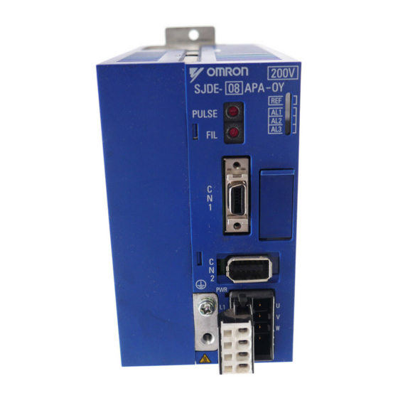
Page 13: Model Designation
1.3 Model Designation 1.3 Model Designation SJDE—02 A P A —OY JUNMA series SERVOPACK SJDE Applicable servomotor capacity Code Output (W) Power supply voltage A: 200 VAC Interface specification P: Pulse train reference Design revision order 1.4 SERVOPACKs and Applicable Servomotors... -
Page 14: Part Names And Functions
PULS 5000 Line driver SIGN 10000 Mark + pulse sequence, 1000 Open collector Negative logic 2500 or line driver 5000 PULS Line driver SIGN 10000 Note: 1. Make settings after turning OFF the power. 2. The factory setting is 0. -
Page 15: Reference Filter Setting Rotary Switch (Fil)
Do not set 8 through F. 8 to F * 1. The factory setting is 0. If the machine vibrates, this value must be changed. * 2. If the machine vibrates when starting or stopping the machine, set a larger value. -
Page 16: Installation
SERVOPACK does not exceed 55 ° C. panel Installation near a Minimize the heat radiating from the heating unit as well as any heating unit temperature rise caused by natural convection so the temperature around the SERVOPACK does not exceed 55 ° C. -
Page 17: Installation Method
• Be sure to keep a space between adjacent SERVOPACK units if they are mounted inside the control panel so that the units can be cooled. • Do not cover the inlet or outlet parts and prevent any foreign objects, such as metalic fragment, or combustibles from entering the product. -
Page 18: Wiring
Caution for Cable • For wiring, use the specified cables. Use cables that are as short as possible. • Do not bend or apply tension to cables. The conductor of a signal cable is very thin (0.08 to 0.12 mm... -
Page 19: Other Precautions
For system safety, include a sequence so that the /S-ON signal will turn OFF when the limit switch is activated. • If the servomotor is used to drive a vertical axis, install a safety device with an alarm function to pre- vent the workpiece from falling down. Failure to observe this precaution may result in injury or dam- age to the equipment from fallen workpieces. -
Page 20: Capacity
Ground Fault NOTE The ground protection circuit is designed for ground fault inside the motor windings while the motor is running. Therefore, it may not protect the system under the following conditions. • A low-resistance ground fault occurs between the main circuit cable and connector for the servomotor. -
Page 21: Noise Prevention
Groudning: Ground to one point only. Min. grounding resistance: 100 Ω * 1. For the wires connected to the casings for installation purposes, use wires with a diameter of 3.5 mm or larger. Flat braided copper wires are recommended. * 2. Use twisted pair wires for section P. - Page 22 3.1 Precautions on Wiring Noise Filters Use noise filters to prevent any noise interference from the power-supply line. The following table lists the recommended noise filters. Recommended Noise Filters Power- SERVOPACK Model Recommended Noise Filters Supply Voltage Model Specifications Manufacturer...
- Page 23 3.1 Precautions on Wiring Filter dimensions for model R7A-FIZP105-BE Filter dimensions for model R7A-FIZP109-BE...
-
Page 24: System Configuration
Servomotors ( CNA ) Used for a regenerative unit. Regenerative unit Used if regenerative energy is high. To the control circuits of magnetic contactor * Prepare a 24-VDC power supply for the brake separately from the sequence power supply. -
Page 25: Standard Connection
3.3 Standard Connection 3.3 Standard Connection Power supply Single-phase 200 V to 230 VAC 50/60Hz Molded-case circuit breaker Surge protector Noise filter AVR1* 24 V power supply + 24V 200 V to Brake Varistor 230 VAC SERVOPACK Fuse Spark killer... -
Page 26: Installation And Wiring Conditions On Ce Marking
* Prepare a 24 VDC power supply for sequence separately from the 24 VDC power supply for brake. 3.4 Installation and Wiring Conditions on CE Marking To adapt a combination of a SJME servomotor and a SJDE SERVOPACK to EMC Directives (EN55011, group 1, class A and EN61000-6-2), the following conditions must be satisfied. -
Page 27: Attaching The Ferrite Core
A shield box, which is a closed metallic enclosure, should be used for shielding magnetic interference. The structure of the box should allow the main body, door, and cooling unit to be attached to the ground. The box opening should be as small as possible. -
Page 28: Servopacks And Applicable Peripheral Devices
Co., Ltd. GmbH * 1. Nominal value at the rated load. The specified derating is required to select the appropriate molded- case circuit breaker. * 2. Cut-off characteristics (25 ° C): 200 % two seconds min. and 700 % 0.01 seconds min. -
Page 29: Servopack Main Circuit Wire Size
75 ° C Temperature-resistant vinyl cable • Wire sizes are selected for three cables per bundle at 40 ° C ambient temperature with the rated cur- rent. • Use cables with a minimum withstand voltage of 600 V for main circuits. -
Page 30: Encoder Signal Connector
Use OYMC specified wires, or shielded twisted-pair wires. Maximum cable length 20 m Applicable wires AWG22 (0.33 mm ) and AWG26 (0.12 mm Used AWG22 for the encoder power supply and AWG26 for signal lines. φ9 mm max. Finished cable outer diameter I/O signal connector Item... -
Page 31: Wiring The Power Supply/Regenerative Unit Connector (Cna)
Tool must be purchased by the customer. • Use a standard flat-blade screwdriver (blade width of 2.5 to 3.0 mm (0.09 to 0.12 in)). Put the blade into the slot, as shown in Fig. B, and press down firmly to open the wire terminal. -
Page 32: Connector For Power Supply/Regenerative Unit (Cna)
— Note: 1. Pull lightly on the wires to confirm that they are securely connected. 2. Be sure that none of the insulating sheaths of the wires are caught in the springs. Connector for Power Supply/Regenerative Unit (CNA) Pin No. -
Page 33: Wiring The Servomotor Main Circuit Cable Connector (Cnb)
3.9 Wiring the Servomotor Main Circuit Cable Connector (CNB) Wire the connector for the servomotor main circuit cable (CNB) in the same way as the connector for the power supply/regenerative unit (CNA). Refer to the previous section for details and the procedure. -
Page 34: Servomotors With Brakes
(for relaying) Note: 1. Prepare a double-insulated 24-VDC power supply. 2. Connect the varistor in parallel with the 24-V power supply terminal and GND terminal to suppress the surge voltage resulting from the holding brake turned ON and OFF. 3. Pin numbers are given on the connector as well. - Page 35 3.9 Wiring the Servomotor Main Circuit Cable Connector (CNB) 4. If using the servomotor to drive a vertical axis, provide a circuit to turn the holding brake ON so that the movable section will not be pulled down by gravity when the power supply of the SERVO- PACK is turned OFF.
-
Page 36: Wiring The Encoder Connector (Cn2)
Separate by 300 mm or more Power Supply • Separate the encoder cable at least 300 mm from power lines (i.e., high-voltage lines such as the NOTE power supply line and servomotor main circuit cable). • Do not bundle with or run the encode cable in the same duct as power lines. -
Page 37: Wiring I/O Connectors
Damage to the cable or connectors may cause the product to stop operating or malfunction. • Separate the I/O cable at least 300 mm from power lines (i.e., high-voltage lines, such as the NOTE power supply line and servomotor main circuit cable). -
Page 38: Connection Diagram And Description For The General-Purpose Control Cables (R7A-Cpz@@@S) Supplied By Omron Company
A General-purpose Control Cable connects to the Servo Driver's Control I/O Connector (CN1). There is no connector on the controller end. Wire a connector to match the controller if you are connecting to a Position Control Unit and a compatible cable is not available, or if the drive is connected to a controller manufactured by another company. - Page 39 3.11 Wiring I/O Connectors Connector Pin Arrangement...
-
Page 40: Connection Examples Of Input Signal
75Ω /CLR ∗ Twisted-pair wires Open-collector Output Set the current limit resistors R1 through R3 so that the input current (i) will be within the following range. Input Current (i) = 7 mA to 15 mA 24VDC Power Supply SERVOPACK... -
Page 41: Connection Example Of Output Signal
3.13 Connection Example of Output Signal 3.13 Connection Example of Output Signal Set the load so that the output current (i) will fall within 50 mA or less. Photocoupler output (Per output signal) Max. voltage: 30VDC Max. current: 50m ADC... -
Page 42: Emg Sequence
3.14 EMG Sequence WARNING • Make the emergency stop circuit to turn OFF the Servo ON signal as well as the main circuit power supply when the EMG (emergency stop) signal turns ON. The residual voltage rotates the servomotor for a few seconds after the power supply has turned OFF, which may result in injury or damage to the equipment. -
Page 43: Explanation Of I/O Signals
ON, the motor will stop at that position. * 3. The lag time for the brake is 100 ms. Use a relay for brakes with an operating time of 30 ms or less. Note: 1. The maximum lag time from the time that the error or fault is detected until the time that the alarm signal is turned ON is 2 ms. - Page 44 (SIGN + PULS signal) SIGN t1, t2, t3 > 3μs High = Forward τ ≥ 0.65μs reference ( τ/T ) × 100 ≤ 50% PULS Maximum reference frequency: Low = Reverse reference 750 kpps (187.5 kpps for an Forward reference...
-
Page 45: Trial Operation
If the indicator is orange, turn ON the servo ON (S-ON) input signal and check that the color of the REF indicator changes from orange to green. • If the REF indicator is not orange or green, or the indicator of the Check that the color of the REF... - Page 46 • If the machine vibrates or if the positioning completed signal (/COIN) repeatedly turns ON and OFF after the servomotor stops, turn the FIL rotary switch from 0 to 1, and then to 0 again. If the machine still vibrates, gradually increase the setting on the FIL Select the FIL rotary switch from 0 to 7 until the optimum setting is reached.
-
Page 47: Troubleshooting
Contact your OYMC representative if the problem cannot be solved by the corrective actions described here. • When taking a corrective action, turn OFF the power, remove the cause of the alarm, and then turn NOTE ON the power again. - Page 48 Encoder cable wiring is incor- from the con- rect or a contact in the cable is troller. faulty. The starting torque exceeds the Reconsider and correct the maximum torque.
- Page 49 Alarm Occur- Cause Corrective Action Display Name rence Encoder Power was The encoder wiring and the con- Correct the encoder wiring. error turned ON or tact are incorrect. during servo- Noise interference occurred due Use twisted-pair or shielded motor opera-...
- Page 50 Cause Corrective Action Display Name rence Overcurr- Power was Phases U, V, and W in the ser- Check and correct the servomo- turned ON. vomotor are wired to the wrong tor wiring. terminals. The ground wire is caught on other terminals.
- Page 51 Alarm Display Alarm Occur- Cause Corrective Action Name rence SERVO- Power was The cooling fan built into the Refer to Section 6 and PACK turned ON or SERVOPACK stopped. replace the cooling fan. built-in during servo- The air inlet of the cooling Inspect the cooling fan.
-
Page 52: Troubleshooting For Malfunctions When Alarm Indicators Are Not Lit
5.2 Troubleshooting for Malfunctions when Alarm Indicators Are Not Lit 5.2 Troubleshooting for Malfunctions when Alarm Indicators Are Not Lit Troubleshooting for malfunctions that occur with the servomotor even though the alarm indicators do not light are listed below. Perform the appropriate corrective actions accordingly. - Page 53 5.2 Troubleshooting for Malfunctions when Alarm Indicators Are Not Lit Problem Cause Inspection Items Corrective Action Servomotor The wiring of the servomotor Check the order of phases U, Correct the wiring. turns for a main circuit cable and V, and W in the servomotor moment and encoder cable is incorrect.
- Page 54 5.2 Troubleshooting for Malfunctions when Alarm Indicators Are Not Lit Problem Cause Inspection Items Corrective Action Servomotor The servomotor is over- Check to see if the load is Reconsider the load condi- does not stop loaded. excessive or the servomotor...
-
Page 55: Inspections
Life depends on operation conditions. Check that there is no unusual noise or vibration. Note: 1. The life expectancy listed in the table is a reference period that may be affected by the environ- mental and operating conditions. 2. The recommended models of the replacement cooling fans are:... -
Page 56: Replacement Of Cooling Fan
6.3 Replacement of Cooling Fan WARNING • Do not open the SERVOPACK case for five minutes after the LED (PWR) is turned OFF. Residual voltage may cause electric shock. • Disconnect all power and wait at least 15 minutes before replacing the cooling fan. - Page 57 6.3 Replacement of Cooling Fan 3. Disconnect the cable of the cooling fan Pick the cable up, and then pull it out. from the fan connector on the SERVO- PACK. 4. Unscrew the cooling fan and remove it. Cooling fan Mounting screw 5.
- Page 58 SERVOPACK case and the two on the cover on the SERVOPACK one by one and pry the case off. 2. Pull the case and the cover off of the SERVOPACK. Case Cover 3. Disconnect the cable of the cooling fan from the fan connector on the SERVO- PACK.
- Page 59 6.3 Replacement of Cooling Fan 4. Remove the two mounting screws of the cooling fan. Cooling fan Mounting screws 5. Install the new cooling fan. Thread the cooling-fan cable through Diagram A the opening ( ) as shown in the dia- gram A.
- Page 60 SERVOPACK. CAUTION: Make sure that the wiring layout of the cable matches that shown in the diagram. 8. Reattach the case and cover to the SERVOPACK in their original positions. Place the cooling-fan cable as shown here.
-
Page 61: Specifications
Note: OFF for 2s when power is turned ON. Brake output signal External signal to control brakes. Turn ON to release the brake. ON if the current position is equal to the reference position ±10 Positioning completed output signal pulses.External signal to control brakes. -
Page 62: Overload Protection Characteristics
• Overload protection characteristics are the values used when the motor attached to the aluminum heatsink [250 mm × 250 mm × 6 mm (23.62 in × 23.62 in × 0.24 in)] at the ambient temperature of 40 ° C (104 ° F). Make sure to use the SERVOPACK in the recommended operating conditions. - Page 63 YASKAWA In the event that the end user of this product is to be the military and said product is to be employed in any weapons systems or the manufacture thereof, the export will fall under the relevand regulations as stipulated in the Foreign Exchange and Foreign Trade Regulations.
Need help?
Do you have a question about the SJDE-APA-OY and is the answer not in the manual?
Questions and answers