Sign In
Upload
Manuals
Brands
Omron Manuals
DC Drives
Junma ML-II SJDE-04ANA-OY
Omron Junma ML-II SJDE-04ANA-OY Manuals
Manuals and User Guides for Omron Junma ML-II SJDE-04ANA-OY. We have
2
Omron Junma ML-II SJDE-04ANA-OY manuals available for free PDF download: Manual, System Configuration
OMRON Junma ML-II SJDE-04ANA-OY Manual (170 pages)
JUNMA SJDE-**ANA-OY SERIES SERVO c
Brand:
OMRON
| Category:
DC Drives
| Size: 7.06 MB
Table of Contents
Introduction
3
Related Manuals
3
Safety Information
3
Visual Aids
3
Trademarks
3
Notes for Safe Operation
4
Table of Contents
11
1 Before Use
15
Checking Products
15
Warning Label
15
Model Designation
16
Servopacks and Applicable Servomotors
16
Part Names and Functions
17
Applicable Standards
18
North American Safety Standards (UL, CSA)
18
European Directives
18
2 Installation
19
Installation Conditions
19
Installation Method
20
3 Wiring
21
System Configuration
21
Standard Connection
22
Precautions on Wiring
23
Protection for Power Supply Line
23
Caution for Grounding
23
Caution for Cable
24
Power Loss
24
Servopacks and Applicable Peripheral Devices
24
Noise Prevention
25
Installation and Wiring Conditions on CE Marking
28
Other Precautions
29
Main Circuit Wiring
29
SERVOPACK Main Circuit Cables
29
Wiring Connector for the Power Supply/Regenerative Unit (CNA)
34
Wiring Connector for the Servomotor Main Circuit Cable (CNB)
36
Wiring the Encoder Connector (CN2)
40
Wiring the I/O Signal Connector (CN1)
41
Wiring the MECHATROLINK-II Communication Connectors (CN6A and CN6B)
43
Wiring the Personal Computer Connector (CN9)
45
Connection Examples of Input Signal
46
Connection Example of Output Signal
47
I/O Signals
48
Homing Deceleration Signal Input
48
External Latch Signal Input
48
Emergency Stop Signal Input
49
Forward/Reverse Run Prohibited Inputs (Overtravel Inputs)
51
Servo Alarm Output
52
Brake Interlock Output
52
Setting MECHATROLINK-II Communications
54
MECHATROLINK-II Communications
54
Wiring Specifications
54
Setting Communications Specifications
55
Transmission Cycle and Number of Stations
56
MECHATROLINK-II Communications Status Indicator COM LED
56
4 MECHATROLINK-II Commands
57
Lists of Commands
57
Main Commands List
57
Subcommands List
59
Main Commands
60
Communication Phases
60
No Operation (NOP: 00H)
62
Read Parameter (PRM_RD: 01H)
63
Write Parameter (PRM_WR: 02H)
64
Read ID (ID_RD: 03H)
65
Setup Device (CONFIG: 04H)
66
Read Alarm or Warning (ALM_RD: 05H)
67
Clear Alarm or Warning (ALM_CLR: 06H)
68
Start Synchronous Communication (SYNC_SET: 0DH)
69
Establish Connection (CONNECT: 0EH)
70
Release Connection (DISCONNECT: 0FH)
71
Write Stored Parameter (PPRM_WR: 1CH)
71
Set Coordinates (POS_SET: 20H)
72
Apply Brake (BRK_ON: 21H)
72
Release Brake (BRK_OFF: 22H)
74
Turn Sensor on (SENS_ON: 23H)
75
Turn Sensor off (SENS_OFF: 24H)
75
Stop Motion (HOLD: 25H)
76
Request Latch Mode (LTMOD_ON: 28H)
77
Release Latch Mode (LTMOD_OFF: 29H)
78
Status Monitoring (SMON: 30H)
79
Servo on (SV_ON: 31H)
80
Servo off (SV_OFF: 32H)
81
Interpolation Feed (INTERPOLATE: 34H)
82
Positioning (POSING: 35H)
83
Constant Speed Feed (FEED: 36H)
84
Interpolation Feeding with Position Detection (LATCH: 38H)
85
External Input Positioning (EX_POSING: 39H)
86
Homing (ZRET: 3AH)
87
Adjusting (ADJ: 3EH)
89
Subcommands
92
No Operation (NOP: 00H)
92
Read Parameter (PRM_RD: 01H)
92
Write Parameter (PRM_WR: 02H)
93
Read Alarm or Warning (ALM_RD: 05H)
93
Write Stored Parameter (PPRM_WR: 1CH)
94
Request Latch Mode (LTMOD_ON: 28H)
94
Release Latch Mode (LTMOD_OFF: 29H)
95
Status Monitoring (SMON: 30H)
95
Combination of MECHATROLINK-II Main Commands and Subcommands
96
Command Data Field
97
Latch Signal Field Specifications: LT_SGN
97
Option Field Specifications: OPTION
97
Status Field Specifications: STATUS
98
Monitor Selection and Monitor Information Field Specifications
103
Sel_Mon1/2/3/4, Monitor1/2/3/4
103
IO Monitor Field Specifications: IO_MON
105
Substatus Field Specifications: SUBSTATUS
106
Alarm/Warning Field Specifications: ALARM
107
Command and Response Timing
110
Command Data Execution Timing
110
Monitor Data Input Timing
110
Operation Sequence
111
Operation Sequence for Managing Parameters Using a
111
Controller
111
Operation Sequence for Managing Parameters
112
Using SERVOPACK
112
Operation Sequence to Turn the Servo on
113
Operation Sequence When OT (Overtravel Limit Switch) Signal Is Input
113
Operation Sequence When E-STP Signal Is Input
113
5 Trial Operation
115
6 Functions
120
Filter Setting
120
Switching Servomotor Rotation Direction
121
Electronic Gear
122
Setting the Electronic Gear
122
Position Management
125
Motion Commands
126
INTERPOLATE Related Commands
126
POSING Related Commands
126
Software Limit Function
127
Conditions Needed to Enable the Software Limit Function
127
Parameters Related Software Limit Function
127
Monitoring Software Limit
128
Latching Area
129
7 Parameters
130
Parameter Editor
130
List of Parameters
131
8 Troubleshooting
136
Alarm Displays
138
Warning Displays
140
Alarm/Warning Display and Troubleshooting
141
Alarm Display and Troubleshooting
141
Warning Display and Troubleshooting
151
Troubleshooting for Malfunction Without Alarm Display
153
9 Inspections
158
Regular Inspections
158
Part's Life Expectancy
158
Replacement of Cooling Fan
159
10 Specifications
165
Allowable Moment of Inertia
167
Overload Characteristics
168
Revision History
169
Advertisement
OMRON Junma ML-II SJDE-04ANA-OY System Configuration (4 pages)
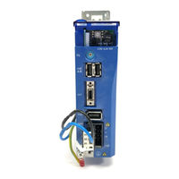
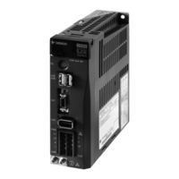
Junma ML-II servo drive
Brand:
OMRON
| Category:
Computer Hardware
| Size: 0.9 MB
Advertisement
Related Products
Omron Junma ML-II SJDE-02ANA-OY
Omron Junma ML-II SJDE-08ANA-OY
Omron JUNMA SJDE-01ANA-OY
OMRON SJDE-APA-OY
OMRON SJDE-ANA-OY
Omron SGMEV Series
Omron SGDV-02A01A-OY
Omron SGDV-02A11A-OY
Omron SGDV-04A11A-OY
Omron SGDV-20D01A-OY
Omron Categories
Blood Pressure Monitor
Controller
Accessories
Switch
Inverter
More Omron Manuals
Login
Sign In
OR
Sign in with Facebook
Sign in with Google
Upload manual
Upload from disk
Upload from URL