Table of Contents
Advertisement
Quick Links
Advertisement
Table of Contents

Related Manuals for YASKAWA PROFIBUS-DP 1000 Series


Summary of Contents for YASKAWA PROFIBUS-DP 1000 Series
- Page 1 YASKAWA AC Drive 1000-Series Option PROFIBUS-DP Technical Manual Type SI-P3 To properly use the product, read this manual thoroughly and retain for easy reference, inspection, and maintenance. Ensure the end user receives this manual. MANUAL NO. SIEP C730600 42B...
- Page 2 Yaskawa. No patent liability is assumed with respect to the use of the information contained herein. Moreover, because Yaskawa is constantly striving to improve its high-quality products, the information contained in this manual is subject to change without notice. Every precaution has been taken in the preparation of this manual.
-
Page 3: Table Of Contents
10 SPECIFICATIONS........... . 42 YASKAWA ELECTRIC SIEP C730600 42B 1000-Series Option SI-P3 Technical Manual... -
Page 4: Preface And Safety
Any warnings provided by Yaskawa must be promptly provided to the end user. Yaskawa offers an express warranty only as to the quality of its products in conforming to standards and specifications published in the Yaskawa manual. - Page 5 • The products and specifications described in this manual or the content and presentation of the manual may be changed without notice to improve the product and/or the manual. • When ordering new copies of the manual, contact a Yaskawa representative or the nearest Yaskawa sales office and provide the manual number shown on the front cover.
-
Page 6: Product Overview
PROFIBUS Decentral Periphery (PROFIBUS-DP) is one of the three PROFIBUS variants. DP is dedicated to fast data communication between systems and peripherals at a field level. This option connects a Yaskawa drive to a field network using the PROFIBUS-DP protocol. -
Page 7: Receiving
• A Phillips screwdriver (M3 metric / #1, #2 U.S. standard size) is required to install the option. • A pair of diagonal cutting pliers. • A small file or medium-grit sandpaper. Note: Tools required to prepare option cables for wiring are not listed in this manual. YASKAWA ELECTRIC SIEP C730600 42B 1000-Series Option SI-P3 Technical Manual... -
Page 8: Option Components
Control signal for repeaters (direction control) DGND Data ground (reference voltage to VP) Power supply output for bus termination (for termination resistor) – – RxD/TxD-N Receive/Transmit data; line A (green) – – YASKAWA ELECTRIC SIEP C730600 42B 1000-Series Option SI-P3 Technical Manual... - Page 9 Check the communication settings in the master. master are set incorrectly. waiting for data Sending or × × – – receiving data : Flashing / ×: Off : On / YASKAWA ELECTRIC SIEP C730600 42B 1000-Series Option SI-P3 Technical Manual...
-
Page 10: Installation Procedure
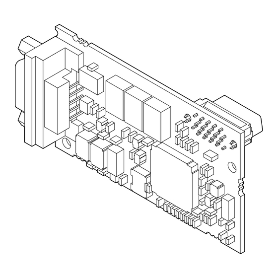
Do not use unshielded cable for control wiring. Failure to comply may cause electrical interference resulting in poor system performance. Use shielded twisted-pair wires and ground the shield to the ground terminal of the drive. YASKAWA ELECTRIC SIEP C730600 42B 1000-Series Option SI-P3 Technical Manual... - Page 11 E – LED label L – Connector CN5-A F – Terminal cover M – Connector CN5-B G – Removable tabs for wire routing N – Connector CN5-C Figure 2 Drive Components with Option YASKAWA ELECTRIC SIEP C730600 42B 1000-Series Option SI-P3 Technical Manual...
- Page 12 With the front covers and digital operator removed, apply the LED label (E) in the appropriate position on the drive top front cover (C). Figure 4 COMM Figure 4 Apply the LED Label YASKAWA ELECTRIC SIEP C730600 42B 1000-Series Option SI-P3 Technical Manual...
- Page 13 Note: There are two screw holes on the drive for use as ground terminals. When connecting more than two options, two ground wires will need to share the same drive ground terminal. YASKAWA ELECTRIC SIEP C730600 42B 1000-Series Option SI-P3 Technical Manual...
- Page 14 Incoming Cable Outgoing Cable Figure 8 PROFIBUS Cable Connection with Termination Resistors Bus termination ON = incoming and outgoing cables not connected. Bus termination OFF = incoming and outgoing cables connected. YASKAWA ELECTRIC SIEP C730600 42B 1000-Series Option SI-P3 Technical Manual...
- Page 15 <1> The drive will not meet NEMA Type 1 requirements if wiring is exposed outside the enclosure. Figure 10 Wire Routing Examples After connecting the prepared cable for the 9-pin D-sub communication connector CN5, recheck the option wire routing performed in step 6. YASKAWA ELECTRIC SIEP C730600 42B 1000-Series Option SI-P3 Technical Manual...
- Page 16 Set drive parameters in Table 8 for proper option performance. Be sure to set parameter F6-30 to a node address unique to the network. YASKAWA ELECTRIC SIEP C730600 42B 1000-Series Option SI-P3 Technical Manual...
- Page 17 5 Installation Procedure Communication Cable Specifications To ensure proper performance, Yaskawa recommends using PROFIBUS-DP-dedicated cables that fulfill the specifications in Table 6. Refer to the PROFIBUS-DP website at www.profibus.com for more information on cables. Cable Requirements Table 6 Communication Cable Requirements...
-
Page 18: Related Parameters
<1> Set b1-02 to 3 to start and stop the drive through the PROFIBUS-DP network. Set b1-01 to 3 to control the frequency reference of the drive via the PROFIBUS-DP network. YASKAWA ELECTRIC SIEP C730600 42B 1000-Series Option SI-P3 Technical Manual... - Page 19 <5> All node addresses must be unique. Node addresses 0, 1, and 2 are typically reserved for control, maintenance, and diagnostic equipment. The “Err” LED will illuminate when a value of 0 or a value greater than 125 is entered. <6> Cycle power for setting changes to take effect. YASKAWA ELECTRIC SIEP C730600 42B 1000-Series Option SI-P3 Technical Manual...
-
Page 20: Option Data And I/O Maps
Frequency Reference High Byte Motor Speed High Byte <5> Frequency Reference Low Byte Motor Speed Low Byte <5> Torque Reference High Byte Torque Reference Monitor High Byte <1> <2> <6> YASKAWA ELECTRIC SIEP C730600 42B 1000-Series Option SI-P3 Technical Manual... - Page 21 Multi-function digital input command 5 Multi-function digital input command 6 Multi-function digital input command 7 Multi-function digital input command 8 External Fault, 1: Fault (EF0) Fault Reset, 1: Fault Reset YASKAWA ELECTRIC SIEP C730600 42B 1000-Series Option SI-P3 Technical Manual...
- Page 22 <1> Unit depends on the setting of o1-03 (Digital Operator Display Scaling). When the drive is operating in V/f Control or OLV/PM, the drive output frequency becomes the input data. YASKAWA ELECTRIC SIEP C730600 42B 1000-Series Option SI-P3 Technical Manual...
- Page 23 Write: Set double number of written data items Number of data items Read: Set double number of read data items High Byte Data 1 Data word 1 <1> Low Byte YASKAWA ELECTRIC SIEP C730600 42B 1000-Series Option SI-P3 Technical Manual...
- Page 24 Data 3 Low Byte High Byte Data 4 Low Byte Reserved Handshaking Register <1> <1> Depends on the status of the previous data. <2> Depends on the status of the fault. YASKAWA ELECTRIC SIEP C730600 42B 1000-Series Option SI-P3 Technical Manual...
- Page 25 10H: SI-P3 waits for a MEMOBUS/Modbus response from the drives 11H: SI-P3 receives a MEMOBUS/Modbus response from the drives 1 to 4 Counter increases every 64 ms <1> – Not used <1> STATUS and WD are for reference. YASKAWA ELECTRIC SIEP C730600 42B 1000-Series Option SI-P3 Technical Manual...
- Page 26 Command to SI-P3 Card ⇓ Command Executed ⇓ Response Valid ⇓ Create Command ⇓ Signal New New MEMOBUS/Modbus ⇒ Message Waiting Command to SI-P3 Card ⇓ etc. Figure 12 Example of Handshaking YASKAWA ELECTRIC SIEP C730600 42B 1000-Series Option SI-P3 Technical Manual...
- Page 27 Command not executed Creates a response Creates a response message Toggles handshaking INDATA HS = register HS bit <1> Handles the response Sends to master Figure 13 MEMOBUS/Modbus Message Flowchart YASKAWA ELECTRIC SIEP C730600 42B 1000-Series Option SI-P3 Technical Manual...
-
Page 28: Parameter Process Data Object Formats
(Refer to Supported PNU on page 33 for details) SPM always 0 SPM always 0 See Response ID See Task ID When Response ID is 7, see PWE error code YASKAWA ELECTRIC SIEP C730600 42B 1000-Series Option SI-P3 Technical Manual... - Page 29 1: JOG RUN forward (Fmax/10 speed) 1: Speed agree condition 0: Stop 0: Local control 1: JOG RUN reverse (Fmax/10 speed) 1: Control from PROFIBUS 0: Local control 1: Control from PROFIBUS Always 0 Reserved YASKAWA ELECTRIC SIEP C730600 42B 1000-Series Option SI-P3 Technical Manual...
- Page 30 9.6_supp 9600 Baud 19.2_supp 19.2 kBaud 45.45_supp 45.45 kBaud 93.75_supp 93.75 kBaud 187.5_supp 187.5 kBaud 500_supp 500 kBaud 1.5M_supp 1.5 MBaud 3M_supp 3 MBaud 6M_supp 6 MBaud 12M_supp 12 MBaud YASKAWA ELECTRIC SIEP C730600 42B 1000-Series Option SI-P3 Technical Manual...
- Page 31 Maximum # of data bytes Max_User_Prm_Data_Len Ext_User_Prm_Data_Const(0) 0x40,0x01,0x00,0x01 Ext_User_Prm_Data_Ref(0) Ext_User_Prm_Data_Ref(0) Max_Diag_Data_Len Maximum diagnostic length Unit_Diag_Bit(0024) “Undervoltage Condition” Unit_Diag_Bit(0025) “Inverter Communications Error” Unit_Diag_Bit(0026) “PNU915: Illegal PNU configured” Unit_Diag_Bit(0027) “PNU916: Illegal PNU configured” YASKAWA ELECTRIC SIEP C730600 42B 1000-Series Option SI-P3 Technical Manual...
- Page 32 Module = “PPO Type 2 (No Cons.)” 0x73, 0x75 EndModule Module = “PPO Type 3 (No Cons.)” 0x71 EndModule Module = “PPO Type 4 (No Cons.)” 0x75 EndModule Module = “PPO Type 5 (No Cons.)” 0x73, 0x79 EndModule YASKAWA ELECTRIC SIEP C730600 42B 1000-Series Option SI-P3 Technical Manual...
- Page 33 Example: To read the Drive Status (ZSW) using PNU907 Command setting Data type Settings Description 638BH 6: Request parameter value from array 38BH=907 dec (PNU 907) 5th Word data of PPO type 1 YASKAWA ELECTRIC SIEP C730600 42B 1000-Series Option SI-P3 Technical Manual...
- Page 34 1: Type 1 PPO-Write 2: Type 2 PPO-Write 3: Type 3 PPO-Write 4: Type 4 PPO-Write 5: Type 5 PPO-Write – up to drive status – up to drive status YASKAWA ELECTRIC SIEP C730600 42B 1000-Series Option SI-P3 Technical Manual...
- Page 35 Baud rate (kbit/s) 19.2 93.75 187.5 1500 3000 6000 12000 PNU964 Sub-Index Description Settings Manufacturer Coding 273 dec Device type Software version Firmware Data (year) 2007 dec Firmware Data (month/day) 0220 dec YASKAWA ELECTRIC SIEP C730600 42B 1000-Series Option SI-P3 Technical Manual...
- Page 36 L3 Function Group 00–99 L4 Function Group 00–99 L5 Function Group 00–99 L6 Function Group 00–99 L7 Function Group 00–99 L8 Function Group 00–99 n1 Function Group 00–99 n2 Function Group 00–99 YASKAWA ELECTRIC SIEP C730600 42B 1000-Series Option SI-P3 Technical Manual...
- Page 37 0020H MEMOBUS/Modbus # 0021H MEMOBUS/Modbus # 0022H MEMOBUS/Modbus # 0023H MEMOBUS/Modbus # 0024H MEMOBUS/Modbus # 0025H MEMOBUS/Modbus # 0026H MEMOBUS/Modbus # 0027H MEMOBUS/Modbus # 0028H MEMOBUS/Modbus # 0029H MEMOBUS/Modbus # YASKAWA ELECTRIC SIEP C730600 42B 1000-Series Option SI-P3 Technical Manual...
- Page 38 Master command – up to Master command Response Data type Settings Description 4029H 4: Transfer parameter value (array word) 29H = 41 (d1 parameter) d1-17 258H d1-17 value YASKAWA ELECTRIC SIEP C730600 42B 1000-Series Option SI-P3 Technical Manual...
- Page 39 Master command – up to Master command Response Data type Settings Description 112CH 1: Transfer parameter value (word) 12CH = 300 – up to drive status – up to drive status YASKAWA ELECTRIC SIEP C730600 42B 1000-Series Option SI-P3 Technical Manual...
-
Page 40: Troubleshooting
• If a magnetic contactor is the noise source, install a surge absorber to the contactor coil. A data error occurred due to noise. • Use cables recommended by Yaskawa or another type of shielded line. Ground the shield on the controller side and on the option side. - Page 41 Remove any ground shorts and reconnect loose wires. properly. Master-side programming error. Check communications at start-up and correct programming errors. Perform a self-diagnostics check and replace the drive if the fault Damaged communication circuitry. continues to occur. YASKAWA ELECTRIC SIEP C730600 42B 1000-Series Option SI-P3 Technical Manual...
-
Page 42: Specifications
-20 °C to +60 °C (-4 °F to 140 °F) allowed for short-term transport of the product Storage Temperature Area of Use Indoor (free of corrosive gas, airborne particles, etc.) Altitude 1000 m (3280 ft.) or lower YASKAWA ELECTRIC SIEP C730600 42B 1000-Series Option SI-P3 Technical Manual... - Page 43 Section Revised Content Number July 2010 Back cover Revision: Address Entire document Edited for procedural clarity and readability. July 2010 Back cover Revision: Address − − August 2008 First Edition YASKAWA ELECTRIC SIEP C730600 42B 1000-Series Option SI-P3 Technical Manual...
- Page 44 Phone: 81-3-5402-4502 Fax: 81-3-5402-4580 http://www.yaskawa.co.jp YASKAWA AMERICA, INC. 2121 Norman Drive South, Waukegan, IL 60085, U.S.A. Phone: (800) YASKAWA (927-5292) or 1-847-887-7000 Fax: 1-847-887-7310 http://www.yaskawa.com YASKAWA ELÉTRICO DO BRASIL LTDA. Avenda Fagundes Filho, 620 Bairro Saude, São Paulo, SP04304-000, Brasil Phone: 55-11-3585-1100 Fax: 55-11-5581-8795 http://www.yaskawa.com.br...
Need help?
Do you have a question about the PROFIBUS-DP 1000 Series and is the answer not in the manual?
Questions and answers