YASKAWA A1000 Product Replacement Manual
Hide thumbs
Also See for A1000:
- Installation manual ,
- Technical manual (628 pages) ,
- Quick start manual (358 pages)
Table of Contents
Advertisement
Quick Links
A1000
for crane
1. Applicable Models ································································································2
2. Replacement Checklist ·························································································4
3. Terminal Compatibility Chart ·················································································6
3-1. Main Circuit Terminals ····················································································6
3-2. Control Circuit Terminals, Signal Levels ··························································· 12
3-3. Communication Circuit Terminals···································································· 15
3-4. Terminal Sizes and Wire Gauge ····································································· 16
4. Dimensions and Installation Adapters ·································································· 29
4-1. Exterior and Mounting Dimensions·································································· 29
4-2. UL Type 1 Kit······························································································ 32
4-3. Adapters and Attachments to Match Mounting Dimensions ·································· 34
4-4. Braking Resistor Installation Attachment ·························································· 36
5. Parameter Transition Guide ················································································· 37
5-1. Parameter Setting Transition Instructions ························································· 37
5-2. Checking Modified Parameters with A1000 Verify Menu ······································ 37
5-3. Parameter Compatibility Table ······································································· 38
6. Carrier Frequency and Rated Current Derating ······················································ 40
Matching Keypad and Operator·················································································· 42
Revision History ······································································································ 43
to CR700 Product Replacement Guide
TABLE OF CONTENTS
This document covers the difference between A1000 and
CR700 for a successful retrofit. Be sure to also check any
manuals (e.g. Technical Manual, etc.) for peripheral device
VAN-V17001E<1>, Replacing A1000 crane with CR700
Yaskawa Electric
Drives Division
Page
1/44
Advertisement
Table of Contents

Related Manuals for YASKAWA A1000


Summary of Contents for YASKAWA A1000
-
Page 1: Table Of Contents
4-4. Braking Resistor Installation Attachment ·························································· 36 5. Parameter Transition Guide ················································································· 37 5-1. Parameter Setting Transition Instructions ························································· 37 5-2. Checking Modified Parameters with A1000 Verify Menu ······································ 37 5-3. Parameter Compatibility Table ······································································· 38 6. Carrier Frequency and Rated Current Derating ······················································ 40 Matching Keypad and Operator··················································································... -
Page 2: Applicable Models
CR70A2011 CIMR-AA2A0018 CR70A2014 CIMR-AA2A0021 17.5 CR70A2018 17.5 CIMR-AA2A0030 CR70A2025 CIMR-AA2A0040 CR70A2033 CIMR-AA2A0056 CR70A2047 CIMR-AA2A0069 CR70A2060 CIMR-AA2A0081 CR70A2075 CIMR-AA2A0110 CR70A2088 CIMR-AA2A0138 CR70A2115 CIMR-AA2A0169 CR70A2145 CIMR-AA2A0211 CR70A2180 CIMR-AA2A0250 CR70A2215 CIMR-AA2A0312 CR70A2283 CIMR-AA2A0360 CR70A2346 CIMR-AA2A0415 CR70A2415 VAN-V17001E<1>, Replacing A1000 crane with CR700 2/44... - Page 3 CR70A4018 CIMR-AA4A0031 CR70A4024 CIMR-AA4A0038 CR70A4031 CIMR-AA4A0044 CR70A4039 CIMR-AA4A0058 CR70A4045 CIMR-AA4A0072 CR70A4060 CIMR-AA4A0088 CR70A4075 CIMR-AA4A0103 CR70A4091 CIMR-AA4A0139 CR70A4112 CIMR-AA4A0165 CR70A4150 CIMR-AA4A0208 CR70A4180 CIMR-AA4A0250 CR70A4216 CIMR-AA4A0296 CR70A4260 CIMR-AA4A0362 CR70A4304 CIMR-AA4A0414 CR70A4371 CIMR-AA4A0515 CR70A4453 CIMR-AA4A0675 CR70A4605 VAN-V17001E<1>, Replacing A1000 crane with CR700 3/44...
-
Page 4: Replacement Checklist
Hardware Verifying Main Circuit Lines (Including Ground) Location of the main circuit and its wiring configuration differ between A1000 and CR700. If there is no room for the main circuit wiring, then rearrange the wiring, or use longer wires. Verifying Main Circuit Terminal Specifications... - Page 5 Options separate location if the drive is used in an area with a high degree of vibration. (2) If planning to use the same ERF-type braking resistor installed to A1000 in the new Others CR700 drive and the cable is too short, replace the cable with a longer one only if the wire specifications are the same.
-
Page 6: Terminal Compatibility Chart
Terminal Compatibility Chart Some terminal sizes and shapes differ between A1000 and CR700. (Refer to the table in Section 3-4) 3-1. Main Circuit Terminals • Terminal functions are the same in A1000 and CR700 although terminal shapes are different. Main circuit terminals... - Page 7 - A1000 Main Circuit Terminal Configuration - CR700 Main Circuit Terminal Configuration CR70A2003,2005,2008,2011,2014,2018, 2025,2033 CR70A4002,4003,4005,4006,4007,4009, 4015,4018 => - A1000 Main Circuit Terminal Configuration - CR700 Main Circuit Terminal Configuration CR70A2047 CR70A4024,4031 => VAN-V17001E<1>, Replacing A1000 crane with CR700 7/44...
- Page 8 - A1000 Main Circuit Terminal Configuration - CR700 Main Circuit Terminal Configuration CR70A4039 - A1000 Main Circuit Terminal Configuration - CR700 Main Circuit Terminal Configuration CR70A2060,2075 VAN-V17001E<1>, Replacing A1000 crane with CR700 8/44...
- Page 9 - A1000 Main Circuit Terminal Configuration - CR700 Main Circuit Terminal Configuration CR70A2088 CR70A2115 CR70A4045 CR70A4060 - A1000 Main Circuit Terminal Configuration - CR700 Main Circuit Terminal Configuration CR70A4075 CR70A4091 VAN-V17001E<1>, Replacing A1000 crane with CR700 9/44...
- Page 10 - A1000 Main Circuit Terminal Configuration - CR700 Main Circuit Terminal Configuration CR70A2145,2180 CR70A4112,4150 CR70A2215,2283 CR70A4180,4216,4260 * The shape of the terminals are different in 2A0250 to 0415 and 4A0208 to 0362. CR70A2346,2415 CR70A4304 VAN-V17001E<1>, Replacing A1000 crane with CR700...
- Page 11 - A1000 Main Circuit Terminal Configuration - CR700 Main Circuit Terminal Configuration CR70A4371 - A1000 Main Circuit Terminal Configuration - CR700 Main Circuit Terminal Configuration CR70A4453,4605 VAN-V17001E<1>, Replacing A1000 crane with CR700 11/44...
-
Page 12: Control Circuit Terminals, Signal Levels
3-2. Control Circuit Terminals, Signal Levels • Terminal function defaults differences between A1000 and CR700 are listed in the table below. Control circuit Signal Level terminals Name A1000 CR700 A1000 CR700 Multi-function input 1 : Forward run, : Stop) Multi-function input 2... - Page 13 *1. Use the connection diagram on the following page when transferring the SC terminal wiring from A1000 to CR700. *2. Transfer wiring from the DM+ and DM- terminals on A1000 to terminals M1 and M2 or to M3 and M4 on CR700.
- Page 14 Control I/O Connections Sinking/Sourcing Mode for Digital Inputs A1000 uses a jumper on the control board to set the sinking/sourcing mode and internal/external power supply. Meanwhile, CR700 uses terminals SN, SC, and SP. Check how the jumper is set in A1000, then make corresponding changes in CR700.
-
Page 15: Communication Circuit Terminals
- A1000 Control Circuit Terminal Configuration - CR700 Control Circuit Terminal Configuration 3-3. Serial Communication Terminals Comm. terminal Signal Level Name A1000 CR700 A1000 CR700 A1000: Communications input (+) CR700: Communications input/output (+) Differential input Differential input Photocoupler A1000: Communications input (-) -
Page 16: Terminal Sizes And Wire Gauge
1.5 - 1.7 U/T1,V/T2,W/T3 2 - 14 Slot (-) CR700 CR70A2025 -,+1,+2 2 - 22 2.3 - 2.5 B1,B2 2 - 5.5 1.5 - 1.7 5.5 - 8 +/- screw 2.0 - 2.5 VAN-V17001E<1>, Replacing A1000 crane with CR700 16/44... - Page 17 5 - 5.5 U/T1,V/T2,W/T3 2 - 22 (WAF: 5 mm) CR700 CR70A2060 -,+1,+2 2 - 50 B1,B2 2 - 14 Slot (-) 1.5 - 1.7 8 - 22 +/- screw 5.4 - 6.0 VAN-V17001E<1>, Replacing A1000 crane with CR700 17/44...
- Page 18 22 - 60 Hex socket CR700 CR70A2115 -,+1 30 - 80 10 - 12 (WAF: 6 mm) B1,B2 8 - 30 Minus (-) 3 - 3.5 Hexagon bolt 22 - 38 5.4 – 6.0 VAN-V17001E<1>, Replacing A1000 crane with CR700 18/44...
- Page 19 32 - 40 R/L1,S/L2,T/L3 22 - 100x2P U/T1,V/T2,W/T3 22 - 100x2P Hexagon bolt and Nut -,+1 30 - 125x2P CR700 CR70A2215 22 - 60x2P Hexagon bolt 22 - 200 18 - 23 with slot VAN-V17001E<1>, Replacing A1000 crane with CR700 19/44...
- Page 20 32 - 40 R/L1,S/L2,T/L3 60 - 125x2P U/T1,V/T2,W/T3 60 - 125x2P Hexagon bolt and Nut -,+1 100 - 150x2P CR700 CR70A2415 38 - 150x2P Hexagon bolt 60 - 200 32 - 40 with slot VAN-V17001E<1>, Replacing A1000 crane with CR700 20/44...
- Page 21 1.5 - 1.7 U/T1,V/T2,W/T3 2 - 14 Slot (-) -,+1,+2 2 - 22 2.3 - 2.5 CR700 CR70A4018 B1,B2 2 - 5.5 1.5 - 1.7 3.5 - 8 +/- screw 2.0 - 2.5 VAN-V17001E<1>, Replacing A1000 crane with CR700 21/44...
- Page 22 2 - 14 U/T1,V/T2,W/T3 2 - 14 2.3 - 2.5 Slot (-) CR700 CR70A4039 -,+1,+2 2 - 22 B1,B2 2 - 8 1.5 - 1.7 8 - 22 +/- screw 5.4 - 6.0 VAN-V17001E<1>, Replacing A1000 crane with CR700 22/44...
- Page 23 (WAF: 5 mm) Hex socket -,+1 30 - 80 10 - 12 CR700 CR70A4091 (WAF: 6 mm) B1,B2 8 - 30 Minus (-) 3 - 3.5 Hexagon bolt 14 - 38 5.4 – 6.0 VAN-V17001E<1>, Replacing A1000 crane with CR700 23/44...
- Page 24 Minus (-) R/L1,S/L2,T/L3 22 - 100x2P U/T1,V/T2,W/T3 22 - 100x2P Hexagon bolt and Nut -,+1 30 - 125x2P CR700 CR70A4180 22 - 60x2P Hexagon bolt 22 - 200 18 - 23 with slot VAN-V17001E<1>, Replacing A1000 crane with CR700 24/44...
- Page 25 Minus (-) R/L1,S/L2,T/L3 60 - 125x2P U/T1,V/T2,W/T3 60 - 125x2P Hexagon bolt and Nut CR700 CR70A4371 -,+1 100 - 150x2P 38 - 150x2P Hexagon bolt 38 - 200 32 - 40 with slot VAN-V17001E<1>, Replacing A1000 crane with CR700 25/44...
- Page 26 Minus (-) R/L1,S/L2,T/L3 60 - 125x4P R1/L11,S1/L21,T1/L31 U/T1,V/T2,W/T3 60 - 150x4P Hexagon bolt and Nut CR700 CR70A4605 -,+1 80 - 150x4P 30 - 125x4P Hexagon bolt 60 - 150 32 - 40 with slot VAN-V17001E<1>, Replacing A1000 crane with CR700 26/44...
- Page 27 - Secure wires in the wiring section so that pressure is not applied to the terminal blocks. - After connecting the wires, gently pull on the wires to check that they do not pull out. - Regularly tighten any loose terminal block screws to their specified tightening torques VAN-V17001E<1>, Replacing A1000 crane with CR700 27/44...
- Page 28 D: When crimp ferrules are not used, remove approximately 5.5 mm of the covering at the tip. E: Blade width of 2.5 mm or less F: Blade depth of 0.4 mm or less VAN-V17001E<1>, Replacing A1000 crane with CR700 28/44...
-
Page 29: Dimensions And Installation Adapters
Exterior and Mounting Dimensions Installation holes are not the same in A1000 and CR700. The standard model A1000 (200/400V 22kW or less) is compliant for a wall-mount enclosure, while the standard model CR700 has an open-chassis design (IP20). An option is required to install CR700 in a wall-mount enclosure. - Page 30 Refer to the table below for exterior and mounting dimensions. The table below is shown with the type of A1000 and the 4 digits of CR700 catalog code. Open Type Enclosure (IP20) Note: A1000 with the following capacity (HD rating 18.5kW or less, ND rating 22kW or less) is IP00.
- Page 31 4180 0250 4216 1168 0296 4260 0362 4304 1045 Note: A1000 which capacity is stated below does not correspond to enclosed wall-mounted type (UL Type1). - CIMR-AA2A0415 and above - CIMR-AA4A0414 and above VAN-V17001E<1>, Replacing A1000 crane with CR700 31/44...
-
Page 32: Ul Type 1 Kit
900-192-121-002 Three- CR70A2047 (100-202-327) phase 900-192-121-003 200 V CR70A2060 (100-202-328) class 900-192-121-004 CR70A2075 (100-202-329) 900-192-121-005 CR70A2088 (100-202-330) 900-192-121-006 CR70A2115 (100-208-526) 900-192-121-007 CR70A2145 (100-208-527) 900-192-121-008 CR70A2180 (100-208-528) CR70A2215 900-192-121-009 (100-208-529) CR70A2283 900-192-121-010 CR70A2346 (100-213-136) VAN-V17001E<1>, Replacing A1000 crane with CR700 32/44... - Page 33 CR70A4018 CR70A4024 900-192-121-002 (100-202-327) CR70A4031 Three- phase CR70A4039 400 V 900-192-121-003 class (100-202-328) CR70A4045 900-192-121-005 CR70A4060 (100-202-330) CR70A4075 900-192-121-006 (100-208-526) CR70A4091 CR70A4112 900-192-121-007 (100-208-527) CR70A4150 CR70A4180 900-192-121-009 CR70A4216 (100-208-549) CR70A4260 900-192-121-010 CR70A4304 (100-213-136) VAN-V17001E<1>, Replacing A1000 crane with CR700 33/44...
-
Page 34: Adapters And Attachments To Match Mounting Dimensions
CR700 has a larger depth than A1000. The attachment makes it possible to mount CR700 using the same mounting holes as A1000. First mount the installation attachment to the holes that A1000 was using, and then mount CR700 to the attachment. - Page 35 1045 Note: Standard vibration tolerance specifications may not be guaranteed if an installation attachment is used. Yaskawa recommends installing the device directly to the drive in an area with a high degree of vibration. VAN-V17001E<1>, Replacing A1000 crane with CR700...
-
Page 36: Braking Resistor Installation Attachment
Class Note: Use of the braking resistor installation attachment may void certain vibration and shock requirements. Yaskawa recommends installing the braking resistor in a separate location if the drive is used in an area with a high degree of vibration. -
Page 37: Parameter Transition Guide
2) Set E: motor parameter setting (changed value) for A1000 to CR700. 3) Perform Line-to-Line Resistance (T1-02 = 2). 4) Set E: parameter setting (changed value) other than motor parameter for A1000 to CR700 according to Parameter Compatibility Table in 5-3. -
Page 38: Parameter Compatibility Table
Note: The parameter number for terminals P1 and P2 is different in CR700. - H2-02 in A1000 matches H2-04 in CR700. - H2-03 in A1000 matches H2-05 in CR700. The following parameters have a different setting range or default setting in A1000 and CR700. A1000 CR700... - Page 39 0.1 - 1000.0 Hz Minimum Frequency At the time of the 0.00 – 10.00 reverse, Speed S2-04 0.00 1.00 0.00 – 10.00 *Overwrites the value set to Feedback Detection n2-06. Restraint (AFR) Gain VAN-V17001E<1>, Replacing A1000 crane with CR700 39/44...
-
Page 40: Carrier Frequency And Rated Current Derating
Drive capacity may also make a difference in derating between A1000 and CR700. In the case of CR700 has a rated current lower than A1000 (see text highlighted in yellow in the table below), either the carrier frequency should be lowered, or a larger capacity CR700 should be selected. - Page 41 182.0 4A0362 304.0 304.0 249.3 212.8 4304 304.0 304.0 249.3 212.8 4A0414 370.0 370.0 303.4 259.0 4371 371.0 371.0 304.2 259.7 4A0515 450.0 375.0 4453 453.0 378.3 4A0675 605.0 504.0 4605 605.0 505.2 VAN-V17001E<1>, Replacing A1000 crane with CR700 41/44...
-
Page 42: Matching Keypad And Operator
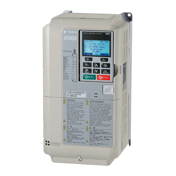
- CR700 keypad (LCD keypad comes standard) * LED keypad also available Displays several lines of text at the same time. - A1000 digital operator (LED operator comes standard) Uses up to 5 letters to display the frequency and parameter number. - Page 43 VAN-V17001E<1>, Replacing A1000 crane with CR700 43/44...
-
Page 44: Revision History
Revision History Revision No. Date Description of Change First edition 2017.09.20 First edition Corrected the "5-1. Parameter Setting Transition Instructions" (3) in the <1> 2018.07.18 chapter 5 on page 37. VAN-V17001E<1>, Replacing A1000 crane with CR700 44/44...
Need help?
Do you have a question about the A1000 and is the answer not in the manual?
Questions and answers