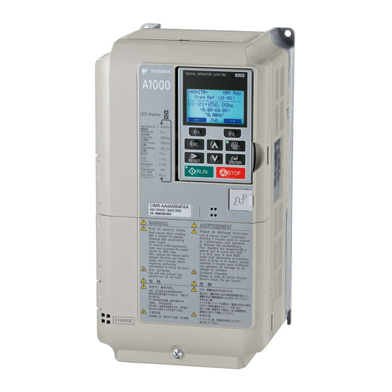
YASKAWA A1000 Manual
Ac drive
Hide thumbs
Also See for A1000:
- Installation manual ,
- Technical manual (628 pages) ,
- Quick start manual (358 pages)
Advertisement
Quick Links
YASKAWA AC Drive - A1000
Spindle Orientation
Custom Software Supplement
Software Number: VSA91009
Drive Models: 200 V Class, CIMR-AU2A0004
400 V Class, CIMR-AU4A0002
To properly use the product, read this manual thoroughly and retain
for easy reference, inspection, and maintenance. Ensure the end user
receives this manual.
MANUAL NO. TM.A1000SW.063
□
□
□
A
-063 to CIMR-AU2A0415
□
□
-063 to CIMR-AU4A0250
A
□
□
A
-063
□
□
-063
A
Advertisement

Related Manuals for YASKAWA A1000


Summary of Contents for YASKAWA A1000
- Page 1 YASKAWA AC Drive - A1000 Spindle Orientation Custom Software Supplement □ Software Number: VSA91009 □ □ □ □ Drive Models: 200 V Class, CIMR-AU2A0004 -063 to CIMR-AU2A0415 -063 □ □ □ □ 400 V Class, CIMR-AU4A0002 -063 to CIMR-AU4A0250 -063 To properly use the product, read this manual thoroughly and retain for easy reference, inspection, and maintenance.
- Page 2 YASKAWA TM.A1000SW.063 Spindle Orientation A1000 Custom Software Supplement...
- Page 3 Yaskawa. No patent liability is assumed with respect to the use of the information contained herein. Moreover, because Yaskawa is constantly striving to improve its high-quality products, the information contained in this manual is subject to change without notice.
- Page 4 This Page Intentionally Blank YASKAWA TM.A1000SW.063 Spindle Orientation A1000 Custom Software Supplement...
- Page 5 Manual No: TM.A1000SW.063 SUPPLEMENT Read this manual first. This supplement is an addendum to the A1000 Quick Start Guide and Technical Manual. It lists the effects of this custom software on the parameters in the drive and function descriptions in the manual.
- Page 6 Basic Concepts and Principles This orientation software allows an A1000 drive to repeatedly stop a machine at a certain point in its rotational cycle. This is accomplished by means of an orientation encoder directly coupled to the machine part to be positioned. A simple example is to think of the hands on a clock.
- Page 7 • Only two Auto-Tuning Mode Selections are available, 0:Rotational Auto-Tuning and 2:Stationary Auto-Tuning for Line-to-Line Resistance. Deleted Functions Certain functions in the standard software of A1000 are deleted in this Orientation software. Deleted functions are listed Table Table 2 Deleted Functions Function Name...
- Page 8 Selection 0 to 1 – – – Y– – N 1: CN5-B Mtr2 PG Port Sel Note: This parameter is available without a digital input H1-0 programmed to 16h (Motor 2 Select). YASKAWA TM.A1000SW.063 Spindle Orientation A1000 Custom Software Supplement...
- Page 9 Sets the hysteresis width of Control Mode Switch. S2-02 692h Bandwidth Increase if shock occurs during Control Mode 2 to 100 Hz – – – Y– – N HF CtrlMode SwBW switching. YASKAWA TM.A1000SW.063 Spindle Orientation A1000 Custom Software Supplement...
- Page 10 Sets the upper limit for the Slip Compensation at S2-17 69Fh Compensation Limit Hi-Speed Function for Motor 2 as a percentage of 0 to 250% – – – Y– – N HF SlipComp Lim2 the motor rated slip (E4-02). YASKAWA TM.A1000SW.063 Spindle Orientation A1000 Custom Software Supplement...
- Page 11 P1-02 and the desired orientation 0 to 100% – – – Y– – N Orient Comp Dist offset. This distance is expressed as a percentage of the active encoder PPR (e.g. F1-01 x P1-09). YASKAWA TM.A1000SW.063 Spindle Orientation A1000 Custom Software Supplement...
- Page 12 P2-05 060Eh 0 to 65535 Cnts – – – Y– – N Marker Offset 4 pulse. Refer to Orient Position Offset Selection on page Note: Counts = Encoder PPR x 4. YASKAWA TM.A1000SW.063 Spindle Orientation A1000 Custom Software Supplement...
- Page 13 Function Group Digital Operator Display Spindle Orient Group Spindle Orient Table 7 Modified Function Text Function Name Function No. Digital Operator Display High Frequency Control HighFreq Control Control Mode Switchover Ctrl Mode Switch YASKAWA TM.A1000SW.063 Spindle Orientation A1000 Custom Software Supplement...
- Page 14 Closed: Causes the drive to run in the forward direction and orient the motor to the current orientation position offset from the marker pulse. Refer to – – – Y– – N Function Description on page YASKAWA TM.A1000SW.063 Spindle Orientation A1000 Custom Software Supplement...
- Page 15 F1-31 sets Encoder PPR. If an Indirect input is activated and the frequency reference is less Drive configuration is used, Orientation encoder than the P1-01 Orient Speed. PPR is multiplied by the active gear ratio. YASKAWA TM.A1000SW.063 Spindle Orientation A1000 Custom Software Supplement...
- Page 16 F1-01 (F1-31 for encoders hooked up to option PG-B3: F1-01 × S2-01 x 2/E2-04 > 50 kHz Switch Freq Err cards in port CN5-B). PG-X3: F1-01 × S2-01 x 2/E2-04 >300 kHz <0Ch> YASKAWA TM.A1000SW.063 Spindle Orientation A1000 Custom Software Supplement...
- Page 17 Frequency Reference (determined by b1-01) Control Mode Switchover Control Mode Switchover Decel Time Bandwidth (S2-02) Frequency (S2-01) (C1-0X) Frequency [(S2-01) ‒ (S2-02)] must be greater than P1-01 or Orient Speed Accel Time OPE12 error will occur. (P1-01) (C1-0X) Machine Speed (Hz) ORT Dec Time Creep Speed (P1-12) (P1-02) Orient Complete (H2-0X = 40h) Figure 2 Orient Operation with High Frequency Switchover YASKAWA TM.A1000SW.063 Spindle Orientation A1000 Custom Software Supplement...
- Page 18 Area A includes deceleration to the P1-02 Creep Speed. Area B represents locating the marker. Area C represents the final approach of the spindle once it has reached the desired offset. Each area is described in more detail in the following sections. YASKAWA TM.A1000SW.063 Spindle Orientation A1000 Custom Software Supplement...
- Page 19 P1-02, the drive runs at the P1-04 speed while within the creep distance. Within the creep distance, the drive acceleration and deceleration times are also set to zero. This allows the drive to respond appropriately to the position error without being influenced by the C1-0 accel/decel times. YASKAWA TM.A1000SW.063 Spindle Orientation A1000 Custom Software Supplement...
- Page 20 CMD FWD or 82h Orient CMD REV digital inputs is closed. Separate run commands are not required to perform an orient from stop, as the 81h and 82h digital inputs provide their own run command to the drive. YASKAWA TM.A1000SW.063 Spindle Orientation A1000 Custom Software Supplement...
- Page 21 ORT Set Time (P1-07) Orient Complete (H2-0X = 40h) Figure 6 Orient Profile from Stop Note: If an 81h Orient CMD FWD or 82h Orient CMD REV digital input is removed and reapplied while the Orient Complete output YASKAWA TM.A1000SW.063 Spindle Orientation A1000 Custom Software Supplement...
- Page 22 (P1-02) Machine Speed (Hz) Orient Comp Dist (P1-09) Rotation due to Creep Distance External Influence Accel Time (P1-03) (C1-0X) Z Marker Pulse ORT Set Window (P1-05) ORT Rst Window (P1-06) A/B Pulse Count (Equivalent to Shaft Angle) Orient Complete ORT Set Time (P1-07) (H2-0X = 40h) Figure 7 Orient from Stop Including Marker Pulse at P1-02 YASKAWA TM.A1000SW.063 Spindle Orientation A1000 Custom Software Supplement...
- Page 23 This gear ratio may be changed by modifying parameters P2-06, P2-07, and P2-08, and then selecting the gear ratio using Gear Ratio Select digital inputs 86h and 87h. If neither of the digital inputs 86h or 87h is programmed, P2-06 is the active gear ratio. YASKAWA TM.A1000SW.063 Spindle Orientation A1000 Custom Software Supplement...
- Page 24 Rising Edge PNP N.C. Prox P1-16 = 1 Forward Rotation Channel Typical Encoder Channel P1-13 = 0 PNP N.O. Proximity Sensor Channel Figure 9 Comparison of Encoder and Proximity Sensor Marker Pulses YASKAWA TM.A1000SW.063 Spindle Orientation A1000 Custom Software Supplement...
- Page 25 If the state of the orient position offset digital inputs changes during orientation, the selection is not active until the orient digital inputs are removed. One additional digital input is available only during sequential selection: YASKAWA TM.A1000SW.063 Spindle Orientation A1000 Custom Software Supplement...
- Page 26 0 up to the number of (F1-01 x 4) encoder counts if CN5-C is the orientation encoder card, or the number of (F1-31 x 4) encoder counts if the orientation encoder card is CN5-B. Offsets which are specified as greater than one revolution are normalized to the encoder PPR. YASKAWA TM.A1000SW.063 Spindle Orientation A1000 Custom Software Supplement...
- Page 27 P1-01 Orient Speed. Once the drive enters Zero Servo Control, the P2-11 ASR gain setting is ramped to the P2-12 (ASR P Gain 4) setting over the time specified by parameter P2-13 (ASR I Time 4). YASKAWA TM.A1000SW.063 Spindle Orientation A1000 Custom Software Supplement...
- Page 28 +/- P1-06 counts of the Marker Offset, which is the light grey Orientation Reset Window in Figure Figure 12 Orient Position Orient Set Window Orient Reset Window Motor Shaft Figure 12 Orientation Set and Reset Windows YASKAWA TM.A1000SW.063 Spindle Orientation A1000 Custom Software Supplement...
- Page 29 For best noise immunity, locate the resistor network at the sensor, not at the encoder feedback card. Please note that the sensor must be able to handle at least 22 mA of current draw. For exact application wiring, consult Yaskawa Application Engineering with the exact sensor specifications. Figure 13 Common 12VDC +/- 5% ...
- Page 30 A1 Input (0 to +/- 10VDC) Speed Reference 2kΩ A2 Input A3 Input AC Common -V Supply (-10.5VDC) CN5-B Position Encoder Fault Shielded Twisted Pair H2-0X = 40h: PG Power Orient Complete PG GND H2-0X = 41h: Note: An external power supply may be Home Position required. The PG-X3 has a 200mA power supply. Check the rated current of both encoders. Figure 15 Wiring of Drive for Application Examples YASKAWA TM.A1000SW.063 Spindle Orientation A1000 Custom Software Supplement...
- Page 31 Offset & Gear 偏置和齿轮比 MarkerOffset Sel 零位脉冲偏置选择 0: Digital Input 0: 数字输入 P2-01 1: Sequential 1: 顺控选择 2: Modbus COM 2:modbus 通信 P2-02 Marker Offset 1 零位脉冲偏置 1 P2-03 Marker Offset 2 零位脉冲偏置 2 YASKAWA TM.A1000SW.063 Spindle Orientation A1000 Custom Software Supplement...
- Page 32 Chinese Display Text Spindle Orient 主轴定位监视 U7-02 Dist From Marker 零位脉冲偏移距离 U7-03 Dist From Offset 零位脉冲偏置距离 U7-02/03 Looking for C/Z 搜索零位脉冲 Alternate U7-02/03 PG Freq Limit 编码器频率限制 Alternate U7-04 Commanded Offset 指令偏置 YASKAWA TM.A1000SW.063 Spindle Orientation A1000 Custom Software Supplement...
- Page 33 原点位置 Table 22 Fault and Alarm Chinese Text Fault or Alarm English Display Text Chinese Display Text CDEV Marker Det Error 零位脉冲检测错误 OPE12 Orient Param Err 定位参数错误 OPE21 Switch Freq Err 切换频率错误 YASKAWA TM.A1000SW.063 Spindle Orientation A1000 Custom Software Supplement...
- Page 34 Date of Publication Revision Number Software Number Revised Content August 2021 VSA91009x Updated firmware number for reduced maximum frequency. November 2011 Revised pg. 19, Area B: Marker Location contents. September 2011 VSA910090 First release YASKAWA TM.A1000SW.063 Spindle Orientation A1000 Custom Software Supplement...
- Page 35 3 Revision History YASKAWA TM.A1000SW.063 Spindle Orientation A1000 Custom Software Supplement...
- Page 36 YASKAWA AC Drive - A1000 Spindle Orientation Custom Software Supplement YASKAWA AMERICA, INC. 2121 Norman Drive South, Waukegan, IL 60085, U.S.A. Phone: (800) YASKAWA (927-5292) or 1-847-887-7000 Fax: 1-847-887-7310 http://www.yaskawa.com DRIVE CENTER (INVERTER PLANT) 2-13-1, Nishimiyaichi, Yukuhashi, Fukuoka, 824-8511, Japan Phone: 81-930-25-3844 Fax: 81-930-25-4369 http://www.yaskawa.co.jp...
Need help?
Do you have a question about the A1000 and is the answer not in the manual?
Questions and answers