
Related Manuals for Nexcom NSA 7146


Summary of Contents for Nexcom NSA 7146
- Page 1 NEXCOM International Co., Ltd. Network and Communication Solutions Network Security Appliance NSA 7146 User Manual NEXCOM International Co., Ltd. www.nexcom.com Published June 2020...
-
Page 2: Table Of Contents
PCH TAP2 Header ................15 Hardware Specifications ................2 FPGA CPU1 GPIO Connectors ............15 Knowing Your NSA 7146 ................3 TPM Header ...................16 Front Panel ..................3 Block Diagram ..................17 Rear Panel ...................4 Copyright © 2019 NEXCOM International Co., Ltd. All Rights Reserved. NSA 7146 User Manual... - Page 3 Legends ....................34 BIOS Setup Utility ..................36 Main ....................36 Advanced ..................37 Platform Configuration ..............46 Socket Configuration .................51 Server Mgmt ..................74 Security .....................80 Boot ....................80 Save & Exit ..................81 Copyright © 2019 NEXCOM International Co., Ltd. All Rights Reserved. NSA 7146 User Manual...
-
Page 4: Preface
No describes how to keep the system CE compliant. part of this manual may be reproduced, copied, translated or transmitted in any form or by any means without the prior written consent from NEXCOM Declaration of Conformity International Co., Ltd. -
Page 5: Rohs Compliance
0.1% or 1,000ppm, and Polybrominated diphenyl Ethers (PBDE) < 0.1% or 1,000ppm. In order to meet the RoHS compliant directives, NEXCOM has established an engineering and manufacturing task force in to implement the introduction of green products. The task force will ensure that we follow the standard... -
Page 6: Warranty And Rma
“NEXCOM RMA Service Form” for the RMA number apply process. ▪ If RMA goods can not be repaired, NEXCOM will return it to the customer without any charge. ▪ Customers can send back the faulty products with or without accessories (manuals, cable, etc.) and any components from the card, such as CPU... - Page 7 ESD workstation. If no such station is available, you can provide some ESD protection by wearing an antistatic wrist strap and attaching it to a metal part of the computer chassis. Copyright © 2019 NEXCOM International Co., Ltd. All Rights Reserved. NSA 7146 User Manual...
-
Page 8: Safety Information
There is a danger of explosion if battery is incorrectly replaced. Replace only with the same or equivalent type recommended by the manufacturer. Discard used batteries according to the manufacturer’s instructions. viii Copyright © 2019 NEXCOM International Co., Ltd. All Rights Reserved. NSA 7146 User Manual... -
Page 9: Safety Precautions
RECOMMENDED BY THE MANUFACTURER. DISCARD USED BATTERIES ACCORDING TO THE MANUFACTURER’S INSTRUCTIONS. 10. All cautions and warnings on the equipment should be noted. Copyright © 2019 NEXCOM International Co., Ltd. All Rights Reserved. NSA 7146 User Manual... -
Page 10: Technical Support And Assistance
Preface Technical Support and Assistance Conventions Used in this Manual 1. For the most updated information of NEXCOM products, visit NEXCOM’s Warning: website at www.nexcom.com. Information about certain situations, which if not observed, can cause personal injury. This will prevent injury to yourself 2. -
Page 11: Global Service Contact Information
16F, No.250, Sec. 2, Chongde Rd., Beijing, 100094, China Beitun Dist., Tel: +86-10-5704-2680 Taichung City 406, R.O.C. Fax: +86-10-5704-2681 Tel: +886-4-2249-1179 Email: sales@nexcom.cn Fax: +886-4-2249-1172 www.nexcom.cn Email: sales@nexcom.com.tw www.nexcom.com.tw Copyright © 2019 NEXCOM International Co., Ltd. All Rights Reserved. NSA 7146 User Manual... - Page 12 Tokyo, 108-0014, Japan No. 609, Yunlin East Rd., Tel: +81-3-5419-7830 Shanghai, 200062, China Fax: +81-3-5419-7832 Tel: +86-21-5278-5868 Email: sales@nexcom-jp.com Fax: +86-21-3251-6358 www.nexcom-jp.com Email: renwang@nexcom.com.tw www.nexcom.cn Copyright © 2019 NEXCOM International Co., Ltd. All Rights Reserved. NSA 7146 User Manual...
-
Page 13: Package Contents
Preface Package Contents Before continuing, verify that the NSA 7146 package that you received is complete. Your package should have all the items listed in the following table. Item Part Number Name 19S00714600X0 NSA 7146 6023309081X00 DB9-to-RJ45 Console Cable 50311F0100X00... -
Page 14: Ordering Information
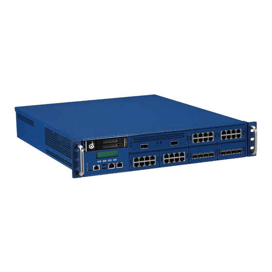
Preface Ordering Information The following information below provides ordering information for NSA 7146. Barebone NSA 7146 (P/N: TBC) 2U Intel ® Xeon ® PCH C621, with LCM, 2 swappable 2.5” HDD trays, 3 swappable system fans, 8 LAN module (NI/NX series) bays, 700W PSU... -
Page 15: Chapter 1: Product Introduction
▪ Support IPMI 2.0 ▪ Up to 8 slots for PCIe LAN modules ▪ Support Intel ready ® ® ▪ 2 x 2.5” SATA/SAS HDDs (swappable) Copyright © 2019 NEXCOM International Co., Ltd. All Rights Reserved. NSA 7146 User Manual... -
Page 16: Hardware Specifications
▪ 1 x micro USB type console port Certifications ▪ 1 x RJ45 type console port ▪ CE approval ▪ 2 x Management LAN ports ▪ FCC Class A ▪ UL Copyright © 2019 NEXCOM International Co., Ltd. All Rights Reserved. NSA 7146 User Manual... -
Page 17: Knowing Your Nsa 7146
Two LAN ports used for managing the system. Reset Button Press to restart the system. Reset indicators button LAN Modules Eight LAN module bays. Management LAN Micro ports RJ45 type console port Copyright © 2019 NEXCOM International Co., Ltd. All Rights Reserved. NSA 7146 User Manual... -
Page 18: Rear Panel
AC Power Sockets Dual redundant power supply sockets, plug an AC power cord here before turning on the system. Power VGA USB AC power switch ports sockets Copyright © 2019 NEXCOM International Co., Ltd. All Rights Reserved. NSA 7146 User Manual... -
Page 19: Chapter 2: Jumpers And Connectors
Static electricity can damage many of the electronic ▪ Use correct screws and do not over tighten screws. components. Humid environments tend to have less static electricity than Copyright © 2019 NEXCOM International Co., Ltd. All Rights Reserved. NSA 7146 User Manual... -
Page 20: Jumper Settings
(on) and open (off). Two-Pin Jumpers: Open (Left) and Short (Right) Three-Pin Jumpers: Pins 1 and 2 are Short Copyright © 2019 NEXCOM International Co., Ltd. All Rights Reserved. NSA 7146 User Manual... -
Page 21: Locations Of The Jumpers And Connectors
The figure below shows the location of the jumpers and connectors. JPWRBTN1 CON1 CPU0 CPU1 CON2 CON3 SATA1 SATA2 JP10 JP14 U101 JP15 JP17 JP18 JP16 JP19 Copyright © 2019 NEXCOM International Co., Ltd. All Rights Reserved. NSA 7146 User Manual... -
Page 22: Jumper
Chapter 2: Jumpers and Connectors Jumper RTC Clear Connector type: 1x3 3-pin header Connector location: JP8 Function 1-2 On Normal 2-3 On Clear CMOS 1-2 On: default Definition RST_RTCRST_N Copyright © 2019 NEXCOM International Co., Ltd. All Rights Reserved. NSA 7146 User Manual... -
Page 23: Internal Connectors
Connector type: 1x2 2-pin header Connector type: 2x2 4-pin header Connector location: JPWRBTN1 Connector location: CN3, CN4 and CN5 Definition Definition Definition FP_PWRBTN_R_N SYS_FAN3_TACH_P SYS_FAN3_PWM P12V Copyright © 2019 NEXCOM International Co., Ltd. All Rights Reserved. NSA 7146 User Manual... -
Page 24: Bmc Debug Header
USB 2.0 Connectors Connector type: 1x2 2-pin header Connector type: 1x6 6-pin header Connector location: JP10 Connector location: CN7 Definition Definition Definition BMC_COM_SW_N P5V_USB_P34 USB2N3_C USB2P3_C USB2N4_C USB2P4_C Copyright © 2019 NEXCOM International Co., Ltd. All Rights Reserved. NSA 7146 User Manual... -
Page 25: Internal Power Connector
Connector type: 2x8 16-pin header Connector type: 2x2 4-pin header Connector location: CON1 Connector location: CON2 Definition Definition Definition Definition P12V P12V P12V P12V P12V_V1 P12V_V1 P12V P12V P12V P12V Copyright © 2019 NEXCOM International Co., Ltd. All Rights Reserved. NSA 7146 User Manual... -
Page 26: Internal Power Connector
Connector type: 1x2 2-pin header Connector location: CON3 Connector location: J1 Definition Definition Definition +3.3V +3.3V RTC_BAT PW-OK +5VSB +12V +12V +3.3V +3.3V -12V PS-ON RES/-5V Copyright © 2019 NEXCOM International Co., Ltd. All Rights Reserved. NSA 7146 User Manual... -
Page 27: Connector
Connector type: 1x2 2-pin header Connector type: 1x16 16-pin header Connector location: J2 Connector location: J3 Definition Definition Definition VGA_VCC DDC_CLKO_B DDC_DATAO_B AVSYNCO_B AHSYNCO_B VGA_VCC DACBOA_B DACGOA_B DACROA_B Copyright © 2019 NEXCOM International Co., Ltd. All Rights Reserved. NSA 7146 User Manual... -
Page 28: Digital Power Debug Pin Header
Connector type: 1x3 3-pin header Connector type: 1x5 5-pin header Connector location: JP1 and JP2 Connector location: JP4 Definition Definition SMB_PMBUS2_STBY_LVC3_SCL JTAG_XDP_CPU_QS_GTL_TRST_N SMB_PMBUS2_STBY_LVC3_SDA JTAG_CPU1_MUX_GTL_TDO_R JTAG_MUX_CPU0_GTL_TDI JTAG_XDP_CPU_QS_GTL_TMS JTAG_XDP_CPU_GTL_TCK Copyright © 2019 NEXCOM International Co., Ltd. All Rights Reserved. NSA 7146 User Manual... -
Page 29: Pch Tap2 Header
Connector type: 2x7 14-pin header Connector location: JP5 Connector location: JP6 and JP7 Definition Definition Definition P3V3 JTAG_QS_XDP_GTL_TDO PWRGD_PVCCH_CPU1_DLY SMB_CPU1_RC_I2C1_RESET_N JTAG_XDP_QS_GTL_TDI FM_CPU1_RC_GPIO_B_4 JTAG_XDP_CPU_GTL_TMS FM_CPU1_RC_GPIO_B_3 JTAG_XDP_PCH_TCK1 FM_CPU1_RC_GPIO_B_2 FM_CPU1_RC_GPIO_B_1 FM_CPU1_RC_GPIO_B_0 Copyright © 2019 NEXCOM International Co., Ltd. All Rights Reserved. NSA 7146 User Manual... -
Page 30: Tpm Header
Chapter 2: Jumpers and Connectors TPM Header Connector type: 2x7 14-pin header Connector location: JP15 Definition Definition CLK_24M_66M_LPC0_ESPI_TPM LPC_LFRAME_N_ESPI_CS0_N_TPM LPC_LAD2_ESPI_IO2_TPM RST_R1_N_TPM LPC_LAD1_ESPI_IO1_TPM LPC_LAD3_ESPI_IO3_TPM LPC_LAD0_ESPI_IO0_TPM IRQ_LPC_SERIRQ_ESPI_CS1_N_TPM P3V3 Copyright © 2019 NEXCOM International Co., Ltd. All Rights Reserved. NSA 7146 User Manual... -
Page 31: Block Diagram
PCIe Gen2 x1 MDI_P1 MDI_P1 SATA_CFAST USB 2.0_P5/P6 I211-2 USB 2.0_P3/P4 SATA_DOM NCSI_P1 UART UART PCIe Gen1 x1 AST2400 BIOS1 CS1# CPLD BIOS2 Boot Boot Flash1 Flash2 CS2# Copyright © 2019 NEXCOM International Co., Ltd. All Rights Reserved. NSA 7146 User Manual... -
Page 32: Chapter 3: System Setup
Remove these screws and put them in a safe place for later use. 2. With the screws removed, gently slide the cover outwards and then lift up the cover to remove it. Lift here Screws on the sides Copyright © 2019 NEXCOM International Co., Ltd. All Rights Reserved. NSA 7146 User Manual... -
Page 33: Installing A Lan Module
LAN modules to prevent electric Handle shock or system damage. 1. Remove the screw on the LAN module then put them in a safe place for later use. Insert here Copyright © 2019 NEXCOM International Co., Ltd. All Rights Reserved. NSA 7146 User Manual... - Page 34 Before using Optical fiber for transferring data, make sure you have connected an approved Optical Transceiver Module. User needs to install appropriate and UL approved Laser Class I Transceivers, rated 3.3Vdc, max. 1W. Copyright © 2019 NEXCOM International Co., Ltd. All Rights Reserved. NSA 7146 User Manual...
-
Page 35: Installation Sequence Of Cpu And Memory
Socket CPU 0 Socket CPU 1 Note: The system may not boot if the first memory module is not installed in slot 1 labeled above. Copyright © 2019 NEXCOM International Co., Ltd. All Rights Reserved. NSA 7146 User Manual... -
Page 36: Assembling The 2.5" Removable Drive Bay
Assembling the 2.5” Removable Drive Bay The 2.5” removable drive bay kit contains the parts pictured below: 1. Locate the installation location for the drive bay kit. Copyright © 2019 NEXCOM International Co., Ltd. All Rights Reserved. NSA 7146 User Manual... - Page 37 Chapter 3: System Setup 2. Install the two copper standoffs to the location circled below. 3. Align the mounting holes on the base plate to the copper standoffs. Copyright © 2019 NEXCOM International Co., Ltd. All Rights Reserved. NSA 7146 User Manual...
- Page 38 4. Secure the base plate to the standoffs with screws. 5. Align the mounting holes on the drive bay enclosure to the mounting holes on the drive bay bracket. Drive Bay Bracket Drive Bay Enclosure Copyright © 2019 NEXCOM International Co., Ltd. All Rights Reserved. NSA 7146 User Manual...
- Page 39 8. Fix the drive bay bracket to the base plate with screws. 7. Repeat step 6 for securing the screws on the other side of the bracket. Copyright © 2019 NEXCOM International Co., Ltd. All Rights Reserved. NSA 7146 User Manual...
- Page 40 9. Connect the SATA data and power cables to the respective connectors on the board and the other ends of the cables to the connectors on the drive bay enclosure. Copyright © 2019 NEXCOM International Co., Ltd. All Rights Reserved. NSA 7146 User Manual...
-
Page 41: Assembling The 3.5" Removable Drive Bay
Assembling the 3.5” Removable Drive Bay The 3.5” removable drive bay kit contains the parts pictured below: 1. Locate the installation location for the drive bay kit. Copyright © 2019 NEXCOM International Co., Ltd. All Rights Reserved. NSA 7146 User Manual... - Page 42 Chapter 3: System Setup 2. Install the two copper standoffs to the location circled below. 3. Align the mounting holes on the base plate to the copper standoffs. Copyright © 2019 NEXCOM International Co., Ltd. All Rights Reserved. NSA 7146 User Manual...
- Page 43 4. Secure the base plate to the standoffs with screws. 5. Push the eject button on the HDD drive tray to release the latch. Eject button Copyright © 2019 NEXCOM International Co., Ltd. All Rights Reserved. NSA 7146 User Manual...
- Page 44 8. Repeat step 7 for securing the screws on the other side of the HDD tray. Latch Copyright © 2019 NEXCOM International Co., Ltd. All Rights Reserved. NSA 7146 User Manual...
- Page 45 9. Slide the tray back into the drive bay enclosure, and push firmly until you 10. Fix the drive bay enclosure to the base plate with screws. hear a distinctive click sound. Copyright © 2019 NEXCOM International Co., Ltd. All Rights Reserved. NSA 7146 User Manual...
- Page 46 11. Connect the SATA data and power cables to the respective connectors on the board and the other ends of the cables to the connectors on the drive bay enclosure. Copyright © 2019 NEXCOM International Co., Ltd. All Rights Reserved. NSA 7146 User Manual...
-
Page 47: Chapter 4: Bios Setup
This chapter describes how to use the BIOS setup program for NSA 7146. The settings made in the setup program affect how the computer performs. The BIOS screens provided in this chapter are for reference only and may It is important, therefore, first to try to understand all the setup options, and change if the BIOS is updated in the future. -
Page 48: Default Configuration
Powering on the computer and immediately pressing allows you to enter Setup. Load optimized default values. Saves and exits the Setup program. Press <Enter> to enter the highlighted sub-menu Copyright © 2019 NEXCOM International Co., Ltd. All Rights Reserved. NSA 7146 User Manual... - Page 49 When “” appears on the left of a particular field, it indicates that a submenu which contains additional options are available for that field. To display the submenu, move the highlight to that field and press Copyright © 2019 NEXCOM International Co., Ltd. All Rights Reserved. NSA 7146 User Manual...
-
Page 50: Bios Setup Utility
+/-: Change Opt. F1: General Help F2: Previous Values F3: Optimized Defaults F4: Save & Exit ESC: Exit Version 2.20.1275. Copyright (C) 2019 American Megatrends, Inc. Copyright © 2019 NEXCOM International Co., Ltd. All Rights Reserved. NSA 7146 User Manual... -
Page 51: Advanced
Security Device. TCG EFI protocol and INT1A interface will not be available. F2: Previous Values F3: Optimized Defaults F4: Save & Exit ESC: Exit Version 2.20.1275. Copyright (C) 2019 American Megatrends, Inc. Copyright © 2019 NEXCOM International Co., Ltd. All Rights Reserved. NSA 7146 User Manual... - Page 52 Change Settings Configuration settings for serial port 1. Selects an optimal setting for the Super IO device. Serial Port 2 Configuration Configuration settings for serial port 2. Copyright © 2019 NEXCOM International Co., Ltd. All Rights Reserved. NSA 7146 User Manual...
- Page 53 Version 2.20.1275. Copyright (C) 2019 American Megatrends, Inc. Serial Port Enables or disables the serial port. Change Settings Selects an optimal setting for the Super IO device. Copyright © 2019 NEXCOM International Co., Ltd. All Rights Reserved. NSA 7146 User Manual...
- Page 54 P12V_SCALED to SMB_TMP0 PVDDQ_ABC to PSU1_FAN Detects and displays the output voltages, temperatures and fan speeds. Detects and displays the output voltages, temperatures and fan speeds. Copyright © 2019 NEXCOM International Co., Ltd. All Rights Reserved. NSA 7146 User Manual...
- Page 55 Bits Per Second Selects the serial port transmission speed. The speed must match the other side. Long or noisy lines may require a lower speed. Copyright © 2019 NEXCOM International Co., Ltd. All Rights Reserved. NSA 7146 User Manual...
- Page 56 Selects the Putty keyboard emulation type. BME DMA Mitigation Enables or disables the function to re-enable bus master attribute during PCI enumeration for PCI bridges after SMM is locked. Copyright © 2019 NEXCOM International Co., Ltd. All Rights Reserved. NSA 7146 User Manual...
- Page 57 This is a workaround for OSs that does not support XHCI hand-off. The USB transfer time-out XHCI ownership change should be claimed by the XHCI driver. The time-out value for control, bulk, and Interrupt transfers. Copyright © 2019 NEXCOM International Co., Ltd. All Rights Reserved. NSA 7146 User Manual...
- Page 58 GA20 can be disabled using BIOS services. Always Do not allow disabling of GA20; this option is useful when any RT code is executed above 1MB. Copyright © 2019 NEXCOM International Co., Ltd. All Rights Reserved. NSA 7146 User Manual...
- Page 59 Version 2.20.1275. Copyright (C) 2019 American Megatrends, Inc. Other PCI Devices Network Stack Configures the OpROM execution policy for devices other than Network, Enables or disables UEFI network stack. Storage or Video. Copyright © 2019 NEXCOM International Co., Ltd. All Rights Reserved. NSA 7146 User Manual...
-
Page 60: Platform Configuration
PCH SATA Configuration Server ME Debug Configuration Enters the PCH SATA Configuration submenu. Enters the Server ME Debug Configuration submenu. USB Configuration Enters the USB Configuration submenu. Copyright © 2019 NEXCOM International Co., Ltd. All Rights Reserved. NSA 7146 User Manual... - Page 61 Enables or disables spread spectrum clock. Only affects external clock Configures the PCIe max read request size. generator. Pcie Pll SSC Enables or disables PCIe Phase Locked Loop for spread spectrum clock. Copyright © 2019 NEXCOM International Co., Ltd. All Rights Reserved. NSA 7146 User Manual...
- Page 62 This option configures the Serial ATA drives to use AHCI (Advanced Host Controller Interface). AHCI allows the storage driver to enable the advanced Serial ATA features which will increase storage performance. Copyright © 2019 NEXCOM International Co., Ltd. All Rights Reserved. NSA 7146 User Manual...
- Page 63 Enables or disables XHCI manual mode. Enables or disables automatic LAN Bypass function. USB Per-Connector Disable Provides the option to enable or disable each USB connector. Copyright © 2019 NEXCOM International Co., Ltd. All Rights Reserved. NSA 7146 User Manual...
- Page 64 Version 2.20.1275. Copyright (C) 2019 American Megatrends, Inc. Server ME General Configuration Override ICC Clock Settings Enters the Server ME General Configuration submenu. Enters the Override ICC Clock Settings submenu. Copyright © 2019 NEXCOM International Co., Ltd. All Rights Reserved. NSA 7146 User Manual...
-
Page 65: Socket Configuration
UPI Configuration and Memory Configuration Enters the UPI Configuration and Memory Configuration submenu. IIO Configuration and Advanced Power Management Configuration Enters the IIO Configuration and Advanced Power Management Configuration submenu. Copyright © 2019 NEXCOM International Co., Ltd. All Rights Reserved. NSA 7146 User Manual... - Page 66 Hardware Prefetcher Extended APIC Enables or disables the MLC streamer prefetcher. Enables or disables extended APIC support. L2 RFO Prefetch Disable Enables or disables L2 RFO prefetch. Copyright © 2019 NEXCOM International Co., Ltd. All Rights Reserved. NSA 7146 User Manual...
- Page 67 Provides the option to enable or disable all cores. 0 means enable all cores. FFFFFFF means disable all cores. CPU Socket 1 Configuration Processor settings for the CPU on socket 1. IOT Cfg Enables or disables IOT Cfg. Copyright © 2019 NEXCOM International Co., Ltd. All Rights Reserved. NSA 7146 User Manual...
- Page 68 Provides the option to enable or disable all cores. 0 means enable all cores. Enables or disables Isochronous support. FFFFFFF means disable all cores. Numa IOT Cfg Enables or disables Non-Uniform Memory Access support. Enables or disables IOT Cfg. Copyright © 2019 NEXCOM International Co., Ltd. All Rights Reserved. NSA 7146 User Manual...
- Page 69 Enters the UPI General Configuration submenu. Configures the link speed mode. UPI Per Socket Configuration Link Frequency Select Enters the UPI Per Socket Configuration submenu. Configures the UPI frequency. Copyright © 2019 NEXCOM International Co., Ltd. All Rights Reserved. NSA 7146 User Manual...
- Page 70 Version 2.20.1275. Copyright (C) 2019 American Megatrends, Inc. Displays information on the current UPI configuration. CPU 0 Enters the CPU 0 submenu. CPU 1 Enters the CPU 1 submenu. Copyright © 2019 NEXCOM International Co., Ltd. All Rights Reserved. NSA 7146 User Manual...
- Page 71 CPU 0 UPI Port 2 CPU 1 UPI Port 2 Enters the CPU 0 UPI Port 2 configuration submenu. Enters the CPU 1 UPI Port 2 configuration submenu. Copyright © 2019 NEXCOM International Co., Ltd. All Rights Reserved. NSA 7146 User Manual...
- Page 72 Enables or disables the UPI link. Current UPI Link Speed Current UPI Link Speed Configures the current UPI link speed. Configures the current UPI link speed. Copyright © 2019 NEXCOM International Co., Ltd. All Rights Reserved. NSA 7146 User Manual...
- Page 73 Enables or disables the UPI link. Current UPI Link Speed Current UPI Link Speed Configures the current UPI link speed. Configures the current UPI link speed. Copyright © 2019 NEXCOM International Co., Ltd. All Rights Reserved. NSA 7146 User Manual...
- Page 74 Enables or disables the UPI link. Current UPI Link Speed Current UPI Link Speed Configures the current UPI link speed. Configures the current UPI link speed. Copyright © 2019 NEXCOM International Co., Ltd. All Rights Reserved. NSA 7146 User Manual...
- Page 75 Version 2.20.1275. Copyright (C) 2019 American Megatrends, Inc. Memory Frequency Detects and displays the information on the memory installed. Configures the maximum frequency of the memory. Do not select Reserved. Copyright © 2019 NEXCOM International Co., Ltd. All Rights Reserved. NSA 7146 User Manual...
- Page 76 Enters the IIO General Configuration submenu. IIO0 Redriver Control Intel. VT for Directed I/O (VT-d) Configures the redriver options for IIO0. Enters the Intel ® VT for Directed I/O (VT-d) submenu. Copyright © 2019 NEXCOM International Co., Ltd. All Rights Reserved. NSA 7146 User Manual...
- Page 77 Configures the PCIe port maximum payload size. PCI-E Port DeEmphasis Configures the de-emphasis control for the PCIe port. PCI-E Port Max Payload Configures the PCIe port maximum payload size. Copyright © 2019 NEXCOM International Co., Ltd. All Rights Reserved. NSA 7146 User Manual...
- Page 78 Configures the de-emphasis control for the PCIe port. PCI-E Port Max Payload PCI-E Port Max Payload Configures the PCIe port maximum payload size. Configures the PCIe port maximum payload size. Copyright © 2019 NEXCOM International Co., Ltd. All Rights Reserved. NSA 7146 User Manual...
- Page 79 Configures the de-emphasis control for the PCIe port. PCI-E Port Max Payload PCI-E Port Max Payload Configures the PCIe port maximum payload size. Configures the PCIe port maximum payload size. Copyright © 2019 NEXCOM International Co., Ltd. All Rights Reserved. NSA 7146 User Manual...
- Page 80 Configures the link speed to override the max link width set by bifurcation. PCI-E Port DeEmphasis Configures the de-emphasis control for the PCIe port. PCI-E Port Max Payload Configures the PCIe port maximum payload size. Copyright © 2019 NEXCOM International Co., Ltd. All Rights Reserved. NSA 7146 User Manual...
- Page 81 Configures the de-emphasis control for the PCIe port. PCI-E Port Max Payload PCI-E Port Max Payload Configures the PCIe port maximum payload size. Configures the PCIe port maximum payload size. Copyright © 2019 NEXCOM International Co., Ltd. All Rights Reserved. NSA 7146 User Manual...
- Page 82 Configures the link speed to override the max link width set by bifurcation. PCI-E Port DeEmphasis Configures the de-emphasis control for the PCIe port. PCI-E Port Max Payload Configures the PCIe port maximum payload size. Copyright © 2019 NEXCOM International Co., Ltd. All Rights Reserved. NSA 7146 User Manual...
- Page 83 Version 2.20.1275. Copyright (C) 2019 American Megatrends, Inc. Version 2.20.1275. Copyright (C) 2019 American Megatrends, Inc. Enables or disables DMA. No Snoop Enables or disables No Snoop function for each CB device. Copyright © 2019 NEXCOM International Co., Ltd. All Rights Reserved. NSA 7146 User Manual...
- Page 84 Enables or disables DMA. No Snoop No Snoop Enables or disables No Snoop function for each CB device. Enables or disables No Snoop function for each CB device. Copyright © 2019 NEXCOM International Co., Ltd. All Rights Reserved. NSA 7146 User Manual...
- Page 85 Version 2.20.1275. Copyright (C) 2019 American Megatrends, Inc. Version 2.20.1275. Copyright (C) 2019 American Megatrends, Inc. Enables or disables DMA. No Snoop Enables or disables No Snoop function for each CB device. Copyright © 2019 NEXCOM International Co., Ltd. All Rights Reserved. NSA 7146 User Manual...
- Page 86 Virtualization Technology for Directed I/O (VT-d) by for Stack 0 to Stack 5 of Socket 0 and Socket 1. reporting the I/O device assignment to VMM through DMAR ACPI tables. Copyright © 2019 NEXCOM International Co., Ltd. All Rights Reserved. NSA 7146 User Manual...
- Page 87 SpeedStep (Pstates) Enters the CPU P State Control submenu. Enables or disables Intel ® SpeedStep technology. Hardware PM State Control Enters the Hardware PM State Control submenu. Copyright © 2019 NEXCOM International Co., Ltd. All Rights Reserved. NSA 7146 User Manual...
-
Page 88: Server Mgmt
BMC Warm Reset guidance. To perform a BMC warm reset, select this field then press <Enter>. Out of Band Mode Hardware autonomously chooses a P-state (no OS guidance). Copyright © 2019 NEXCOM International Co., Ltd. All Rights Reserved. NSA 7146 User Manual... - Page 89 Configures the options for erasing SEL. When SEL is Full Configures the action to perform when SEL is full. Log EFI Status Codes Configures the options for logging EFI status codes. Copyright © 2019 NEXCOM International Co., Ltd. All Rights Reserved. NSA 7146 User Manual...
- Page 90 Version 2.20.1275. Copyright (C) 2019 American Megatrends, Inc. Version 2.20.1275. Copyright (C) 2019 American Megatrends, Inc. IPv6 Support (LAN Channel 1) Enables or disables IPv6 support for LAN channel 1. Copyright © 2019 NEXCOM International Co., Ltd. All Rights Reserved. NSA 7146 User Manual...
- Page 91 Version 2.20.1275. Copyright (C) 2019 American Megatrends, Inc. IPv6 Support (LAN Channel 2) Displays system event log information including date, time and sensor type. Enables or disables IPv6 support for LAN channel 2. Copyright © 2019 NEXCOM International Co., Ltd. All Rights Reserved. NSA 7146 User Manual...
- Page 92 Channel No and User Privilege Limit Option to delete a user. Configures the BMC channel number and account access rights. Change User Settings Option to change user settings. Copyright © 2019 NEXCOM International Co., Ltd. All Rights Reserved. NSA 7146 User Manual...
- Page 93 Reconfigures a new password for the account. User Access Enables or disables this account. Channel No and User Privilege Limit Reconfigures the BMC channel number and account access rights. Copyright © 2019 NEXCOM International Co., Ltd. All Rights Reserved. NSA 7146 User Manual...
-
Page 94: Security
NumLock on wherein the function of the numeric keypad is the number keys. When set to Off, the function of the numeric keypad is the arrow keys. Copyright © 2019 NEXCOM International Co., Ltd. All Rights Reserved. NSA 7146 User Manual... -
Page 95: Save & Exit
Confirm by selecting Yes. Launch EFI Shell from Filesystem Device To launch EFI shell from a filesystem device, select this field and press <Enter>. Copyright © 2019 NEXCOM International Co., Ltd. All Rights Reserved. NSA 7146 User Manual...
Need help?
Do you have a question about the NSA 7146 and is the answer not in the manual?
Questions and answers