
Related Manuals for Nexcom NSA 7130


Summary of Contents for Nexcom NSA 7130
- Page 1 NEXCOM International Co., Ltd. Network and Communication Solutions Network Security Appliance NSA 7130 User Manual NEXCOM International Co., Ltd. www.nexcom.com Published January 2016...
-
Page 2: Table Of Contents
Knowing Your NSA 7130 ................3 USB 2.0 JST Connector ..............15 Front Panel ..................3 CF Module Power ................15 Rear Panel ...................4 SATA HDD Power Connector ............16 SATA DOM Power Connector ............16 Copyright © 2015 NEXCOM International Co., Ltd. All Rights Reserved. NSA 7130 User Manual... - Page 3 Entering Setup ..................32 Legends ....................32 BIOS Setup Utility ..................34 Main ....................34 Advanced ..................35 Intel RC Setup ..................43 Server Mgmt ..................62 Security .....................64 Boot ....................65 Save & Exit ..................66 Copyright © 2015 NEXCOM International Co., Ltd. All Rights Reserved. NSA 7130 User Manual...
-
Page 4: Preface
No describes how to keep the system CE compliant. part of this manual may be reproduced, copied, translated or transmitted in any form or by any means without the prior written consent from NEXCOM Declaration of Conformity International Co., Ltd. -
Page 5: Rohs Compliance
0.1% or 1,000ppm, and Polybrominated diphenyl Ethers (PBDE) < 0.1% or 1,000ppm. In order to meet the RoHS compliant directives, NEXCOM has established an engineering and manufacturing task force in to implement the introduction of green products. The task force will ensure that we follow the standard... -
Page 6: Warranty And Rma
(manuals, cable, etc.) and any components from the card, such as CPU and RAM. If the components were suspected as part of the problems, ▪ If RMA goods can not be repaired, NEXCOM will return it to the customer please note clearly which components are included. Otherwise, NEXCOM without any charge. - Page 7 ESD workstation. If no such station is available, you can provide some ESD protection by wearing an antistatic wrist strap and attaching it to a metal part of the computer chassis. Copyright © 2015 NEXCOM International Co., Ltd. All Rights Reserved. NSA 7130 User Manual...
-
Page 8: Safety Information
There is a danger of explosion if battery is incorrectly replaced. Replace only with the same or equivalent type recommended by the manufacturer. Discard used batteries according to the manufacturer’s instructions. viii Copyright © 2015 NEXCOM International Co., Ltd. All Rights Reserved. NSA 7130 User Manual... -
Page 9: Safety Precautions
RECOMMENDED BY THE MANUFACTURER. DISCARD USED BATTERIES ACCORDING TO THE MANUFACTURER’S INSTRUCTIONS. 10. All cautions and warnings on the equipment should be noted. Copyright © 2015 NEXCOM International Co., Ltd. All Rights Reserved. NSA 7130 User Manual... -
Page 10: Technical Support And Assistance
Preface Technical Support and Assistance Conventions Used in this Manual 1. For the most updated information of NEXCOM products, visit NEXCOM’s Warning: website at www.nexcom.com. Information about certain situations, which if not observed, can cause personal injury. This will prevent injury to yourself 2. -
Page 11: Global Service Contact Information
13F, No.920, Chung-Cheng Rd., ZhongHe District, Beijing, 100094, China New Taipei City, 23586, Taiwan, R.O.C. Tel: +86-10-5704-2680 Tel: +886-2-8226-7796 Fax: +86-10-5704-2681 Fax: +886-2-8226-7792 Email: sales@nexcom.cn Email: sales@nexcom.com.tw www.nexcom.cn www.nexcom.com.tw Copyright © 2015 NEXCOM International Co., Ltd. All Rights Reserved. NSA 7130 User Manual... -
Page 12: United Kingdom
Hui Yin Ming Zun Building Room 1108, Building No. 11, 599 Yunling Road, Putuo District, Shanghai, 200062, China Tel: +86-21-6125-8282 Fax: +86-21-6125-8281 Email: frankyang@nexcom.cn www.nexcom.cn Copyright © 2015 NEXCOM International Co., Ltd. All Rights Reserved. NSA 7130 User Manual... -
Page 13: Package Contents
Preface Package Contents Before continuing, verify that the NSA 7130 package that you received is complete. Your package should have all the items listed in the following table. Item Part Number Name Description 19S00713002X0 NSA 7130A ASSY 50311F0095X00 (H)Flat Head Screw Long Fei:F6#32Tx5 NYLOK NIGP... -
Page 14: Ordering Information
Preface Ordering Information The following information below provides ordering information for NSA 7130. Barebone NSK 5199R-F2 NSA 7130 (P/N: 10S00713002X0) PCIe 10GbE module with 2 SFP+ ports based on Intel 82599EB chipset ® Support Intel ® Xeon ® E5 series processors V3, 16 DDR4 memory slots,... -
Page 15: Chapter 1: Product Introduction
▪ Support DDR4 1866/2133 ECC & REG, up to 512GB ▪ 2U, 450mm depth chassis design ▪ On-board 16G LAN Copper/Fibre + 4x 10G SFP+ ▪ Two LAN Module Slots Copyright © 2015 NEXCOM International Co., Ltd. All Rights Reserved. NSA 7130 User Manual... -
Page 16: Hardware Specifications
▪ 2x USB 2.0 ports ▪ FCC Class A ▪ 1x RJ45 type Console port ▪ UL ▪ 1x Software button ▪ 2x Management LAN ports Copyright © 2015 NEXCOM International Co., Ltd. All Rights Reserved. NSA 7130 User Manual... -
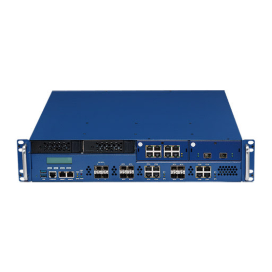
Page 17: Knowing Your Nsa 7130
Used to connect LAN network devices. console port LED Indicators Indicates the power, hard drive, and GPIO activity of the system. Bypass LEDs Indicates the status of the LAN bypass. Copyright © 2015 NEXCOM International Co., Ltd. All Rights Reserved. NSA 7130 User Manual... -
Page 18: Rear Panel
Used to connect an analog VGA monitor. AC Power Sockets Dual redundant power supply sockets, plug an AC power cord here before turning on the system. AC Power Sockets Power switch Copyright © 2015 NEXCOM International Co., Ltd. All Rights Reserved. NSA 7130 User Manual... -
Page 19: Chapter 2: Jumpers And Connectors
Static electricity can damage many of the electronic ▪ Use correct screws and do not over tighten screws. components. Humid environments tend to have less static electricity than Copyright © 2015 NEXCOM International Co., Ltd. All Rights Reserved. NSA 7130 User Manual... -
Page 20: Jumper Settings
(on) and open (off). Two-Pin Jumpers: Open (Left) and Short (Right) Three-Pin Jumpers: Pins 1 and 2 are Short Copyright © 2015 NEXCOM International Co., Ltd. All Rights Reserved. NSA 7130 User Manual... -
Page 21: Locations Of The Jumpers And Connectors
The figure below shows the location of the jumpers and connectors. FAN2 CON1 FAN1 FAN3 CON2 J8 J9 CON3 VGACONN1 JTPMSEL1 JCLRM1 JMEUP1 JMEUP2 JP10 JP11 JP12 LAN1 Copyright © 2015 NEXCOM International Co., Ltd. All Rights Reserved. NSA 7130 User Manual... -
Page 22: Jumpers
Connector location: JP12 Connector location: JTPMSEL1 Function Function RTS to CTS Enable some special commands 2-3* Disable some special 2-3 On: default 2-3* commands 2-3 On: default Copyright © 2015 NEXCOM International Co., Ltd. All Rights Reserved. NSA 7130 User Manual... -
Page 23: Rtc Clear
Connector location: JCLRM1 Connector location: JMEUP1 Function Function 1-2* No Clear CMOS 1-2* No Clear Password Clear CMOS Clear Password 1-2 On: default 1-2 On: default Copyright © 2015 NEXCOM International Co., Ltd. All Rights Reserved. NSA 7130 User Manual... -
Page 24: Me Firmware Update
Disable ME Force Update PCIE Device RST signal ME Force Update refer PCH PLTRST PCIE Device RST signal 1-2 On: default refer PCH PROCPWRGD NC: default Copyright © 2015 NEXCOM International Co., Ltd. All Rights Reserved. NSA 7130 User Manual... -
Page 25: Bmc Strap
Connector type: 1x2 2-pin header, 2.54mm Connector location: JP10 Connector location: JP11 Function Function Enable BMC System UART Controller Disable BMC BMC Debug UART Controller NC: default NC: default Copyright © 2015 NEXCOM International Co., Ltd. All Rights Reserved. NSA 7130 User Manual... -
Page 26: Fm_Pld_Debug
Chapter 2: Jumpers and Connectors FM_PLD_DEBUG Connector type: 1x2 2-pin header, 2.54mm Connector location: JP8 Function Disable CPLD Debug Mode Enable CPLD Debug Mode NC: default Copyright © 2015 NEXCOM International Co., Ltd. All Rights Reserved. NSA 7130 User Manual... -
Page 27: Connector Pin Definitions
Connector Pin Definitions External Connectors System Reset Button RJ45 Console Port Connector location: SW3 Connector location: LAN1 Definition Definition Definition SP_RTS1_R SP_DTR1_R RST_BTN_N SP_TXD1_R SP_DCD1_R SP_RXD1_R SP_DSR1_R SP_CTS1_CON Copyright © 2015 NEXCOM International Co., Ltd. All Rights Reserved. NSA 7130 User Manual... -
Page 28: Internal Connectors
Connector type: 1x6 6-pin header, 2.54mm Connector location: CN5 Connector location: JP2 Definition Definition Definition Definition SP_DCD2 SP_RXD2 P3V3_AUX SP_TXD2 SP_DTR2 JTAG_ TCK JTAG_TDO SP_DSR2 JTAG_TDI JTAG_TMS SP_RTS2 SP_CTS2 SP_RI2 Copyright © 2015 NEXCOM International Co., Ltd. All Rights Reserved. NSA 7130 User Manual... -
Page 29: Usb 2.0 Jst Connector
Connector type: 1x6 6-pin header, 2.0mm Connector type: 1x4 4-pin Wafer Connector location: J10 Connector location: CN4 Definition Definition Definition Definition USB2_L_DN2- P12V USB2_L_DP2 USB2_L_DN2- USB2_L_DP2 Copyright © 2015 NEXCOM International Co., Ltd. All Rights Reserved. NSA 7130 User Manual... -
Page 30: Sata Hdd Power Connector
SATA HDD Power Connector SATA DOM Power Connector Connector type: 1x4 4-pin header Connector type: 1x2 JST, 2-pin header Connector location: J7 Connector location: J11 Definition Definition Definition P12V Copyright © 2015 NEXCOM International Co., Ltd. All Rights Reserved. NSA 7130 User Manual... -
Page 31: System Fan Connectors
Connector type: 2x2 4-pin header Connector type: 1x4 4-pin Wafer Connector location: CN1, CN2 and FAN3 Connector location: FAN1 and FAN2 Definition Definition Definition Definition P12V P12V TACH TACH Copyright © 2015 NEXCOM International Co., Ltd. All Rights Reserved. NSA 7130 User Manual... -
Page 32: Vga Connector
Connector type: 1x4 4-pin header Connector location: VGACONN1 Connector location: CN6 Definition Definition Definition Definition DACROA_B DACGOA_B SMB_IPMB_STBY_C_DATA DACBOA_B SMB_IPMB_STBY_C_CLK P5V_AUX VGA_VCC AVSYNCO_B AHSYNCO_B AVSYNCO_B DDC_CLKO_B Copyright © 2015 NEXCOM International Co., Ltd. All Rights Reserved. NSA 7130 User Manual... -
Page 33: Pdb Connector
Definition Definition Definition A1-A9 B1-B9 A10-A18 P12V B10-B18 P12V PSU_SMB_DATA P12V P12V PSU_SMB_CLK PS_EN_PSU_N P12V P12V P12V_STBY IRQ_SML1_PMBUS_ RETURN_SENSE ALERT_N PWRGD_PS_PWROK PRESEND1 AC_FAIL_PSU 12V_REMOTE_SENSE P3V3_AUX PRESEND2 Copyright © 2015 NEXCOM International Co., Ltd. All Rights Reserved. NSA 7130 User Manual... -
Page 34: Riser Card Power Connector
D1 D2 E1 E2 F1 F2 D3 D4 E3 E4 F3 F4 Definition Definition P3V3 P3V3_AUX P3V3 P3V3_AUX P3V3 P3V3_AUX P3V3 P3V3_AUX P12V P12V P12V P12V Copyright © 2015 NEXCOM International Co., Ltd. All Rights Reserved. NSA 7130 User Manual... -
Page 35: Riser Card Signals Connector
CON2_RX_DN5 CON2_RX_DN4 PWRGD_PCH_PWROK CON2_RX_DP7 CON2_TX_DN1 CON2_TX_DN2 CON2_RX_DP6 CON2_RX_DP5 CON2_TX_DN3 CON2_TX_DN4 CON2_RX_DP4 RST_PERST1_N CON2_TX_DN5 CON2_TX_DP7 CON2_TX_DP1 CON2_TX_DP2 CON2_TX_DP3 CON2_TX_DP4 CON2_TX_DP5 CON2_TX_DN7 CON2_TX_DN0 CON2_RX_DN0 CON2_RX_DN1 CON2_RX_DN2 CON2_RX_DN3 CON2_TX_DN6 Copyright © 2015 NEXCOM International Co., Ltd. All Rights Reserved. NSA 7130 User Manual... -
Page 36: Riser Card Signals Connector
CLK_100M _DN PWRGD CON1_RX_DP7 CON1_TX_DN1 CON1_TX_DN2 CON1_RX_DP6 CON1_RX_DP5 CON1_TX_DN3 CON1_TX_DN4 CON1_RX_DP4 CLK_100M _DP CON1_TX_DN5 CON1_TX_DP7 CON1_TX_DP1 CON1_TX_DP2 CON1_TX_DP3 CON1_TX_DP4 CON1_TX_DP5 CON1_TX_DN7 CON1_TX_DN0 CON1_RX_DN0 CON1_RX_DN1 CON1_RX_DN2 CON1_RX_DN3 CON1_TX_DN6 Copyright © 2015 NEXCOM International Co., Ltd. All Rights Reserved. NSA 7130 User Manual... -
Page 37: Block Diagram
XL710 I350 I350 I350 I350 UART 1300 RGMII RTL8211D AST2300 support only By-Pass By-Pass 128MB 4x 10GbE SFP+ DDR-3 (Rear) 8x GbE RJ45/SFP 8x GbE RJ45/SFP Copyright © 2015 NEXCOM International Co., Ltd. All Rights Reserved. NSA 7130 User Manual... -
Page 38: Chapter 3: System Setup
1. Remove the screws on the chassis cover then put them in a safe place 2. Gently slide the cover outwards, then lift up the cover to remove it. for later use. Lift here Copyright © 2015 NEXCOM International Co., Ltd. All Rights Reserved. NSA 7130 User Manual... -
Page 39: Installing An External Sata Hard Drive
1. Push the eject button on the desired HDD drive bay to release the latch. 2. Grab on the latch and pull the drive tray out gently. Eject button Latch Copyright © 2015 NEXCOM International Co., Ltd. All Rights Reserved. NSA 7130 User Manual... - Page 40 4. Repeat step 3 for securing the screws on the other side of the HDD tray. Copyright © 2015 NEXCOM International Co., Ltd. All Rights Reserved. NSA 7130 User Manual...
-
Page 41: Installing A Lan Module
1. Remove the screw on the LAN module then put them in a safe place for later use. Insert here 3. Once the handle is firmly secured in position, pull the handle outwards to remove the LAN module bay. Copyright © 2015 NEXCOM International Co., Ltd. All Rights Reserved. NSA 7130 User Manual... - Page 42 User needs to install appropriate and UL approved Laser Class I Transceivers, rated 3.3Vdc, max. 1W. Connector side 5. Secure the module in place with screws, and slide the tray back into the bay. Copyright © 2015 NEXCOM International Co., Ltd. All Rights Reserved. NSA 7130 User Manual...
-
Page 43: Installing The Rackmount Rails
1. Extend the rackmount rail to its maximum length. are used to support the system in a rack cabinet. Slide here Rack ear Rack ear Fully extended rail Copyright © 2015 NEXCOM International Co., Ltd. All Rights Reserved. NSA 7130 User Manual... - Page 44 5. Reliable Earthing - Reliable earthing of rack-mounted equipment should be maintained. Particular attention should be given to supply connections other than direct connections to the branch circuit (e.g. use of power strips).” Copyright © 2015 NEXCOM International Co., Ltd. All Rights Reserved. NSA 7130 User Manual...
-
Page 45: Chapter 4: Bios Setup
This chapter describes how to use the BIOS setup program for the The settings made in the setup program affect how the computer performs. NSA 7130. The BIOS screens provided in this chapter are for reference only It is important, therefore, first to try to understand all the setup options, and and may change if the BIOS is updated in the future. -
Page 46: Default Configuration
Powering on the computer and immediately pressing allows you to Load previous values. enter Setup. Load optimized default values. Saves and resets the system. Press <Enter> to enter the highlighted sub-menu Copyright © 2015 NEXCOM International Co., Ltd. All Rights Reserved. NSA 7130 User Manual... - Page 47 When “” appears on the left of a particular field, it indicates that a submenu which contains additional options are available for that field. To display the submenu, move the highlight to that field and press Copyright © 2015 NEXCOM International Co., Ltd. All Rights Reserved. NSA 7130 User Manual...
-
Page 48: Bios Setup Utility
+/-: Change Opt. F1: General Help F2: Previous Values F3: Optimized Defaults F4: Save & Reset ESC: Exit Version 2.17.1245. Copyright (C) 2015 American Megatrends, Inc. Copyright © 2015 NEXCOM International Co., Ltd. All Rights Reserved. NSA 7130 User Manual... -
Page 49: Advanced
Enables or disables lock of legacy resources. F1: General Help F2: Previous Values F3: Optimized Defaults F4: Save & Reset ESC: Exit Version 2.17.1245. Copyright (C) 2015 American Megatrends, Inc. Copyright © 2015 NEXCOM International Co., Ltd. All Rights Reserved. NSA 7130 User Manual... - Page 50 Serial Port 1 Configuration Selects an optimal setting for the Super IO device. Configuration settings for serial port 1. Serial Port 2 Configuration Configuration settings for serial port 2. Copyright © 2015 NEXCOM International Co., Ltd. All Rights Reserved. NSA 7130 User Manual...
- Page 51 Serial PortGSIO200 Enables or disables the serial port. Console Redirection Enables or disables the console redirection. Change SettingsGSIO60 Selects an optimal setting for the Super IO device. Copyright © 2015 NEXCOM International Co., Ltd. All Rights Reserved. NSA 7130 User Manual...
- Page 52 Legacy OS. Default value is Always Enable The options are 7 and 8. which means Legacy Console Redirection is enabled for Legacy OS. Copyright © 2015 NEXCOM International Co., Ltd. All Rights Reserved. NSA 7130 User Manual...
- Page 53 Selects the maximum TLP payload size of the PCI Express devices. SR-IOV Support Extended Synch Enables or disables SR-IOV support. When this function is enabled, it allows generation of extended synchronization patterns. Copyright © 2015 NEXCOM International Co., Ltd. All Rights Reserved. NSA 7130 User Manual...
- Page 54 Upon Request GA20 can be disabled using BIOS services. Always Do not allow disabling GA20; this option is useful when any RT code is executed above 1MB. Copyright © 2015 NEXCOM International Co., Ltd. All Rights Reserved. NSA 7130 User Manual...
- Page 55 Security Device Support Enables or disables BIOS support for security device. O.S. will not show security device. TCG EFI protocol and INT1A interface will not be available. Copyright © 2015 NEXCOM International Co., Ltd. All Rights Reserved. NSA 7130 User Manual...
- Page 56 Disable Keeps USB devices available only for EFI applications. XHCI Hand-off This is a workaround for OSs that does not support XHCI hand-off. The XHCI ownership change should be claimed by the XHCI driver. Copyright © 2015 NEXCOM International Co., Ltd. All Rights Reserved. NSA 7130 User Manual...
-
Page 57: Intel Rc Setup
Enables or disables Virtual Machine Extensions. Enable SMX Enables or disables Secure Mode Extensions. MSR Lock Control Enables or disables locked MSR. Lock Chipset Locks or unlocks the chipet. Copyright © 2015 NEXCOM International Co., Ltd. All Rights Reserved. NSA 7130 User Manual... - Page 58 Configures the number of cores to enable. 0 means all cores. CPU Socket 1 Configuration IoT Cfg Cbo Bitmap Processor settings for the CPU on socket 1. Configures the bit to enable IOT/OCLA. Copyright © 2015 NEXCOM International Co., Ltd. All Rights Reserved. NSA 7130 User Manual...
- Page 59 Configures the number of cores to enable. 0 means all cores. Enables or disables power management features. IOT Cfg Cbo Bitmap Configures the bit to enable IOT/OCLA. Copyright © 2015 NEXCOM International Co., Ltd. All Rights Reserved. NSA 7130 User Manual...
- Page 60 Selects whether the BIOS or the operating system will enable energy performance BIAS tuning. Energy Performance BIAS Setting Configures the energy performance mode. Power/Performance Switch Enables or disables automatic switching between power and performance mode. Copyright © 2015 NEXCOM International Co., Ltd. All Rights Reserved. NSA 7130 User Manual...
- Page 61 Configures the DRAM running average power limit mode. Override BW_LIMIT_TF Enables or disables Override BW_LIMIT_TF. DRAM RAPL Extended Enables or disables extended range for the DRAM RAPL. Copyright © 2015 NEXCOM International Co., Ltd. All Rights Reserved. NSA 7130 User Manual...
- Page 62 If system options are in conflict, choose Topology Precedence to degrade features, or Feature Precedence to degrade topology. Link Speed Mode Configures the link speed mode. Link Frequency Select Configures the QPI frequency. Copyright © 2015 NEXCOM International Co., Ltd. All Rights Reserved. NSA 7130 User Manual...
- Page 63 Early Snoop Enables or disables Early Snoop support. Version 2.17.1245. Copyright (C) 2015 American Megatrends, Inc. QPI Debug Print Level Configures the QPI debug print level. Copyright © 2015 NEXCOM International Co., Ltd. All Rights Reserved. NSA 7130 User Manual...
- Page 64 Configures the IO resource allocation ratio. QPI configuration for CPU socket 1. MMIOL Resources Allocation Configures the MMIOL resource allocation ratio. IIO Disable Enables or disables IIO. Copyright © 2015 NEXCOM International Co., Ltd. All Rights Reserved. NSA 7130 User Manual...
- Page 65 Configures the MMIOL resource allocation ratio. Configures the DRAM maintenance test direction. IIO Disable DRAM Maintenance Test Invertion Enables or disables IIO. Configures the DRAM maintenance test invertion. Copyright © 2015 NEXCOM International Co., Ltd. All Rights Reserved. NSA 7130 User Manual...
- Page 66 +/-: Change Opt. F1: General Help F2: Previous Values F3: Optimized Defaults F4: Save & Reset ESC: Exit Version 2.17.1245. Copyright (C) 2015 American Megatrends, Inc. Copyright © 2015 NEXCOM International Co., Ltd. All Rights Reserved. NSA 7130 User Manual...
- Page 67 Configures the thermal throttling mode. The options are OLTT or CLTT mode. OLTT Peak BW % Configures the peak bandwidth for OLTT. DIMM Temp Stat Configures the DIMM temp stat. Phase Shedding Enables or disables Phase Shedding. Copyright © 2015 NEXCOM International Co., Ltd. All Rights Reserved. NSA 7130 User Manual...
- Page 68 IOU1 (IIO PCIe Port 3) Port Bifurcation settings for IOU 1. No PCIe Port Active Configures the workaround solution for ECO when the PCIe ports are not active. Copyright © 2015 NEXCOM International Co., Ltd. All Rights Reserved. NSA 7130 User Manual...
- Page 69 IOU1 (IIO PCIe Port 3) Port Bifurcation settings for IOU 1. No PCIe Port Active Configures the workaround solution for ECO when the PCIe ports are not active. Copyright © 2015 NEXCOM International Co., Ltd. All Rights Reserved. NSA 7130 User Manual...
- Page 70 Intel VT for Directed I/O Enables or disables Intel Virtualization Technology for Directed I/O (VT-d) by ® reporting the I/O device assignment to VMM through DMAR ACPI tables. Copyright © 2015 NEXCOM International Co., Ltd. All Rights Reserved. NSA 7130 User Manual...
- Page 71 DeepSx Power Policies Configures DeepSx power policies. GP27 Wake From DeepSx Enables or disables GP27 to wake from DeepSX. SMBUS Device Enables or disables SMBUS device. Copyright © 2015 NEXCOM International Co., Ltd. All Rights Reserved. NSA 7130 User Manual...
-
Page 72: Pci Express Configuration
Stop and Scream Enables or disables Intel ® Stop and Scream function. Expanded SPI TPM Tran Enables or disables SPI TPM transactions of up to 64 bytes. Copyright © 2015 NEXCOM International Co., Ltd. All Rights Reserved. NSA 7130 User Manual... - Page 73 1 to port 3, and port 5. increase storage performance. SATA Device Type Support Aggressive Link Identifies what type of SATA device is connected. Enables or disables Aggressive Link Power Management. Copyright © 2015 NEXCOM International Co., Ltd. All Rights Reserved. NSA 7130 User Manual...
-
Page 74: Usb Configuration
Enables or disables USB precondition on USB host controller and root ports for faster enumeration. xHCI Mode Configures the XHCI mode. Trunk Clock Gating Enables or disables Trunk Clock Gating. Copyright © 2015 NEXCOM International Co., Ltd. All Rights Reserved. NSA 7130 User Manual... - Page 75 Enables or disables the PCH BIOS lock feature. Host Flash Lock-Down Enable or disables Host Flash Lock-Down. GbE Flash Lock-Down Enable or disables GbE Flash Lock-Down. Copyright © 2015 NEXCOM International Co., Ltd. All Rights Reserved. NSA 7130 User Manual...
-
Page 76: Server Mgmt
Enables or disables the LAN module bypass mode after the system powers Power_OFF ByPass Mode Enables or disables the LAN module bypass mode after the system powers off. Copyright © 2015 NEXCOM International Co., Ltd. All Rights Reserved. NSA 7130 User Manual... - Page 77 BMC Warm Reset Log EFI Status Codes To perform a BMC warm reset, select this field then press <Enter>. Configures the options for logging EFI status codes. Copyright © 2015 NEXCOM International Co., Ltd. All Rights Reserved. NSA 7130 User Manual...
-
Page 78: Security
Displays system event log information including date, time and sensor type. Select to configure LAN channel parameters statically or dynamically (by BIOS or BMC). Unspecified option will not modify any BMC network parameters during BIOS phase. Copyright © 2015 NEXCOM International Co., Ltd. All Rights Reserved. NSA 7130 User Manual... -
Page 79: Boot
Option to add a user. Select this to reconfigure the administrator’s password. Delete User Option to delete a user. Change User Settings Option to change user settings. Copyright © 2015 NEXCOM International Co., Ltd. All Rights Reserved. NSA 7130 User Manual... -
Page 80: Save & Exit
NumLock on wherein the function of the numeric keypad is the number keys. When set to Off, the function of the numeric keypad is the arrow keys. Copyright © 2015 NEXCOM International Co., Ltd. All Rights Reserved. NSA 7130 User Manual... - Page 81 <Enter>. You may be prompted to confirm again before exiting. Restore Defaults To restore the BIOS to default settings, select this field then press <Enter>. A dialog box will appear. Confirm by selecting Yes. Copyright © 2015 NEXCOM International Co., Ltd. All Rights Reserved. NSA 7130 User Manual...
Need help?
Do you have a question about the NSA 7130 and is the answer not in the manual?
Questions and answers