
Related Manuals for Fuji Electric ZAF-6


Summary of Contents for Fuji Electric ZAF-6
- Page 1 Instruction Manual THERMAL CONDUCTIVITY GAS ANALYZER <THERMOMAT> TYPE: ZAF-6 INZ-TN6ZAF-E...
- Page 2 PREFACE We are grateful for your purchase of Fuji Electric’s Thermal Conductivity Gas Analyzer (Type:ZAF6). • First read this instruction manual carefully until an adequate understanding is acquired, and then proceed to installation, operation and maintenance of the gas analyzer. Wrong han- dling may cause an accident or injury.
- Page 3 CAUTION ON SAFETY First of all, read this “Caution on safety” carefully, and then use the analyzer in the correct way. • The cautionary descriptions listed here contain important information about safety, so they should DANGER is a risk of death or heavy injury. CAUTION is a possibility of medium-level trouble or slight injury or only physical damage is predictable.
- Page 4 Caution on wiring CAUTION Caution on piping DANGER If the leaking gas contains a toxic component, there is a risk of serious accident being induced. • Connect pipes correctly referring to the instruction manual. • Exhaust from the analyzer should be relieved in the atmospheric air in order that an unnecessary disconnected to cause gas leakage.
- Page 5 • If the cause of any fault cannot be determined despite reference to the instruction manual, be sure to contact your dealer or Fuji Electric’s technician in charge of adjustment. If the instrument is disassembled carelessly, you may have a shock hazard or injury.
-
Page 6: Table Of Contents
CONTENTS ........................i ....................ii ......................1 ..........2 Description of each unit ..................2 Principle of operation ..................... 3 ....................5 ................... 5 Mounting method ....................6 Piping ........................7 ........................ 9 3.4.1 Conditions of sampling gas ................9 ................... 9 3.4.3 Preparation for standard gas ................ - Page 7 ............... 22 Calibration setting ....................22 ............. 22 ................23 Alarm setting ......................26 ................26 ..................29 ..................30 6.3.1 Auto calibration ................... 30 6.3.2 Forced stop of auto calibration ..............32 Changeover of range ................... 33 Parameter setting ....................34 Maintenance mode ....................
- Page 8 1. OVERVIEW management and control of production processes. INZ-TN6ZAF-E...
-
Page 9: Description Of Each Unit
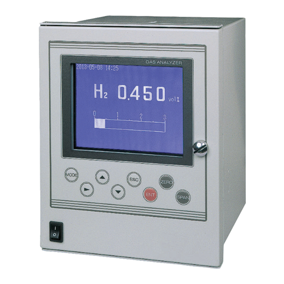
2. NAME AND DESCRIPTION OF EACH PART 2.1 Description of each unit GAS ANALYZER MODE ZERO SPAN (1) Power switch Front view Side view (2) Display and operation panel INLET (3) Sampling gas inlet (6) Terminal block (option) OUTLET 1 2 3 4 5 (4) Sampling gas outlet (5) Purge gas inlet Rear view... -
Page 10: Principle Of Operation
2.2 Principle of operation metal block. thermal conductivity of sample gas changes, temperature of the platinum changes to vary its Therefore, the Wheatstone bridge generates a voltage signal depending on kinds and concentration of the sample gas. Table 2-1 lists thermal conductivities of typical gas components, and Table 2-2 summarizes gas analyzer. - Page 11 Table 2-2 Relative Thermal Conductivities of Typical Gas Components × Type of gas components Type of gas components Ammonia 90.7 Acethylene 77.7 Methane Argon 68.5 Nitrous oxide Nitrogen 100.3 Carbonic acid gas Nitrogen monoxide 100.2 53.8 34.4 Carbon monoxide Chlorine 32.3 Fig.
- Page 12 3. INSTALLATION DANGER CAUTION • and fall to cause an injury. • 3.1 Selection of installation site substances. If such a place cannot be found, a roof or cover should be prepared for protection. (2) A vibration-free place Installation category : II Pollution Degree INZ-TN6ZAF-E...
-
Page 13: Mounting Method
3.2 Mounting method Mounting bracket Mounting (24) panel GAS ANALYZER MODE ZERO SPAN Mounting bracket (43) Panel cutout dimenssion INLET OUTLET 1 2 3 4 5 Note) Insert the analyzer into the panel cutout and fix the fittings on the analyzer from the rear panel. -
Page 14: Piping
3.3 Piping DANGER In piping, the following precautions should be observed. Wrong piping may cause gas leakage. If the leaking gas contains a toxic component, there is a risk of serious accident being induced. • Connect pipes correctly referring to the instruction manual. •... - Page 15 INLET Sampling gas inlet OUTLET Sampling gas outlet 1 2 3 4 5 Purge gas inlet Fig. 3-1 Piping Connect the pipe so that the gas may escape through the gas outlet into the atmo- sphere or equivalent. Purge gas inlet It is used for purging the inside of the total gas analyzer.
-
Page 16: Conditions Of Sampling Gas
3.4 Sampling 3.4.1 Conditions of sampling gas (4) If a large amount of highly corrosive gas such as Cl hot gas directly into the analyzer. 3.4.2 3.4.3 Preparation for standard gas Zero gas Concentration beyond 100% is inapplicable. 3.4.4 Purging of instrument inside (1) A combustible gas component is contained in sample gas. - Page 17 Analyzer (ZAF) Membrane Flow meter Aspirator filter Exhaust Sampling Electronic Purge dehumidifier or Air Solenoid valve 1L/min Drain trap Note 1 Solenoid valve Note 1) If auto calibration function Ball valve is not provided, use a change cock. Span Zero calibration calibration INZ-TN6ZAF-E...
-
Page 18: Wiring Method
3.5 Wiring method CAUTION • E • • Cross sections: 0.20 inch (1.31mm • Circuit breaker as disconnector for the analyzer. • A breaker that meets IEC60947-1 and IEC60947-3 should be included in the installation. • The breaker rating should meet the analyzer rating max 1 A and a breaker should conform to all necessary approvals. -
Page 19: Measured Value Output Signal (Standard Terminals (4) - (5))
3.5.1 Power supply (standard terminals (1) - (2)) ing terminal (standard terminal (3) M4) to connect the cables to the terminals. assure safety. When noise source is in the vicinity ing electric equipment (such as high frequency furnace ZAF power supply Varistor or spark killer avoiding noise. -
Page 20: List Of Termnal Blocks
3.5.5 Contact output (optional terminals: DO1 (11) – (12), DO2 (13) – (14), DO3 (15) – (16), DO4 (17) – (18), DO5 (19) – (20)) Contact capacity: 250V AC/2A resistive load • Relay contact output: Selecting ON/OFF closes/opens contact Note) 3.5.6 List of termnal blocks Standard terminal Power supply 100 to 240V AC, 50/60Hz... -
Page 21: Timing Of Calibration Contact Output
3.5.7 Timing of calibration contact output (1) In case of manual calibration ZERO Calibration end Pump ON/OFF contact Zero calibration contact Output hold function Output signal hold (with hold ON setting) Hold extension time Note) The hold extension time depends on the gas flow time of the automatic calibration settings. - Page 22 3.6 Handling of standard gas (Item to be prepared separately) (1) Handling method nut. the cylinder handle. Pressure regulator (WR11FS) Flow meter Handle Outlet pressure indicator Cap nut Inlet pressure indicator Cap nut Packing Pressure regulation handle Stop valve handle High-pressure gas cylinder (2) Piping reducing valve.
-
Page 23: Preparation For Operation
4. OPERATION 4.1 Preparation for operation 4.1.1 Check of gas sampling tube, exhaust tube and wiring Check that the pipes are correctly connected to the gas sampling port and drain port. Check that the ana- 4.2 Warm-up operation and regular operation 4.2.1 Operating procedure About 30 minutes are needed until the operating performance is stabilized. -
Page 24: Name And Description Of Operation Panel
5. DESCRIPTION OF DISPLAY AND OPERATION PANELS This section describes the display unit and operation panel of the analyzer. 5.1 Name and description of operation panel GAS ANALYZER Display Controls MODE ZERO SPAN Power switch (5)ESCAPE key (3) UP key (1) MODE key (7) ZERO key MODE... - Page 25 5.2 Overview of display and operation panels Note 1) Selection of items Note 2) Selection of items Note 3) Selection of items Fig. 5-2 INZ-TN6ZAF-E...
-
Page 26: Measurement Mode Screen
5.3 Overview of display screen 5.3.1 Measurement mode screen 2013-02-15 17:24 Low alarm 1.28 vol% 10 vol% 2.00 8.00 (1) Component display Displays the component measured. (2) Concentration display Displays measured concentration value in volume percent. Decimal place can be changed by pressing the key. - Page 27 5.3.2 Setting/selection screen • In the status display area, the current status is displayed. • In the setting item and selection item display area, items or values to be set are displayed, as required. keys. Message display area Status display area Setting item/selection item display area Cursor...
-
Page 28: General Operation
5.4 General operation 2013-02-15 17:24 Low alarm In measurement mode, the measured con- 1.28 centration value is displayed numerically vol% and in bar graph. Press the key or the key to scroll MODE 10 vol% the screen. 8.00 2.00 MODE interference corrective calculation has H2 [ post 2.908... -
Page 29: Calibration Setting
6. SETTING AND CALIBRATION 6.1 Calibration setting Calibration setting is made to select the concentration at calibration and calibration operation for the range. 6.1.1 Setting of calibration concentration User Mode Select an item with UP/DOWN and ENT Back with ESC pressing the or the key and then... - Page 30 6.1.2 Setting of calibration range (1) During measurement, press the User Mode Select an item MODE with UP/DOWN and ENT Back with ESC pressing the or the key. Press the Setting about Calibration key. Alarm Setting Setting of Auto Calibration Changeover of Range Parameter Setting Cal.
- Page 31 Cal. Settings Set calibration range appears, select “Both” or “Current” (for 2 Cal. Range current or both range ranges) and press the key. • When selecting “Current”, the range Range1 0–3 vol% alone displayed is calibrated. c u r r e n t Range2 0–10 vol% To close “Setting of Calibration Range”...
- Page 32 increases the linearity errors on the second range side too much. In this case, please perform the calibration in each individual range. meter (reference gas: N meter (reference gas: N 10th digit (second range) 9th digit 0-5% 0-10% 0-20% 0-30% 0-50% 0-80% 0-100%...
-
Page 33: Alarm Setting
6.2 Alarm setting (When concentration alarm contact output has been selected) 6.2.1 Setting of alarm values (1) During measurement, press the key to MODE User Mode Select an item with UP/DOWN and ENT Back with ESC pressing the or the key. - Page 34 point). limit value (1 point). kinds of upper limit values. beset above the upper limit value. increase the upper limit value before making the setting. Make the setting for contact operation according to the types of contact selected in “6.6.5 Contact output setting.”...
- Page 35 Contact operation selection items and alarm display Bar graph and alarm display screen Contact output Contact operation * Refer to “6.6.5 Contact output selection item setting” for the setting and assignment of contact outputs. Alarm range display (1) to (6) (1) Upper limit value One point Upper limit 1 alarm...
- Page 36 6.2.2 Hysteresis setting To prevent chattering of an alarm output near the alarm setting values, set hysteresis. (1) During measurement, press the key to User Mode Select an item MODE with UP/DOWN and ENT Back with ESC key. Press the key.
-
Page 37: Auto Calibration
6.3 Setting of auto calibration (When auto calibration contact output has been selected) 6.3.1 Auto calibration (1) During measurement, press the key to User Mode Select an item MODE with UP/DOWN and ENT Calibration” by pressing the or the Setting about Calibration key. - Page 38 Caution When an auto calibration starts, the measurement screen automatically appears. Any operation other than forced stop of auto calibration (see Item 6.3.2) is not permitted during auto calibration. “Auto Calibration Cancel” cannot be performed with the key lock to ON. To cancel auto calibration forcedly, set the key lock to OFF and then execute “Auto Calibration Cancel”.
-
Page 39: Forced Stop Of Auto Calibration
6.3.2 Forced stop of auto calibration This mode is used to cancel the auto calibration forcedly. (1) During measurement, press the key to User Mode Select an item MODE with UP/DOWN and ENT ing the or the key. Press the Setting about Calibration key. -
Page 40: Changeover Of Range
6.4 Changeover of range (When 2 ranges have been selected) This mode is used to select the ranges of measured components. (1) During measurement, press the key to User Mode Select an item MODE with UP/DOWN and ENT Point the cursor to “Changeover of key. -
Page 41: Parameter Setting
6.5 Parameter setting Description of setting items * For the maintenace mode, see Item 6.6 Maintenance mode. User Mode Select an item MODE key in the measurement mode. with UP/DOWN and ENT by pressing the or the key. Press Setting about Calibration key. - Page 42 Backlight arbitrary key, the backlight is turned on. Remote Range Output Hold setting, an output signal can be held via an external input. ZERO SPAN Press the key to press the key to execute calibration. flow gas. Calibration Hold extending time Output hold Time set to gas flow time...
- Page 43 extending time. While in calibration Irrespective of being in manual or automatic mode, if calibration operation is canceled after the Response time The response time of the electrical system can be changed. ting time. Maintenance mode key. to “0000” before factory-shipment. This value is available for the Maintenance mode. INZ-TN6ZAF-E...
-
Page 44: Maintenance Mode
6.6 Maintenance mode “ • (1) During measurement, press the key to User Mode Select an item MODE display the user mode. with UP/DOWN and ENT Point the cursor to “Parameter settng”. Press the key. Setting about Calibration Alarm Setting Setting of Auto Calibration Changeover of Range Parameter Setting... - Page 45 (4) Next, the Maintenance Mode screen is Maintenance Select operating item displayed. Mode 1. Sensor Input Value 2. Error Log service engineers only. Refrain from 3. Password Setting using this mode. 4. Zero off-set 5. Station No. 01 6. Setting of Digital Out 7.
- Page 46 6.6.3 Password setting (1) Press the key in measurement state to MODE Maintenance Select operating item Mode key. 1. Sensor Input Value 2. Error Log 3. Password Setting 4. Station No. 01 5. Setting of Digital Out 6. Cal. history 7.
- Page 47 6.6.4 Station No. setting (When RS232C transmission has been selected) (1) Press the key in measurement state to Maintenance Select operating item MODE Mode or the No.” and then press the key. 1. Sensor Input Value 2. Error Log 3. Password Setting 4.
-
Page 48: Contact Output Setting
6.6.5 Contact output setting (Can be selected on the code symbols. When contact output has been selected.) (1) Press the key in measurement state to Maintenance Select operating item MODE Mode or the key to move the cursor to 1. Sensor Input Value key. - Page 49 code symbols in 9.2. “Pump” “Calibration in progress” “Zero valve” “Analyzer error” Change the setting as required. 14th digit Type of contact – Zero valve – – – Pump – – – – – – – – – – – –...
-
Page 50: Calibration History
6.6.6 Calibration history Factory Mode Cal. history The calibration history screen displays the history of calibration. Calibration history of up coe. input Y M D H M S calibration is performed in this state, the oldest ZERO +00208 39794 3 17 11 40 SPAN 1.0699 44492 3 13 10 54 35 calibration history is deleted. -
Page 51: Manual Calibration
6.7 Manual calibration 6.7.1 Zero calibration It is used for zero point adjustment. For zero calibration gas, see 3.4 (3), Preparation for to application. (1) Press the key on the measurement MODE 2013-02-15 17:24 screen to display the Zero Calibration Low alarm screen. - Page 52 6.7.2 Span calibration more of the range value. (1) Press the key on the measurement MODE 2013-02-15 17:24 Low alarm screen. 1.28 vol% 10 vol% 2.00 8.00 (2) Pressing, the SPAN Cal. ENT : Gas flows for span calibration. ESC : Back Caution If "Both"...
-
Page 53: Maintenance
7. MAINTENANCE 7.1 Daily check 7.1.1 Zero calibration and span calibration (1) It is used for zero point adjustment. For calibration, refer to 6.7.1, Zero calibration. tion. 7.1.2 Flow check sponce) (2) Maintenance and check should be carried out every day, if required. 7.2 Daily check and maintenance procedures Parts to be checked Phenomena... - Page 54 7.3 Replacement of power supply fuse (5) Fasten the fuse holder cover, and close the front cover. Fuse holder INZ-TN6ZAF-E...
-
Page 55: Error Message
TROUBLESHOOTING Error message Error No.4 Error No.5 Error No.6 Error No.7 Error No.8 Error No.9 Screen display and operation at the occurrence of error Measurement screen Display of error contents Out of ZERO Cal. range 2013-02-15 17:24 ESC : Back to MEAS. Error No.4 Error No.4 0.00... - Page 56 Log File” in maintenance mode screen. Error log screen Day of the week and time Maintenance ENT : Clear Error Log when an error occurred. Error Log ESC : Back Component with which the error occurred. Error No. 4 11 : 09 H Error No.
- Page 57 9. SPECIFICATIONS Performance Measuring principle: Repeatability: Measurable component: Linearity: , CH , CO Measurable range: Drift: Output signal: gas N Response time (90% response): Allowable load resistance: Output resistance: Display: Interference: Display of measured value: Interference Max. 4 digits component meter meter meter...
- Page 58 Installation Conditions Communication: MODBUS EU Directive Compliance LVD (2014/35/EU) Relay contact output: EN 61010-1 EN 62311 EMC (2014/30/EU) EN 61000-3-3 EN 61326-2-3 RoHS (2011/65/EU)+(EU)2015/863 EN IEC 63000 Contact input: Interference gas measured value input: Automatic calibration: INZ-TN6ZAF-E...
- Page 59 Explanation of Functions Output signal When holding is set (user setting is turned ON), the latest measured value output just before output signal holding will be held during manual or automatic calibration, or by remote output holding input. In this status, holding indicated values will not be held.
-
Page 60: Code Symbols
Other Input signal is 1 to 5 V DC. <Measuring range (2nd range)>(Note 2) Adjustment is required at Fuji Electric’s factory. None Details of measurement gas will be checked when receiving 0 to 5% (H , He) an order. - Page 61 9.3 Outline diagram (unit: mm) (24) Panel 1.6 < t < 10 GAS ANALYZER MODE ZERO SPAN Mounting brackets Front view Side view (43) External terminal (option) Rc1/4 or NPT1/4 (whichever specified) M3.5 screw INLET Panel cutout INLET OUTLET 1 2 3 4 5 Rc1/4 or NPT1/4 (whichever specified) OUTLET Rc1/4 or NPT1/4 (whichever specified)
- Page 62 Gate City Ohsaki, East Tower, 11-2, Osaki 1-chome, Shinagawa-ku, Tokyo 141-0032, Japan Phone: +81-3-5435-7111 www.fujielectric.com www.fujielectric.com/products/instruments/...
Need help?
Do you have a question about the ZAF-6 and is the answer not in the manual?
Questions and answers