
Related Manuals for Fuji Electric ZFG


Summary of Contents for Fuji Electric ZFG
- Page 1 Instruction Manual GAS ANALYZER FOR HEAT TREATMENT FURNACES TYPE: ZFG INZ-TN3ZFG-E...
- Page 2 PREFACE We are grateful for your purchase of Fuji Gas Analyzer for Heat Treatment Furnaces, TYPE: ZFG. provement. Request further improvement. INZ-TN3ZFG-E - i -...
-
Page 3: Caution On Safety
CAUTION ON SAFETY First of all, read this “Caution on safety” carefully, and then use the analyzer in the correct way. DANGER CAUTION PROHIBITION Caution on installation, transport and storage of gas analyzer DANGER CAUTION or malfunction of the unit. - ii - INZ-TN3ZFG-E... - Page 4 Caution on piping Be sure to observe the following precautions while installing piping. Improper piping may result in gas leakage. If the leaking gas contains a toxic component, serious accidents may result. DANGER may result. Caution on wiring shock may result. CAUTION failure may result.
- Page 5 Caution on use PROHIBITION Caution on maintenance and check DANGER gas leakage. CAUTION Be sure to observe the following for safe operation to prevent the shock hazard and injury. Others CAUTION - iv - INZ-TN3ZFG-E...
-
Page 6: Warranty And Maintenance
WARRANTY AND MAINTENANCE Scope of application Operating conditions and environment Precautions and prohibitions Warranty 4-1. Period of warranty completion of repair. 4-2. Scope of warranty or the catalog INZ-TN3ZFG-E - v -... -
Page 7: Failure Diagnosis
Failure diagnosis Service life Maintenance plan Maintenance Preventive Daily inspection maintenance Periodic inspection Corrective Troubleshooting maintenance Limited-life parts and consumable parts - vi - INZ-TN3ZFG-E... - Page 8 Spare parts and accessories accessories. 10. Period for repair and provision of spare parts after product discon- tinuation (maintenance period) INZ-TN3ZFG-E - vii -...
- Page 9 Checking of contents of the package Table 1 Standard accessories - viii - INZ-TN3ZFG-E...
- Page 10 CONTENTS ........................... i ......................ii ..................v ..................viii ...........................................................................................................................4 ..................................................6 ...........................................................................9 ....................9 ....................................................................................................................................................................................................................................................................................................................................................................................................INZ-TN3ZFG-E - ix -...
- Page 11 ...............................................................................................................................................................................................................................................................................................................................................................................................................................................................................................................................................................44 .......................44 .....................44 ............................................46 ........................46 ......................................................Error message ................................................................................................. - x - INZ-TN3ZFG-E...
- Page 12 1. OVERVIEW components in a heat treat- INZ-TN3ZFG-E - 1 -...
- Page 13 Rc1/4 or NPT1/4 (as specified) INFRARED?GAS?ANALYZER TYPE INLET OUTPUT Purge gas inlet POWER AC100V?AC240V 50/60 Hz SER.NO. Rc1/4 or NPT1/4 (as specified) Fuji Electric Systems Co.,Ltd. OUTLET Fuse (250V / 1A) PURGE FUSE POWER SOURCE 250VT 1A Power terminal M4 screw External terminal M3.5 screw...
- Page 14 1.2 Sampling system diagram Block cell Purge gas inlet Infrared light source side Sample gas inlet Sample gas outlet INZ-TN3ZFG-E - 3 -...
- Page 15 1.3 Name of each part and descriptions Fig. 1-1 Names of parts Description - 4 - INZ-TN3ZFG-E...
-
Page 16: Operation Panel And Display
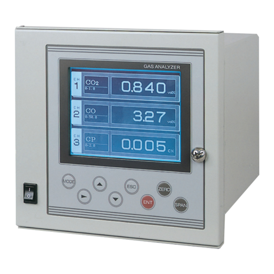
1.4 Operation panel and display operation. 1.4.1 Names of parts on the operation panel and descriptions Fig. 1-2 Operation panel Description INZ-TN3ZFG-E - 5 -... -
Page 17: Outline Of Display Screen
1.4.2 Outline of display screen (1) Measurement mode screen <Measurement screen> Function Displays concentration value. MODE Menu contents erroneous input prevention. Fig. 1-3 Display screen calculation. - 6 - INZ-TN3ZFG-E... - Page 18 CP calculation value: × × t < t < t < × INZ-TN3ZFG-E - 7 -...
-
Page 19: Before Use
2. BEFORE USE DANGER CAUTION injury, etc. injury. 2.1 Installation CAUTION - 8 - INZ-TN3ZFG-E... -
Page 20: Standard Panel Mounting
2.2 Mounting method Fig. 2-1 Panel cut dimensions 2.2.1 Standard panel mounting Fig. 2-2 Standard panel mounting INZ-TN3ZFG-E - 9 -... - Page 21 Fig. 2-3 Panel auxiliary plate mounting - 10 - INZ-TN3ZFG-E...
- Page 22 2.2.3 Panel auxiliary plate (Simple type) option Fig. 2-4 Panel auxiliary plate mounting INZ-TN3ZFG-E - 11 -...
-
Page 23: Piping Method
2.3 Piping method 2.3.1 Caution on piping DANGER For piping, be sure to observe the following cautions. Wrong piping may cause gas leakage. If the leaking gas contains a toxic component, there is a risk of serious accident being induced. 2.3.2 Piping Fig. - Page 24 2.3.3 Sampling (1) Sample gas condition (3) Preparation for standard gas Zero gas (4) Analyzer interior purging ospheric air at the installation. or the air for instrumentation. (5) Pressure at sample gas outlet Arrange so that sample gas outlet is at atmospheric pressure. (6) Example of piping connection INZ-TN3ZFG-E - 13 -...
-
Page 25: Power Supply
2.4 Wiring CAUTION may result. Fig. 2-7 The rear panel of main unit 2.4.1 Power supply Fig. 2-8 Power supply terminal - 14 - INZ-TN3ZFG-E... - Page 26 When noise emission source is near the analyzer 2.4.2 External input/output signal connection + − + − + − + − + + − − Fig. 2-9 External input/output signal terminal (1) Analog output signal : Terminal block Caution INZ-TN3ZFG-E - 15 -...
- Page 27 (2) Remote range selection input signal : Terminal block (option) It is for a contact input at no voltage. Do not apply voltage to terminals. : Terminal block (option) (4) Error contact output signal : Terminal block (5) Remote hold input signal: Terminal block It is for a contact input at no voltage.
-
Page 28: Warm-Up Operation
3. OPERATION 3.1 Warm-up operation Caution on operation may result. Caution on warm-up INZ-TN3ZFG-E - 17 -... -
Page 29: Preparation For Measurement
3.2 Preparation for measurement 3.2.1 Span concentration value setting (See “4.2.2” for setting method.) value for each component range. 3.2.3 Zero/span calibration (See “4.1” for the setting method.) 3.3 Starting and exiting measurement 3.3.1 Starting measurement 3.3.2 Exiting measurement 3.3.3 Stopping operation - 18 - INZ-TN3ZFG-E... -
Page 30: Zero/Span Calibration
4. CALIBRATION AND MODE SELECTION 4.1 Zero/span calibration 4.1.1 Zero/span calibration Caution on calibration ZERO Pressing the ZERO Setting contents Press the key on the measurement screen. ZERO key. key to move the cursor to the air for zero gas. Caution on calibration key. -
Page 31: Span Calibration
4.1.2 Span calibration Caution on calibration SPAN Pressing the SPAN Setting contents Operation in the case where “both” is selected. key on the measurement screen. SPAN key. key. keys. key. Caution on calibration tion, press the key. key. MODE - 20 - INZ-TN3ZFG-E... - Page 32 Operation in the case where “each” is selected. key on the measurement screen. SPAN key. key. keys. min. key. Caution on calibration tion, press the key. key. MODE INZ-TN3ZFG-E - 21 -...
-
Page 33: Switching Ranges
4.2 Menu mode 4.2.1 Switching ranges Initial value using the key. Caution on setting “Remote range is ON” “Output option is provided” keys. * “ON/OFF” can be selected only key. when the output option is provided. signal. input. “OFF” key. “No output option”... -
Page 34: Setting Range
4.2.2 Setting span concentration value range. Setting range each range. Initial value or full scale value key. keys, key. key. Press the , the , or the key. components in the same manner. Caution on setting setting, press the key. INZ-TN3ZFG-E - 23 -... -
Page 35: Keypad Lock
4.2.3 Keypad lock Setting contents Initial value Caution on setting key. MODE using keys, key. keys. key to register the setting value. appears again. Caution on setting To cancel the setting, press the key. - 24 - INZ-TN3ZFG-E... -
Page 36: Output Hold
4.2.4 Output hold Setting contents Initial value (1) Setting method using the key. keys. key returns to the time. , the , or the key. Press the key to register the setting value, “ON” setting again. “OFF” setting Caution on setting To cancel the setting, press the key. - Page 37 (2) Operation Caution on operation ZERO SPAN - 26 - INZ-TN3ZFG-E...
-
Page 38: Display Setting
4.2.5 Display setting Setting contents Initial value set time elapses. The setting time range is OFF condition light automatically goes off. ON condition stays off, it automatically comes on. (1) Turning off the backlight key. keys. setting value. keys. “ON” setting “OFF”... -
Page 39: Brightness Adjustment
(2) Brightness adjustment or the keys, key. keys. key to register the setting value. Caution on setting To cancel the setting, press the key. - 28 - INZ-TN3ZFG-E... - Page 40 4.2.6 Setting CP calculation value conditions Caution on handling Setting range Initial value using the key. (1) CO concentration setting using the Setting complete key. key. (Measured key to return to the previous screen. value) (Regular value) value using the keys.
- Page 41 (2) Furnace temperature setting Enter temporary furnace temperature value. key. the value using the keys. Press the key to return to the previous screen. Setting complete - 30 - INZ-TN3ZFG-E...
-
Page 42: Maintenance Mode
4.2.7 Maintenance mode Initial password key. , the , or the key. appears. “NG” “OK” Caution on setting To cancel the setting, press the key. INZ-TN3ZFG-E - 31 -... -
Page 43: Selecting Output
4.3 Maintenance mode Caution on operation 4.3.1 Selecting output Caution on setting Initial value Setting contents Jumper switching service engineer. - 32 - INZ-TN3ZFG-E... - Page 44 Layout drawing of jumper INZ-TN3ZFG-E - 33 -...
- Page 45 key. key. The cursor moves. keys. Press the key to return to the previous screen. same manner. - 34 - INZ-TN3ZFG-E...
- Page 46 4.3.2 Adjusting output Tolerance of output value Preparation for the setting analog output connector. Caution on setting eration. meter or a voltmeter. key. using the , the , or the key. Press the value using the keys. At this time, make the setting so that the ammeter output signal Press the The output signal selection screen appears again.
-
Page 47: Response Time
4.3.3 Response time Caution on use Setting range Initial value key. keys. Press the value using the keys. Press the The previous screen appears again. Setting complete - 36 - INZ-TN3ZFG-E... - Page 48 4.3.4 Minus display Setting contents Initial value key. key again, the cursor moves to the screen appears again. Setting complete INZ-TN3ZFG-E - 37 -...
-
Page 49: Password Setting
4.3.5 Password setting Caution on setting Setting range Initial value Common password key. key again, the cursor moves to value using the keys. Press the Setting complete - 38 - INZ-TN3ZFG-E... -
Page 50: Sensor Input
4.3.6 Sensor input Description of the screen Displays sensor components. : Displays the values imme- in count values. Input value Sensor Caution on operation key. key to return to the previous screen. INZ-TN3ZFG-E - 39 -... - Page 51 Caution on operation using the keys. right. key to enter <Offset screen> <Calibration screen> to return to the previous screen. - 40 - INZ-TN3ZFG-E...
-
Page 52: Factory Mode
4.3.8 Factory mode Description of the screen INZ-TN3ZFG-E - 41 -... -
Page 53: Inspection And Maintenance
5. INSPECTION AND MAINTENANCE 5.1 Daily inspection (1) Zero/span calibration 5.2 Periodic inspection maintenance Table 5-1 Maintenance and checking table Phenomena sample cell. Portions to Zero point of gas analyzer Portions to analyzer point phenomena that paper Gas analyzer phenomena that Gas analyzer output After overhaul Instrument error test... -
Page 54: Long Term Maintenance
5.3 Long term maintenance Gas analyzer annual inspection plan installation Installation Infrared gas analyzer annual inspection plan sheet Recommended Year Component name Q’ty replacement Delivered 10th period (year) year year year year year year year year year year year Galvanic fuel cell O analyzer Infrared light source unit O-ring for sampling cell... - Page 55 5.4 Details of maintenance procedures 5.4.1 Internal composition 5.4.2 Replacing power fuse Caution on replacement the rear face. Fig. 5-1 Rear face - 44 - INZ-TN3ZFG-E...
-
Page 56: Cleaning Measurement Cell
5.4.3 Cleaning measurement cell Caution on cleaning Cleaning the block cell (See Fig. 5-2) cloth. Caution Caution INZ-TN3ZFG-E - 45 -... - Page 57 Filter Detector Fig. 5-2 Composition of measurement unit (block cell) - 46 - INZ-TN3ZFG-E...
- Page 58 5.5 Airtight test 5.5.1 Airtight test inlet. regulator. regulator. Fig. 5-3 Airtight test pressure regulator. Caution on performing the test INZ-TN3ZFG-E - 47 -...
-
Page 59: Adjustment In Heat Treatment Furnace
5.6 Adjustment in heat treatment furnace What is the adjustment in heat treatment furnaces? or Air in any case so that zero point plant gases. (1) Method for span calibration by standard gas with the same composition as plant gas - 48 - INZ-TN3ZFG-E... - Page 60 (2) Method for span calibration by check gas value. INZ-TN3ZFG-E - 49 -...
-
Page 61: Troubleshooting
6. TROUBLESHOOTING CAUTION electrical shock or personal injury. 6.1 Problem conditions and corrective action Phenomena Items Press the key. Display connector faulty Fuse faulty Improper sealing Gas leak - 50 - INZ-TN3ZFG-E... -
Page 62: Error Message
6.2 Error message Error contents <Screen display and operation at the occurrence of error> INZ-TN3ZFG-E - 51 -... - Page 63 - 52 - INZ-TN3ZFG-E...
-
Page 64: Specifications
7. SPECIFICATIONS Material of gas-contacting parts: Gas inlet/outlet; SUS304, Sample cell; SUS304/neoprene Measuring system: rubber, Infrared-ray transmitting window; C Non-dispersive infrared absorption method with single Internal tubing; Toaron light source and single beam (single beam method) Gas inlet/outlet: Measurable gas components and measuring range: Min. -
Page 65: Installation Condition
Remote output holding (optional): Output signal is held at the latest value or setting value by short-circuiting the remote output holding input terminals. Holding is maintained while the terminals are short-circuited. Indication values will not be held. Remote range changeover (optional): Range is selected by the contact input signal. - Page 66 Standard gas sampling system Principle diagram of NDIR type measurement (For CO, CO , CH INZ-TN3ZFG-E - 55 -...
-
Page 67: Code Symbols
7.2 Code symbols 4 5 6 7 9 10 11 12 13 14 15 16 Digit Specification Standard 1st component 2nd component Measurable Without components Without Without Gas inlet/outlet R c 1/4 connection NPT1/4 4 to 20mA DC Output signal 0 to 1V DC 0 to 100mV DC 0 to 10mV DC... - Page 68 Correspondence table of the possible measuring ranges Table 1: Single-component analyzer <CO > 2nd range 0 to 1% 0 to 2% 0 to 3% 0 to 5% 0 to 10% 0 to 20% 0 to 25% 0 to 40% 0 to 50% 0 to 70% 0 to 100% 1st range Without H 0 to 0.5%...
- Page 69 Correspondence table of the possible measuring ranges Table 4: Two-component analyzer <CO /CO> 1st component <CO > 2nd component <CO> 1st range/2nd range 1st range/ 0 to 0.5 0 to 1 0 to 1 0 to 2 0 to 2 0 to 3 0 to 5 0 to 10...
- Page 70 Instrumentation & Sensors Planning Dept. 1, Fuji-machi, Hino-city, Tokyo 191-8502, Japan http://www.fujielectric.com Phone: +81-42-514-8930 Fax: +81-42-583-8275 http://www.fujielectric.com/products/instruments/...
Need help?
Do you have a question about the ZFG and is the answer not in the manual?
Questions and answers