Advertisement
Quick Links
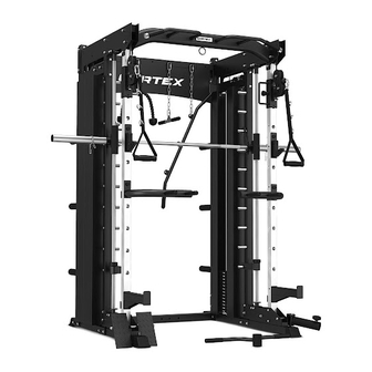
SM26 Multi Gym
(Dual Stack Functional Trainer,
Smith Machine, Half Rack)
USER MANUAL
Product may vary slightly from the item pictured due to model upgrades.
Read all instructions carefully before using this product.
Retain this owner's manual for future reference.
NOTE:
This manual may be subject to updates or changes. Up to date manuals are available through our
website at www.lifespanfitness.com.au
Advertisement

Related Manuals for Cortex SM26 Multi Gym


Summary of Contents for Cortex SM26 Multi Gym
- Page 1 SM26 Multi Gym (Dual Stack Functional Trainer, Smith Machine, Half Rack) USER MANUAL Product may vary slightly from the item pictured due to model upgrades. Read all instructions carefully before using this product. Retain this owner’s manual for future reference.
-
Page 2: Table Of Contents
TABLE OF CONTENTS Important Safety Instructions ....... 03 II. Care Instructions ..........04 III. -
Page 3: Important Safety Instructions
I. IMPORTANT SAFETY INSTRUCTIONS WARNING: Read all instructions before using this machine. To ensure your safety, read the following precautions before using this product 1. Please read, study and understand the instructions and all warning labels before use. (It is recommended to be familiar with the normal operation and use methods of the device before using this product. -
Page 4: Care Instructions
II. CARE INSTRUCTIONS • Lubricate moving joints with silicon spray after periods of usage. • Be careful not to damage plastic or metal parts of the machine with heavy or sharp objects. • The machine can be kept clean by wiping it down using dry cloth. •... -
Page 5: Parts List
III. PARTS LIST Name Qty. Name Qty. Back Column Bottom Side Covers Central Pillar The Sleeve Hanging Rod Front Vertical Tube Counterweight Plate Bottom Side Beams Weight Rear Bottom Beam Full Net Cover Left Smith Guide Rod Full Net Cover Right Stainless Steel Guide Rod Pattern Plate Shaft Top Rear Beam... - Page 6 Name Qty. Name Qty. External Hexagon Bolt M10x95 Nut M8 External Hexagon Bolt M10x90 National Standard Nut M6 Φ10 Washer External Hexagon Bolt M10x75 Φ8 Washer External Hexagon Bolt M10x70 External Hexagon Bolt M10x45 Lock Pin External Hexagon Bolt M10x20 Rear Decorative Board External Hexagon Bolt M10x90 Tricep Rope...
- Page 7 PARTS LIST |...
- Page 8 | PARTS LIST...
-
Page 9: Assembly Instructions
IV. ASSEMBLY INSTRUCTIONS NOTE: 1. The gasket shall be placed at both ends of the bolts (against the bolt head and nuts), unless otherwise stated. 2. Preliminary assembly is hand tightening of all bolts and nuts and hand tightening with the wrench for complete assembly. 3. - Page 10 STEP 2 1. Place counter-pad (52 #) hole on (4#) as shown and insert (7#). 2. Repeat for the other side. STEP 3 1. Place the (2#) column on (4#) as shown and secure with bolts (64#), gaskets (74#) and nuts (71#). 2.
- Page 11 STEP 4 1. Place the counterweight block (35#) into (7#) according to the drawing, then insert the (34#) counterweight head and (15#) counterweight bar. Fix with L-shaped counterweight pin (55#). 2. Insert (79#), (80#) according to the figure. 3. Repeat for the other side. ASSEMBLY INSTRUCTIONS |...
- Page 12 STEP 5 1. Place the rear upper beam (8#) and flat connection plate (50#) on both sides of (1#) as shown. Fix with bolt (66#) pads, plate (74#) and nut (71#). 2. Insert sleeve (33#) into (1#) and secure with bolt (68#) spacer (74#). Insert sleeve (44#) into (33#) and card (53#) into (44#).
- Page 13 STEP 6 1. Place counterweight loading (10#), flat connection plate (49#) on both sides of (1 #) and (2#) as shown. Fix with bolt (66#), gasket (74#), and nut (71#). 2. Repeat on the other side. NOTE: Align (7 #) to hole (10 #) and tighten the (10 #) pre-loaded nut. 71 9 STEP 7 1.
- Page 14 STEP 8 1. Place the rear trim plate (77#) on the side of (1#) and (8#) and secure with the bolt (66#), gasket (74#), and nut (71#). 2. Place the upper trim plate (31#) and the lower holes on (9#) and (2#). Secure the bolt (65#), gasket (74#) and nut (71#).
- Page 15 STEP 9 1. Set the cable adjuster sleeve (19#) with lock pin (76#). 2. Align the holes on (3#) to the parts (31#) and (32#) and secure with bolts (65#), gasket (74#) and nut (71#). 3. Repeat for the other side. ASSEMBLY INSTRUCTIONS |...
- Page 16 STEP 10 1. According for the figure, install the lead handles (16#) and (17#) on the front upper beam (11#) and secure with bolts (68#) and spacer (74#). 2. Place the installed (11#) holes on both sides of (31#) and secure with bolt (65#), gasket (74#), and nuts (71#).
- Page 17 STEP 11 1. Twist the small pulley frame (39#) into (15#) as shown, then place the short optical shaft (44#) into (2#) with pre-installed bolts. 2. Place the pulley bracket (26#) into the hole of (19#) and secure with bolt (62#), gasket (74#), and nut (71#).
- Page 18 Direction of wire diagram. | ASSEMBLY INSTRUCTIONS...
- Page 19 STEP 12 First run the cable rope through the pulleys, then install the pulley and pulley separator (56# & 57#) and fix using bolts (65#), (66#), gaskets (74#) and nuts (71#) as shown in diagram. Repeat for the other side. ASSEMBLY INSTRUCTIONS |...
- Page 20 STEP 13 1. Place the Foot plate (18#) on both sides of (32#) according to the picture. Fit the (38#) into the foot plate shaft and secure with (68#) spacer and (68#). 2. First place the M10 knob (54#) on the landmine post (27#). Install (27#) on the barrel shaft (45#) and then place (45#) hole into (32#) with bolt using nut (71#), bolt (64#) and washer (74#).
- Page 21 STEP 14 1. First install (36#) and (37#) onto the holes on (4#) and (10#) using bolts (68#), insert (74#) and then fix the 2 plates with bolts (70#) and nut (73#). 2. Attach the handle (51#) on C type buckle (59#) and then attach (59#) to the pulley rope. 3.
- Page 22 STEP 15 1. According to the diagram, set up the light shaft bottom set (46#), safety hook (24#), damping pad (52#), bearing sleeve (25#) with bolt (68#) and gasket (74#), then set the light shaft upper set (47#). 2. Pass the rod (12#) into (25#) and buckle the hook (41#), (42#) to (12#). | ASSEMBLY INSTRUCTIONS...
- Page 23 STEP 16 1. Secure the installed Olympic rod onto the side covers (31#) and (32#) as shown, using bolt (69#), gasket (75#), and nut (72#). Please ensure to tighten all bolt and nuts with a wrench. Check that all pulleys and wire ropes are secured properly. If cables are not sliding smoothly then the bolts on the pulley may be over tighten, loosen it slightly.
-
Page 24: Exercise Guide
V. EXERCISE GUIDE PLEASE NOTE: Before beginning any exercise program, consult your physician. This is important especially if you are over the age of 45 or individuals with pre-existing health problems. The pulse sensors are not medical devices. Various factors, including the user’s movement, may affect the accuracy of heart rate readings. -
Page 25: Maintenance
VI. MAINTENANCE MAINTENANCE METHOD: To extend the service life of the device, the parts must be lubricated on time. The product has been initially lubricated before leaving the factory, but lubrication is required between the guide rod and the weight plate over time. NOTE: Silicon oil/spray is recommended for lubrication. -
Page 26: Warranty
VII. WARRANTY AUSTRALIAN CONSUMER LAW Many of our products come with a guarantee or warranty from the manufacturer. In addition, they come with guarantees that cannot be excluded under the Australian Consumer Law. You are entitled to a replacement or refund for a major failure and compensation for any other reasonably foreseeable loss or damage. - Page 28 WWW.LIFESPA NF ITN ES S.COM.AU...
Need help?
Do you have a question about the SM26 Multi Gym and is the answer not in the manual?
Questions and answers