Advertisement
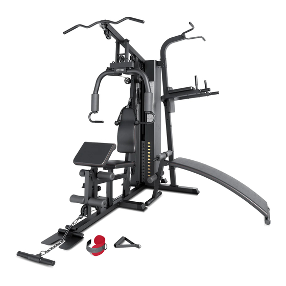
GS-6 MULTISTATION
USER MANUAL
Product may vary slightly from the item pictured due to model upgrades.
Read all instructions carefully before using this product.
Retain this owner's manual for future reference.
NOTE:
This manual may be subject to updates or changes. Up to date manuals are available through our
website at www.lifespanfitness.com.au
Advertisement

Related Manuals for Cortex GS-6


Summary of Contents for Cortex GS-6
- Page 1 GS-6 MULTISTATION USER MANUAL Product may vary slightly from the item pictured due to model upgrades. Read all instructions carefully before using this product. Retain this owner’s manual for future reference. NOTE: This manual may be subject to updates or changes. Up to date manuals are available through our...
-
Page 2: Table Of Contents
TABLE OF CONTENTS Important Safety Instructions ....... . 03 II. Care Instructions ..........04 II. -
Page 3: Important Safety Instructions
I. IMPORTANT SAFETY INSTRUCTIONS WARNING: Read all instructions before using this machine. • Install the product on a flat level surface. • Place your unit on a solid, level surface when in use. • Never allow children on or near the machine. •... -
Page 4: Care Instructions
II. CARE INSTRUCTIONS • Lubricate moving joints with silicon spray after periods of usage. • Be careful not to damage plastic or metal parts of the machine with heavy or sharp objects. • The machine can be kept clean by wiping it down using dry cloth. •... -
Page 5: Parts List
II. PARTS LIST Some items on this list may come pre-installed on your equipment. If you feel like you’re missing anything, please double check your equipment. PARTS LIST |... - Page 6 | PARTS LIST...
- Page 7 370mm 230mm PARTS LIST |...
- Page 8 Key No. Description Qty. Key No. Description Qty. Guide Rods Press Foam Front Vertical Frame Seat Frame Main Seat Support Lampstand Washers Φ8 Support Tube Rubber Bumper Hex Bolt M8x40 Bolt M6x16 Arm Frame PlugΦ25x3xΦ22x7 Arm Pad Plug 50x70 Hex Bolt M8x16 Front Press Base Tube Cover Plug 50x25...
- Page 9 Key No. Description Qty. Key No. Description Qty. Board Plate (4 holes) Foot Plate Hex Bolt M8x10 Triceps Cable (4215mm) Foot Plate Tube 270mm Lat Cable (3380mm) Pipe Bushing Butterfly Cable (3115mm) Support Tube C-clip Foot Tube Triceps Rope Tube Plug 60x30 6 Chain Parallel Support Lat Bar...
-
Page 10: Assembly Instructions
III. ASSEMBLY INSTRUCTIONS NOTE! 1. Washers are pushed at two ends of bolts. 2. Some parts has been assembled at the factory. 3. It is strongly recommended this machine to be assembled by two or more people to avoid possible #14 Φ10 10pcs #20 M10 8pcs #49 M10X20 - 2pcs... - Page 11 #17 Φ10 - 4pcs #23 M10 - 2pcs #49 M10X20 - 2pcs #34 M10x90 - 2pcs STEP 2 1. Slide the 12 Weight Plates (#56) onto the Guide Rods (#1). (Note: The groove side faces down). Insert the Selector Rod (#57) through the centre hole. 2..Slide the Selector Stem (#58) onto the Guide Rod (#1).
- Page 12 #14 Φ10 - 8pcs #20 M10 - 5pcs #19 M6X35 - 2pcs #28 M10x90 - 2pcs #18 M6 - 2pcs #39 Φ8 - 2pcs #67 M10x65 - 2pcs #69 M10x110 - 1pc #54 M8x85 - 2pcs STEP 3 1. Attach the Front Press Base (#9) to the Upper Frame (#90). Secure it with 1x Long Axle (#11), Enlarged Washers(#27) and Aircraft Nut M10mm (#20).
- Page 13 #14 Φ10 - 6pcs #20 M10 - 3pcs #49 M10X20 - 2pc #31 M10x90 - 2pcs #33 M10x70 - 1pcs STEP 4 1. Attach the Main Seat Support (#4) to the Front Vertical Frame (#2). Secure it with Washer Φ10 (#14) and Aircraft Nut M10mm (#20), Carriage Bolt M10*90mm (#31), and Plate (#22).
- Page 14 41 39 37 #39 Φ8 - 4pcs #40 M8x40 - 2pcs #43 M8X16 - 2pcs STEP 5 1. Place the Seat (#38) onto the Seat Stand (#37). Secure it with Allen Bolt M8*40 (#40) and WasherΦ8 (#39). Insert the Seat Stand (#37) into the Main Seat Support (#4). Secure it with Lock Knob (#34). 2.
- Page 15 3380mm #14 Φ10 - 12pcs #20 M10 - 7pcs #21 M10X175 - 1pc #59 M10x45 - 6pcs STEP 6 1. Feed the Lat Cable (3380mm)(#75) through 7x Pulley (#63) as shown in image following, secure with 12 Washers Φ10 (#14), 6 Hex BoltsM10×45 (#59), 1 Hex Bolt M10x175(#21), 7 Nut M10 (#20), 2 Pulley plate (#65).
- Page 16 3115mm #14 Φ10 - 6pcs #20 M10 - 3pcs #59 M10x45 - 3pcs STEP 7 1. Connect the Butterfly Cable (3115mm) (#76) to Right Butterfly (#16) and Left Butterfly (#15) as shown in image, secure with 1 Pulley Set(#64), 3 Pulley (#63), 3 Hex Bolts M10x45 (#59), 6 Φ10 washers (#14), 3 Nuts(#20).
- Page 17 4215mm 14 20 64 14 #14 Φ10 - 6pcs #20 M10 - 8pcs #59 M10x45 - 7pcs STEP 8 #67 M10x65 - 1pc 1. Fix the Triceps Cable (4215mm) (#74) as shown in image, secure with 2 Pulley Set(#66), 8 Pulley (#63), 7 Hex Bolts M10x45 (#59), 1 Hex Bolt M10x65 (#67), 16 Φ10 washers (#14), 8 Nuts(#20).
- Page 18 77 82 #49 M10X20 - 1pc #14 Φ10 - 4pcs STEP 9 1. Attach Right Weight Plate Cover (#60) and (#61) to frame (#88) and (#90), secure with 2 M10x20 (#49), 2 Washers 10 (#14) . 2. Attach Lat Bar (#80) to the Lat Cable (3380mm) (#75) though 6 Chains (#79) with 2 C-clip (#77). 3.
- Page 19 14 20 67 49 20 14 14 20 #14 Φ10 - 8pcs 20 14 #20 M10 - 5pcs #49 M10X20 - 2pcs #31 M10x90 - 2pcs #67 M10x65 - 1pc STEP 10 1. Connect the parallel bar diagonal support pipe (91 #) with 2 flat gaskets 10(14 #) and 2 locknut M10(20 #) to the pre-installed carriage bolt M10x70(32 #) on the rear floor frame (extension)(88 #).
- Page 20 #14 Φ10 - 6pcs #72 M8x10 - 4pcs #20 M10 - 3pcs #54 M8x85 - 2pcs #49 M10X20 - 2pcs #110 M8x65 - 4pcs #31 M10x90 - 2pcs #39 Φ8 - 8pcs STEP 11 #33 M10x70 - 1pc 1. Attach the Left Dip Arm (#101) and the Right Dip Arm (#102) to the Vertical Frame (#91). Secure it with 1x Carriage Bolt M10*70mm (#33), 2x Washer Φ10 (#14), 1x Aircraft Nuts M10mm (#20).
- Page 21 STEP 12 1. Attach 1x Arch Frame (#3) to the Front Vertical Stand (#2). Secure it with 1x Carriage Bolt M10 x 70mm (#14), 2x Washerφ10 (#12) and 1x Allen Bolt M10mm (#13). 2. Attach the 1x Base Frame (#1) to the Front Vertical Stand (#2). Adjust the height and secure it with 1x Adjustable Position Foam Tube (#10) and 1x Lock Knob (#11).
-
Page 22: Exercise Guide
VII. EXERCISE GUIDE PLEASE NOTE: Before beginning any exercise program, consult your physician. This is important especially if you are over the age of 45 or individuals with pre-existing health problems. The pulse sensors are not medical devices. Various factors, including the user’s movement, may affect the accuracy of heart rate readings. -
Page 23: Warranty
WORKOUT GUIDELINES HEART RATE MAXIMUM TARGET ZONE COOL DOWN 20 25 30 35 40 45 50 55 60 65 70 This is how your pulse should behave during general fitness exercise. Remember to warm up and cool down for a few minutes. IV. - Page 24 WWW.L IF ESPAN F ITNE S S . COM . A U...
Need help?
Do you have a question about the GS-6 and is the answer not in the manual?
Questions and answers