Advertisement
Quick Links
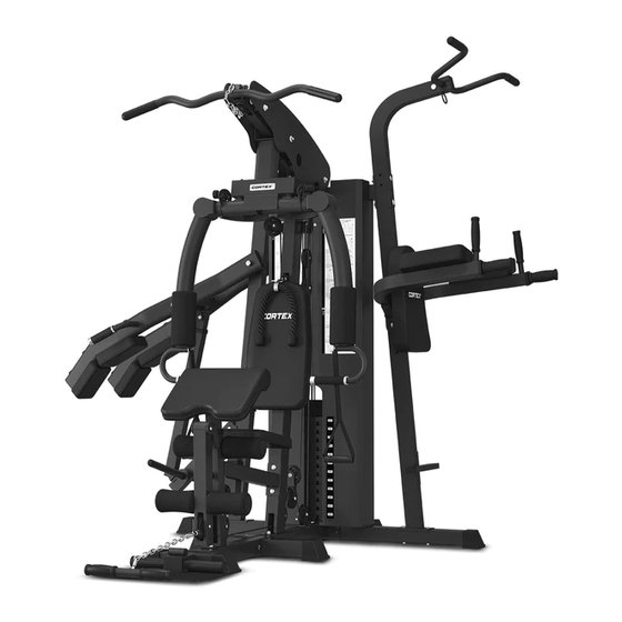
GS7 Multi Station Home Gym
USER MANUAL
Product may vary slightly from the item pictured due to model upgrades.
Read all instructions carefully before using this product.
Retain this owner's manual for future reference.
NOTE:
This manual may be subject to updates or changes. Up to date manuals are available through our
website at www.lifespanfitness.com.au
Advertisement

Subscribe to Our Youtube Channel
Related Manuals for Cortex GS7


Summary of Contents for Cortex GS7
- Page 1 GS7 Multi Station Home Gym USER MANUAL Product may vary slightly from the item pictured due to model upgrades. Read all instructions carefully before using this product. Retain this owner’s manual for future reference. NOTE: This manual may be subject to updates or changes. Up to date manuals are available through our...
-
Page 2: Table Of Contents
TABLE OF CONTENTS Important Safety Instructions ....... 03 II. Care Instructions ..........04 III. -
Page 3: Important Safety Instructions
I. IMPORTANT SAFETY INSTRUCTIONS WARNING: Read all instructions before using this machine. • Install the product on a flat level surface. • Place your unit on a solid, level surface when in use. • Never allow children on or near the machine. •... -
Page 4: Care Instructions
II. CARE INSTRUCTIONS • Lubricate moving joints with silicone spray after periods of usage. • Be careful not to damage plastic or metal parts of the machine with heavy or sharp objects. • The machine can be kept clean by wiping it down using a dry cloth. •... -
Page 5: Parts List
III. PARTS LIST Key No. Description Qty. Key No. Description Qty. Post to the ground Foam (Φ100x175) Before the ground Left Plate Cover Boat Patch Ground Welding Right Plate Cover T Post Ground Upper Beam Welded Checkered Plate Bumper Column Small Paste Ground Curved Tube Guide Rod... - Page 6 Key No. Description Qty. Key No. Description Qty. 53-6 4 Holes Plate 56-2 Bolt M10*70 53-7 56-3 25 Butterfly Card Bolt M10*20 56-4 Bolt M10*45 53-8 Spin Axis (57mm) 56-5 Bolt M10*60 53-9 Spin Axis (100mm) 56-6 Bolt M8*10 53-10 Spin Axis (208mm) 56-7 Bolt M8*16...
- Page 7 PARTS LIST |...
- Page 8 53-1 53-2 53-3 53-4 53-5 53-6 53-7 53-8 53-9 53-10 54-1 54-2 54-3 54-4 54-5 54-6 54-9 54-10 54-11 54-12 56-1 56-2 56-3 56-4 56-5 56-6 56-7 56-8 56-9 56-10 56-11 56-12 56-13 56-14 56-15 56-16 56-17 | PARTS LIST...
-
Page 9: Assembly Instructions
IV. ASSEMBLY INSTRUCTIONS ATTENTION: 1. The gasket shall be placed at both ends of the bolts (against the bolt head and nut), if indicated otherwise. 2. Preliminary assembly is hand tightening all bolts and nuts and tightening with wrench for complete assembly. - Page 10 56-4 54-6 56-14 54-1 56-3 STEP 2 1. With three holes facing up, insert (#7) into the (#1) and secure with mounting hole with: - 2 Bolts (#56-3) - 2 spacers (#56-12) Then insert (#54-1) into (#7). 2. Place the counterweight block (#57) into (#7) one by one (Note that the counterweight block groove joint is uniformly facing down).
- Page 11 56-2 56-12 53-1 56-14 56-14 56-1 56-12 56-3 53-3 53-8 56-14 STEP 3 1. Lock the lower end of (#10) and (#2) with: - 2 Pads (#56-12) - 2 Nuts (#56-14) 2. Set (#11) into the (#2) pre-installed bolt first, and lock it with: - 2 Spacers (#56-12) - 2 Nuts (#56-14) 3.
- Page 12 56-1 56-3 53-3 53-9 56-3 56-14 56-14 56-13 56-12 STEP 4 1. Cover (#7) into the (#13) rear square tube mounting hole as shown, secure with: - Bolts (#56-3) - Gasket (#56-12) 2. Connect (#53-3) to (#13) and (#13) to (#10) with: - Bolts (#56-1) - Gaskets (#56-12) - Nuts (#56-14)
- Page 13 22-1 53-2 22-3 22-2 53-4 STEP 5 After the whole instrument is assembled, check if the wire rope is tightened. If the wire rope is slightly loose, adjust by tightening the lower bolts of the tensile wire rope (#22-1). If the wire rope is loose, adjust the pulley mounting hole position adjustment through the pulley adjustment sheet (#53-2).
- Page 14 54-5 56-2 56-14 56-2 56-4 54-5 STEP 6 NOTE: Wire rope must be fed into the pulley before securing the pulley. | ASSEMBLY INSTRUCTIONS...
- Page 15 56-9 56-12 56-7 56-8 54-4 54-4 STEP 7 1. Install (#19) to (#10) with: - 2x Bolts (#56-9) - 2x Gaskets (#56-12) 2. Install (#20) to (#17) with: - 2x Bolts (#56-8) - 2x Spacers (#56-12) 3. Install (#21) to (#18) with: - 2x Bolts (#56-7) - 2x Spacers (#56-12) 4.
- Page 16 56-12 56-7 56-7 STEP 8 1. Place (#48) on (#13) side and secure with (#56-7) bolts and (#56-12) gaskets. 54-3 STEP 9 1. Insert (#28) foam pipe into (#12), then insert from pipe head to (#29) and (#54-3) onto (#28). | ASSEMBLY INSTRUCTIONS...
- Page 17 56-16 56-17 54-11 56-7 56-15 54-9 56-12 54-12 56-7 56-7 53-5 54-10 54-11 54-11 STEP 10 1. Install parts (#30) and (#31) with (#56-7) nuts, (#56-12) gaskets and (#56-15) bolts onto parts (#13), (#1) and (#2). Attach the accessories and weight pin: 1.
- Page 18 56-2 56-3 56-12 56-1 56-12 56-14 56-3 53-3 53-3 56-12 56-1 56-14 56-12 56-14 56-12 53-3 56-1 56-14 56-12 STEP 11 1. Install (#35) on (#34) and secure it with: 4. Install the installed (#33) on (#1) and tighten - Bolts (#56-2) it with: - Bolts (#56-3) - Flat pads (#56-12)
- Page 19 56-10 56-12 53-6 56-2 56-6 56-12 56-12 56-3 56-12 56-9 56-14 STEP 12 1. Install (#36) and (#37) to (#33) and secure with: 3. Install (#50) to (#36) and (#37) - Bolts (#56-2) respectively with: - Flat spacers (#56-12) - Bolts (#56-9) - Nuts (#56-14) - Flat spacers (#56-12) - Plate (#53-6)
- Page 20 56-1 56-12 53-3 53-3 56-1 56-12 56-14 56-14 56-2 56-3 53-8 56-14 STEP 13 1. Install (#32) on (#13) as shown, and secure 3. Installation diagram attaches two (#41) to it with: (#40) and fixed with: - Plate (#53-3) - Bolts (#56-2) - Bolts (#56-1) - Flat spacers (#56-12) - Flat spacers (#56-12)
- Page 21 56-12 56-3 53-10 56-5 56-11 56-11 56-3 53-8 56-3 54-2 53-8 56-3 STEP 14 1. Install (#46) and (#47) to both sides of (#45), and secure them with: - Bolts (#56-5) - Flat pads (#56-12) - Nuts (#56-14) 2. Place them onto (#40) and feed part (#53-10) though them then secure with: - Bolts (#56-3) - Flat pads (#56-12) 3.
- Page 22 4. Install (#53-8) to (#44), and then install (#44) to (#45) with: - Bolts (#56-3) - Flat spacers (#56-12). 5. Similarly, install (#53-8) to (#43), and then install (#43) to (#42) with: - Bolts (#56-3) - Flat spacers (#56-12) 6. Install (#51) and (#52) on (#46) and (#47) and be tightened with: - Bolts (#56-11) - Flat spacers (#56-12) Ensure to tighten all Nuts and Bolts with a wrench.
-
Page 23: Maintenance Instructions
V. MAINTENANCE INSTRUCTIONS MAINTENANCE METHOD: To extend the service life of the device, the parts must be lubricated on time. The product has been initially lubricated before leaving the factory, but lubrication is required between the guide rod and the weight plate over time. NOTE: Silicon oil/spray is recommended for lubrication. -
Page 24: Exercise Guide
VI. EXERCISE GUIDE PLEASE NOTE: Before beginning any exercise program, consult your physician. This is important for individuals over the age of 45 or with pre-existing health problems. The pulse sensors are not medical devices. Various factors, including the user’s movement, may affect the accuracy of heart rate readings. - Page 25 COOL DOWN Finish each workout with a light jog or walk for at least 1 minute. Then complete 5 to 10 minutes of stretching to cool down. This will increase the flexibility of your muscles and will help prevent post- exercise problems.
-
Page 26: Warranty
VII. WARRANTY AUSTRALIAN CONSUMER LAW Many of our products come with a guarantee or warranty from the manufacturer. In addition, they come with guarantees that cannot be excluded under the Australian Consumer Law. You are entitled to a replacement or refund for a major failure and compensation for any other reasonably foreseeable loss or damage. - Page 28 WWW.LIFESPA NF ITN ES S.COM.AU...
Need help?
Do you have a question about the GS7 and is the answer not in the manual?
Questions and answers