
Related Manuals for Henny Penny FlexFusion FM08-454-G


Summary of Contents for Henny Penny FlexFusion FM08-454-G
- Page 1 Installation manual Read the operating instructions prior to commissioning FlexFusion® ELECTRIC GOLD COMBI Model FGE-615 FGE-621 FGE-115 FGE-121 FGE-215 FGE-221 FM08-454-G en-US...
- Page 2 Henny Penny Corporation P.O.Box 60 Eaton,OH 45320 Phone +1 937 456-8400 Fax +1 937 456-8402 Toll free in USA Phone +1 937 417-8417 Fax +1 937 417-8434 www.hennypenny.com Installation instructions...
-
Page 3: Table Of Contents
Directory of contents 1 Introduction ................. 5 1.1 About this manual ................ 5 1.1.1 Explanation of signs .................. 6 1.2 Personnel qualifications .............. 7 1.3 Use of the unit ................... 7 1.4 Warranty .................... 7 2 Safety instructions ............. 8 3 Description of the unit ............. 10 3.1 Overview of the unit ............... 10 3.1.1 Countertop unit ... - Page 4 Directory of contents 6.3.2 Changing the basic setting of the control .......... 41 6.4 Making the water connection ............ 42 6.4.1 Connecting the drinking water connection line ........ 43 6.4.2 Connecting softened drinking water to both connections ...... 44 6.5 Making the waste water connection .......... 45 6.5.1 Determining the type of connection to the sewer system ...
-
Page 5: 1 Introduction
Introduction 1 Introduction 1.1 About this manual The installation instructions are part of the unit and contain information on safe installation of the unit. Observe the following notes and adhere to them: • Read the installation instructions completely prior to installation. •... -
Page 6: Explanation Of Signs
Introduction 1.1.1 Explanation of signs Imminent danger DANGER Failure to comply will lead to death or very severe injuries. Potential danger WARNING Failure to comply can lead to death or very severe injuries. Dangerous situation CAUTION Failure to comply can lead do slight to moderately severe injuries. Property damage NOTICE Failure to comply can cause property damage. -
Page 7: Personnel Qualifications
Introduction 1.2 Personnel qualifications Explanation of qualification Skilled personnel • A skilled person is someone who, on the basis of their technical training, knowledge and experience as well as familiarity with the applicable standards, can assess the assigned work and recognize pos- sible dangers. -
Page 8: 2 Safety Instructions
Safety instructions 2 Safety instructions The unit complies with applicable safety standards. Residual risks associated with operation or risks resulting from incorrect operation cannot be ruled out and are mentioned specifically in the safety instructions and warnings. The installation fitter must be familiar with regional regulations and observe them. - Page 9 Safety instructions Installation Risk of property damage and personal injury from improper installation • Ensure that the installation area has adequate load-bearing capacity. • Wear safety shoes and protective gloves. Electrical connection Risk of fire from improper connection • Observe applicable regional regulations of the electric supplier. •...
-
Page 10: 3 Description Of The Unit
Description of the unit 3 Description of the unit 3.1 Overview of the unit 3.1.1 Countertop unit Image: Image: Unit with tray rack trolley a Tray rack j Hand shower b Insulating disk k Nameplate c Door handle l Base frame (optional) d Cooking chamber door m Unit foot e Tray rack trolley (optional) -
Page 11: Floor-Standing Unit
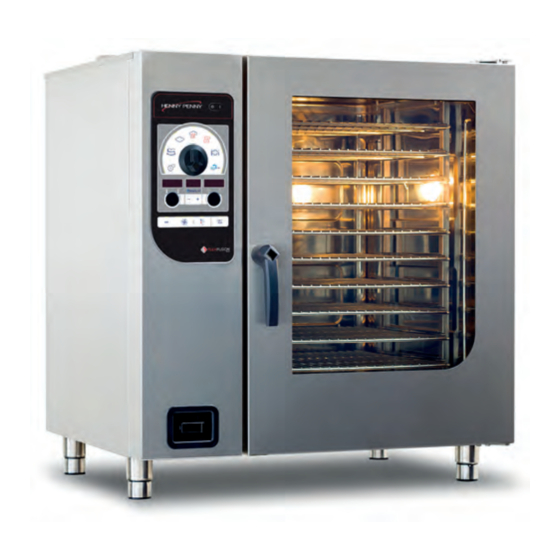
Description of the unit 3.1.2 Floor-standing unit Image: Image: Unit with tray trolley a Tray rack i USB port (covered) b Insulating disk j Hand shower c Door handle k Nameplate d Cooking chamber door l Unit leg e Guide rail (right) m Operating unit f Tray trolley n Housing... -
Page 12: Planning Drawing
Description of the unit 3.2 Planning drawing Image: Sizes 6XX and 1XX Image: Size 2XX Size 615, 621 115, 121 215, 221 50 (1,97) 50 (1,97) 50 (1,97) 997 (39,25) 997 (39,25) 1075 (42,32) 50 (1,97) 50 (1,97) 50 (1,97) 50 (1,97) 50 (1,97) 50 (1,97) -
Page 13: Unit And Connection Data
Description of the unit 3.3 Unit and connection data • All voltages listed below are technically available. INFORMATION • For some voltages, however, the implementation must be agreed with the manufacturer. • The voltage for which the device is designed is indicated on the nameplate. Size Dimensions Unit... - Page 14 Description of the unit Size Cooking chamber light Illuminant Halogen oven lamp 20 W 12 V G4 Energy efficiency class Electrical connection Protective system IPX5, IPX6 (optional) Type of connection 3PE / AC 50/60Hz, 3NPE / AC 50/60Hz Voltage (V) Connected load (kW) 10.1 16.3...
- Page 15 Description of the unit Size Softened drinking water connection Water type Softened drinking water, cold Residual hardness CaCO < 1 (100 ppm) (mmol/l (ppm)) Chloride Cl (mg/l) < 100 Iron Fe (mg/l) < 0.2 Connection pressure (kPa (psi)) 200 (29) — 600 (87) Connection (") R 3/4 Drinking water connection...
- Page 16 Description of the unit Fastening to the floor Absolutely essential for the following unit types FGE615 Only in conjunction with base cabinet and underframe FGE621 FGE115 FGE121 FGE121-621 Only in conjunction with stacking kit FGE115-621 FGE121-615 FGE115-615 Transformer voltage Type of connection 3NPE / AC 50/60 Hz, 3PE / AC 50/60 Hz Voltage range (V) 208 —...
- Page 17 Description of the unit Basic setting of the control Basic setting Parameter Standard Range of Explanation value adjustment Supply voltage 100 — 500 V Enter the local, mean voltage between the line conductors. Altitude 0 = 0 — 999 m Request the altitude above sea level from (3277 ft) the local weather station.
-
Page 18: 4 Transporting The Unit
Transporting the unit 4 Transporting the unit Risk of property damage and personnel injury from tipping unit CAUTION • Stay clear of lifted unit. • Move lifted unit carefully. Risk of property damage from improper transport NOTICE • Transport the unit upright. •... -
Page 19: Unpacking The Unit
Transporting the unit 4.2 Unpacking the unit Risk of injury from sharp edges CAUTION • Wear protective gloves. When unpacking the unit, inspect it for transport damage. INFORMATION Do not install damaged units or put into service. 1. Remove the packaging. 2. -
Page 20: 5 Installing The Unit
Installing the unit 5 Installing the unit Risk of burns from spraying hot fat WARNING • Install deep-fat fryers outside the range of the hand shower. Danger of the unit tipping over on casters WARNING If the unit is tilted on casters, it may tip over and seriously injure you. •... - Page 21 Installing the unit D ** * Depends on the kitchen ventilation system and quality of ceiling material ** For service work 500 mm (19,69 in) recommended The following clearances from walls, ceilings or other equipment must be maintained when installing the unit: •...
-
Page 22: Lifting The Unit Off The Pallet
Installing the unit 5.2 Lifting the unit off the pallet Risk of property damage and personnel injury from tipping unit CAUTION • Stay clear of lifted unit. • Move lifted unit carefully. Risk of property damage from lifting the unit incorrectly NOTICE •... -
Page 23: Setting Up The Unit On A Base Frame
Installing the unit 5.4 Setting up the unit on a base frame Image: Setting up the unit on a base frame a Lift fork d Stud bolt b Waste trap on the unit e Unit leg c Base frame f Unit Prerequisite The base frame must carry the weight of the unit Base frame levelled Base frame must be set up in accordance with the planning drawing... -
Page 24: Installing The Support Rack
Installing the unit 5.4.1 Installing the support rack Depending on the version, the base frame can be equipped with a hang-in frame. The hang-in the frame is used to hold containers, baking sheets and grates. Image: A Stop profile, B Hang-in frame a Stop profile c Outboard support rack b Bolt... - Page 25 Installing the unit Aligning tray trolley Prerequisite The floor under and in front of the unit is flat 1. Level the unit by screwing the equipment legs in or out. 2. With poor floor conditions, place spacers on the casters of the tray trolley.
-
Page 26: Fastening The Unit To The Floor
Installing the unit 7. Move tray trolley into the unit until it stops and check the alignment. The support rollers of the inserted tray trolley no longer have floor contact. 8. Remove the push handle. 9. Close the cooking zone door. 10.Fill out the start-up operation report. - Page 27 Installing the unit To prevent the unit from tilting, a special fastening kit is supplied by the manufacturer or is available as an accessory. The fastening kit contains two floor fasteners and all components required to bolt or bond to the floor. The unit or underframe is fastened by means of two floor fasteners as shown in the drawing.
- Page 28 Installing the unit 11.Place retainer on the floor plate and secure using cap nuts. 12.Complete the start-up operation report. Floor with steam barrier In the case of floors with a steam barrier, the floor plates are not screwed to the floor but fastened with the enclosed adhesive. Image: A: Position of floor plate;...
-
Page 29: Securing The Unit To Prevent Slipping
Installing the unit 5.6.2 Securing the unit to prevent slipping If necessary, the size 2XX combisteamer can be secured to prevent movement (optional). Image: Arrangement of the floor plates (view from above) a Cooking chamber door c Floor plates b Unit leg or underframe A special fastening set with floor plates for securing the unit against sliding is available from the manufacturer as an accessory. -
Page 30: Units With Casters: Fasten Both Caster Stops To The Floor
Installing the unit 7. Ensure that a tight seal against the floor has been reestablished after the fastening screws are installed. 8. Complete the start-up operation report. Floor with steam barrier In the case of floors with a steam barrier, the floor plates are not screwed to the floor but fastened with the enclosed adhesive. -
Page 31: Unit On Casters: Secure Device To The Wall
Installing the unit 5.7 Unit on casters: Secure device to the wall Prerequisite Wall must be designed for a tensile force of at least 0.6 kN. The safety rope for securing must be shorter than the connecting cables of the device. 1. -
Page 32: 6 Connecting The Unit
Connecting the unit 6 Connecting the unit Risk of personal injury and property damage from electric shock DANGER • Before working on the unit, ensure that the unit is dead. • Do not operate the unit with the housing open. Risk of injury from sharp edges CAUTION •... -
Page 33: Making The Electrical Connection
Connecting the unit Attaching the side wall Risk of property damage from leaky housing NOTICE • Check seals when attaching the housing parts. • Replace damaged seals. 1. Insert top edge of side wall. 2. Carefully push the bottom of the side wall inward. 3. - Page 34 Connecting the unit Permanent connection Risk of property damage and personal injury from improper instal- CAUTION lation • In the case of a fixed electrical connection, install an all-pole disconnecting unit with at least 3 mm (0.12 in) contact opening in front of the unit. Install an all-pin separating device if the unit will be connected permanently to the electrical supply mains.
-
Page 35: Adjusting The Unit To The Supply Voltage
Connecting the unit If the unit is connected to electrical supply mains without a neutral conductor, a type B fault current circuit breaker (RCD type B), which is sensitive to all types of current, must be installed. Potential equalization Image: Potential equalization symbol The unit can be included in a potential equalization system by means of appropriately sized wiring. - Page 36 Connecting the unit The adjustment of the supply voltage described below may only be necessary for devices with a transformer. No adjustment is necessary for devices with a power supply unit. The unit is set to a specific supply voltage or voltage range when delivered.
-
Page 37: Connecting The Electrical Connection Line
Connecting the unit Prerequisite Unit disconnected from power supply Left side wall removed 1. Use an appropriate meter to measure the supply voltage. The voltage range must match the information on the nameplate. If voltage fluctuations are to be expected, take the maximum expected voltage into account. - Page 38 Connecting the unit Image: Connecting the electrical connection line a Connection terminals c Electrical connection line b Cable ties d Threaded cable connection Prerequisite Unit disconnected from power supply Electrical connection line dead Unit adjusted to supply voltage Side wall open 1.
-
Page 39: Connecting The Power Optimization System
Connecting the unit 6.2.3 Connecting the power optimization system Risk of personal injury and property damage from electric shock DANGER • Before working on the unit, ensure that the unit is dead. • Do not operate the unit with the housing open. Risk of personal injury and property damage from electric shock DANGER •... -
Page 40: Performing The Basic Setting Of The Control
Connecting the unit 6.3 Performing the basic setting of the control a On Off "I O" button j "START STOP" button b Selection range k Ready2Cook button c Select knob l Fan speed button d HandClean symbol m "STEP" button e WaveClean symbol n Indicator light f Right display... -
Page 41: Opening The Setting Menu
Connecting the unit 6.3.1 Opening the Setting menu By entering the password "2100", the basic setting for the installation can be displayed and changed. Prerequisite Unit switched on 1. Turn the Selection operating knob to the Settings symbol. The indicator light illuminates. The left display reads "PASS". -
Page 42: Making The Water Connection
Connecting the unit 6.4 Making the water connection Drinking water installation tasks Drinking water installation tasks on drinking water lines and the unit may only be performed by a specialist company, which is approved by the drinking water utility company in the particular region. The applicable regional regulations, standards and guidelines must be observed, as well as the connection conditions imposed by the drinking water utility company responsible. -
Page 43: Connecting The Drinking Water Connection Line
Connecting the unit 6.4.1 Connecting the drinking water connection line Image: Water connection a Softened drinking water d Drinking water connection b Backflow preventer e Tap water connection line c Softened drinking water f Drinking water connection Prerequisite Water pressure complies with specifications (see "Unit and connection data") Backflow preventer installed Pressure-resistant connection lines suitable for tap water are... -
Page 44: Connecting Softened Drinking Water To Both Connections
Connecting the unit 6.4.2 Connecting softened drinking water to both connections If only softened drinking water is available at the installation site, use a T-piece to connect both water connections on the unit to each other. Image: Connecting softened drinking water to both connections a Softened drinking water e Drinking water connection b Backflow preventer... -
Page 45: Making The Waste Water Connection
Connecting the unit 6.5 Making the waste water connection Overflow of the device through an externally mounted siphon NOTICE Combi steamers have an integrated siphon. An additional, external siphon without ventilation of the drain line will cause the unit to overflow in these combi steamers. Therefore, do not connect an external siphon without ventilation to the waste water connection. -
Page 46: Connecting The Waste Water Line To A Permanent Connection
Connecting the unit 6.5.2 Connecting the waste water line to a permanent connection Image: Waste water line to a permanent connection a Waste water connection d Waste water mains b Waste water line e Pipe clamp c Siphon f Vacuum breaker If a siphon is installed in the waste water system, a vacuum breaker must be INFORMATION installed in the waste water line. -
Page 47: Connecting A Waste Water Line With An Unobstructed Discharge
Connecting the unit 6.5.3 Connecting a waste water line with an unobstructed discharge Image: Connecting a waste water line with an unobstructed discharge a Waste water connection d Waste water system b Waste water line e Waste water system siphon c Funnel waste trap f Discharge funnel Connect only the discharge funnel if a waste water trap is installed in the... -
Page 48: Making The Exhaust Air Connection
Connecting the unit 6.6 Making the exhaust air connection When installing the unit under a ventilation system, observe the regional regulations for air conditioning systems. Risk of property damage from fouling of the outgoing air ducts NOTICE • Not connect the exhaust airline directly to the ventilation system. Risk of corrosion damage from condensate NOTICE •... -
Page 49: 7 Testing The Function
Testing the function 7 Testing the function Risk of personal injury and property damage from unsuccessful DANGER operational check • Do not put the unit into service. • Contact customer service. Prerequisite Electrical connection made Water connection made Waste water connection made Unit aligned Unit cleaned 7.1 Checking the controls... -
Page 50: Heating And Rinsing The Unit
Testing the function 7.3 Heating and rinsing the unit 1. Switch on the unit. 2. Tap the "Manual cooking" button. The Manual cooking menu is displayed. 3. Steam cooking mode for 15 minutes at 100 °C (212 °F). 4. Rinse the cooking chamber thoroughly with clear water. 5. -
Page 51: 8 Putting The Unit Into Service
Putting the unit into service 8 Putting the unit into service If the unit is not put into service immediately after being connected and the INFORMATION function check, all inspections must be repeated. Prerequisite Electrical connection made Water connection made Wastewater connection made Exhaust air connection made ... - Page 52 Putting the unit into service General information Obvious damage to the device? What and where? Unit levelled? General information Is it necessary to secure the device against tipping or slipping? If so, how was it secured? secured against tipping secured against shifting Screwed to floor Screwed to floor Glued to floor...
- Page 53 Putting the unit into service Water connection Connected only to softened drinking water Connected only to drinking water Water connections connected with T-piece? Waste water connection Waste water connection made in a technically correct manner? Siphon in the building Vacuum breaker Funnel drain Floor drainage channel Diameter of the sewage pipe...
- Page 54 Putting the unit into service Signature Company Installation fitter Place, date Function check was made by: Signature Company Installation fitter Place, date Operator was trained by: Signature Company Installation fitter Place, date Installation instructions...
- Page 56 Henny Penny Corporation P.O.Box 60 Eaton,OH 45320 Phone +1 937 456-8400 Fax +1 937 456-8402 Toll free in USA Phone +1 937 417-8417 *FM08-454-G* Fax +1 937 417-8434 www.hennypenny.com Henny Penny Corp., Eaton, Ohio 45320, Revised 9/6/2022...
Need help?
Do you have a question about the FlexFusion FM08-454-G and is the answer not in the manual?
Questions and answers