Henny Penny FlexFusion SpaceSaver Plus FSE-610 Installation Instructions Manual
Hide thumbs
Also See for FlexFusion SpaceSaver Plus FSE-610:
- Operating instructions manual (80 pages) ,
- Installation manual (48 pages) ,
- Service instructions manual (72 pages)

Related Manuals for Henny Penny FlexFusion SpaceSaver Plus FSE-610


Summary of Contents for Henny Penny FlexFusion SpaceSaver Plus FSE-610
- Page 1 Installation instructions Read the operating instructions prior to commissioning FlexFusion® ELECTRIC SPACE$AVER (PLUS) Model FSE-605 FSE-610 FM06-066A en-US...
- Page 2 Installation instructions...
-
Page 3: Table Of Contents
Directory of contents 1 Introduction ................. 5 1.1 About this manual ................ 5 1.1.1 Explanation of signs .................. 6 1.2 Staff qualification 7 ................1.3 Use of the unit ................... 7 1.4 Warranty .................... 7 2 Safety instructions ............. 8 3 Description of the unit ............. 10 3.1 Overview of the unit ... - Page 4 Directory of contents 6.6 Making the waste water connection .......... 33 6.6.1 Connecting the waste water line to a permanent connection .... 34 6.6.2 Special Wendy´s installation requirements .......... 34A 7 Installing the unit .............. 35 8 Testing the function ............ 36 8.1 Checking the controls .............. 36 8.2 Checking the inspection of the cooking chamber door ...
-
Page 5: 1 Introduction
Introduction 1 Introduction 1.1 About this manual The installation instructions are part of the unit and contain information on safe installation of the unit. Observe the following notes and adhere to them: • Read the installation instructions completely prior to installation. •... -
Page 6: Explanation Of Signs
Introduction 1.1.1 Explanation of signs Imminent danger DANGER Failure to comply will lead to death or very severe injuries. Potential danger WARNING Failure to comply can lead to death or very severe injuries. Dangerous situation CAUTION Failure to comply can lead do slight to moderately severe injuries. Property damage NOTICE Failure to comply can cause property damage. -
Page 7: Staff Qualification
Introduction 1.2 Staff qualification Explanation of qualification Skilled staff • Skilled staff are those, who due to their profes- sional training, knowledge and experience as well as their knowledge of the relevant standards can assess the tasks given to them and recognize any possible dangers. -
Page 8: 2 Safety Instructions
Safety instructions 2 Safety instructions The unit complies with applicable safety standards. Residual risks associated with operation or risks resulting from incorrect operation cannot be ruled out and are mentioned specifically in the safety instructions and warnings. The installation fitter must be familiar with regional regulations and observe them. - Page 9 Safety instructions Installation Risk of property damage and personal injury from improper installation • Wear safety shoes and protective gloves. Electrical connection Risk of fire from improper connection • Observe applicable regional regulations of the electric supplier. • Ensure that only electricians licensed by the electric supplier connect the unit.
-
Page 10: 3 Description Of The Unit
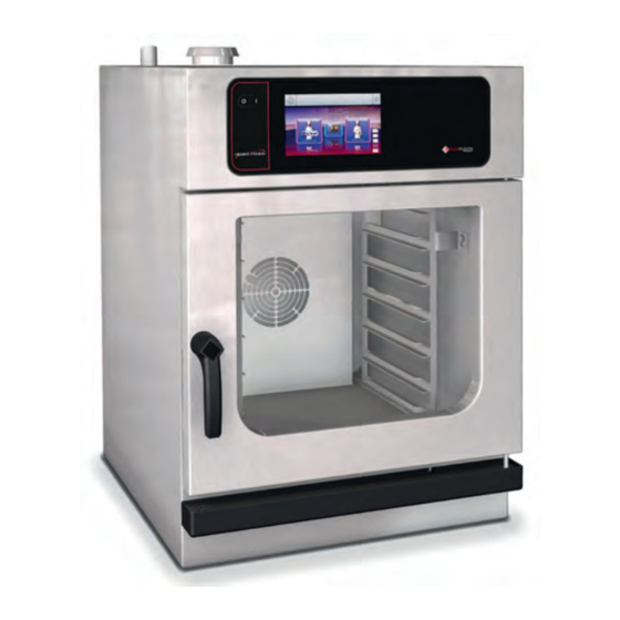
Description of the unit 3 Description of the unit 3.1 Overview of the unit 3.1.1 Tabletop unit Image: Tabletop unit a Operating unit h Core temperature sensor (covered) b Hang-in frame i USB port (covered) c Insulating disk j Nameplate d Cooking chamber door k Housing e Door handle... -
Page 11: Planning Drawing
Description of the unit 3.2 Planning drawing 3.2.1 Tabletop unit Image: Countertop unit Size > 50 50 (1,97) 50 (1,97) (1,97) (21,65) (30,83) (31,14) > 50 50 (1,97) 50 (1,97) (1,97) (21,65) (24,8) (31,14) All dimensions in mm (in) 3.3 Unit and connection data Size Dimensions Unit... - Page 12 Description of the unit Size Protection class IPX5 Type of connection 3PE AC 50/60 Hz, 3NPE AC 50/60 Hz Voltage (V) Connected load (kW) Fuse (A) Voltage (V) Connected load (kW) Fuse (A) Voltage (V) Connected load (kW) Fuse (A) Voltage (V) Connected load (kW) Fuse (A)
- Page 13 Description of the unit Size Fuse (A) Voltage (V) Connected load (kW) Fuse (A) Type of connection 1NPE AC 50/60 Hz Voltage (V) Connected load (kW) Fuse (A) Voltage (V) Connected load (kW) Fuse (A) Voltage (V) Connected load (kW) Fuse (A) Softened drinking water connection Type of water...
- Page 14 Description of the unit Size Temperature-resistant to (°C 95 (203 ) (°F)) Connection (mm (in)) 40 (1,57) Maximum flow rate (l/min (gal/ 10 (2,64) min)) Transformer voltage Type of connection 3NPE / AC 50/60 Hz, 3PE / AC 50/60 Hz Voltage range (V) 208 —...
-
Page 15: 4 Transporting The Unit
Transporting the unit 4 Transporting the unit Risk of property damage and personnel injury from tipping unit CAUTION • Stay clear of lifted unit. • Move lifted unit carefully. Risk of property damage from improper transport NOTICE • Transport the unit upright. •... - Page 16 Transporting the unit 1. Remove the packaging. 2. Pull the protective film off the unit. 3. Remove all packaging material from the cooking chamber. 4. Clean the unit (see "Cleaning and maintaining the unit" in the operating instructions). 5. Enter the information from the nameplate into the Start-up operation report.
-
Page 17: 5 Installing The Unit
Installing the unit 5 Installing the unit Risk of crushing from improper installation CAUTION • Protect the unit and work area during installation and alignment. Risk of fire from failure to observe applicable regional fire preven- CAUTION tion regulations • Observe applicable regional fire prevention regulations. Risk of property damage from overheating of the unit NOTICE •... -
Page 18: Setting Up The Unit On A Work Surface Or Underframe
Installing the unit 5.2 Setting up the unit on a work surface or underframe Danger due to heavy weight of the unit (over 60 kg) CAUTION • Erect the unit with several people. • Raise / lower the unit with suitable lifting equipment. Prerequisite Work surface / underframe must support the weight of the unit Work surface / underframe must be aligned horizontally Underframe must be set up in accordance with the planning drawing... - Page 19 Installing the unit Image: A Stop profile, B Hang-in frame a Stop profile c Hang-in frame b Bolt Prerequisite Pins installed in the uprights of the base frame 1. Place the stop profiles on the pins (at the back). 2. Install the support racks. Installation instructions...
-
Page 20: 6 Connecting The Unit
Connecting the unit 6 Connecting the unit Risk of personal injury and property damage from electric shock DANGER • Before working on the unit, ensure that the unit is dead. • Do not operate the unit with the housing open. Risk of injury from sharp edges CAUTION •... -
Page 21: Removing And Attaching The Unit Cover
Connecting the unit 2. Screw in the screws on the rear panel. The rear panel must be in contact with the unit on all sides. 6.1.2 Removing and attaching the unit cover Removing the unit cover on a tabletop unit Image: Removing the unit cover a Air inlet nozzle d Steam outlet... -
Page 22: Special Wendy´s Installation Requirements
Connecting the unit 6.1.3 Special Wendy´s installation requirements Before connecting the Combi, make sure all components, of the Combi To affix the combi to the wire stand, locate the clamps as seen below. Affix the notched side of the clamp so that the screw can be affixed through the bottom of the back of the unit as seen below. - Page 23 Connecting the unit Find the elbow as seen below and affix it to the left side of the back of the unit. Installation instructions 21 B...
-
Page 24: Attaching The Hygiene Plate
Connecting the unit 6.1.4 Attaching the hygiene plate The hygiene plate is enclosed with the unit. INFORMATION Before the electrical connection is made, guide the lines through the openings in the hygiene plate. Image: Attaching the hygiene plate a Hygiene plate c Threaded cable connection b Rubber buffer d Gland for waste water pipe... - Page 25 Connecting the unit Electrical connection line Minimum requirements for the unit's electrical connection line to the electrical outlet: Connection Electrical connection line Permanent connection for fixed Rubber sheath cable, oil-resistant, installation with a cable from the unit to shrouded and flexible in accordance a separate connection box.
-
Page 26: Adjusting The Unit To The Supply Voltage
Connecting the unit The unit can be connected to a fault current device. If a residual-current circuit breaker is used, the residual-current circuit breaker installed must be type A (RCD type A ) to ensure that AC fault currents and pulsating DC fault currents are detected. Potential equalization Image: Potential equalization symbol The unit can be included in a potential equalization system by means of... - Page 27 Connecting the unit Image: A Transformer T1 location; B Transformer connections for control system Prerequisite Unit dead 1. Use an appropriate meter to measure the supply voltage. The voltage range must match the information on the nameplate. If voltage fluctuations are to be expected, take the maximum expected voltage into account.
-
Page 28: Description Of The Electrical Connection
Connecting the unit 6.2.2 Description of the electrical connection Image: Electrical connection terminal diagram in the unit A, B, C, D Power optimization PE Protective conductor system 13, 14 Potential-free contact X1 Connection to electrical outlet L1, L2, L3 Line conductors X2 Power optimization system connection (POS) N Neutral conductor... -
Page 29: Connecting The Power Optimization System
Connecting the unit Image: Electrical connection line, A Tabletop unit, B Built-in unit a Connection terminals X1 c Threaded cable connection b Electrical connection line d Cover panel for connection terminals Prerequisite Unit dead Electrical connection line dead Unit adjusted to supply voltage Housing opened 1. -
Page 30: Connecting The Potential Equalization
Connecting the unit Image: Connecting the power optimization system a Connection terminals X2 for power c Threaded cable connection optimization system b electrical connection line for power optimization system Prerequisite Unit dead Electrical connection line dead Housing opened 1. Pull the electrical connection line into the unit through the cable gland. -
Page 31: Connecting The Kitchen Guiding System
Connecting the unit 2. Fill out the Start-up operation report. 6.3 Connecting the kitchen guiding system The units can be connected to a kitchen guiding system using an RJ45 plug. Risk of personal injury and property damage from electric shock DANGER •... -
Page 32: Performing The Basic Setting Of The Control
Connecting the unit 6.4 Performing the basic setting of the control Image: Main menu a Main menu d "Unit functions" button b FlexiHelp button e Back button c Language selection 6.4.1 Changing the basic setting of the control By entering the password "2100", the basic setting for the installation can be displayed and changed. -
Page 33: Making The Water Connection
Connecting the unit 6.5 Making the water connection Drinking water installation tasks Drinking water installation tasks on drinking water lines and the unit may only be performed by a specialist company, which is approved by the drinking water utility company in the particular region. The applicable regional regulations, standards and guidelines must be observed, as well as the connection conditions imposed by the drinking water utility company responsible. -
Page 34: Connecting The Drinking Water Connection Line
Connecting the unit 6.5.1 Connecting the drinking water connection line Image: Water connection a Softened drinking water d Drinking water connection b Connection line e Backflow preventer c Softened drinking water f Drinking water connection Prerequisite Water pressure complies with specifications (see "Unit and connection data") Backflow preventer installed Pressure-resistant connection lines suitable for tap water are... -
Page 35: Making The Waste Water Connection
Connecting the unit Image: Connecting softened drinking water to both connections a Backflow preventer d T-piece b Connection line e Seal c Dirt filter f Softened drinking water Prerequisite Water pressure complies with specifications (see "Unit and connection data") Backflow preventer installed Pressure-tight connection line suitable for drinking water is available 1. -
Page 36: Connecting The Waste Water Line To A Permanent Connection
Connecting the unit 6.6.1 Connecting the waste water line to a permanent connection Image: Waste water line to a permanent connection a Waste water connection d Waste water system siphon b Waste water line e Pipe clamp c Waste water system f Vacuum breaker If a siphon is installed in the waste water system, a vacuum breaker must be INFORMATION... -
Page 37: Special Wendy´s Installation Requirements
Installing the unit 6.6.2 Special Wendy´s installation requierements Remove the parts from the Vent Diverter Kit box and make sure you have all parts as seen below 2 screws 1 vent diverter assembly 1 diverter pipe 2 two gaskets 1. Place one gasket on the vent diverter connection. 2. - Page 38 Connecting the unit 34 B Installation instructions...
-
Page 39: 7 Installing The Unit
Installing the unit 7 Installing the unit Danger due to heavy weight of the unit (over 60 kg) CAUTION • Erect the unit with several people. • Raise / lower the unit with suitable lifting equipment. Risk of crushing from improper installation CAUTION •... -
Page 40: 8 Testing The Function
Testing the function 8 Testing the function Risk of personal injury and property damage from unsuccessful DANGER operational check • Do not put the unit into service. • Contact customer service. Prerequisite Electrical connection made Water connection made Waste water connection made Unit cleaned 8.1 Checking the controls 1. -
Page 41: Heating The Unit Up And Rinsing It Out
Putting the unit into service 8.3 Heating the unit up and rinsing it out 1. Switch on the unit. 2. Tap the "Manual cooking" button. The Manual cooking menu is displayed. 3. Run the Steaming cooking mode for 15 minutes at 100 °C. 4. - Page 42 Putting the unit into service Electrical connection Electrical connection made properly? Potential equalization Power optimization system Potential-free contact … Electrical connections made properly? Fault current device connected directly before this unit? Fault current device connected before this and other units? Supply voltage measured? Supply voltage: _______________ (V) Set transformer voltage...
- Page 43 Putting the unit into service Basic setting of the control Power optimization system set? Water filter maintenance set? No maintenance message Maintenance message at: _______________ l (gal) Network configuration set? DHCP IP address: ____________________________ Subnet mask: ____________________________ Gateway: ____________________________ Kitchen guiding system set? Active Disabled Ethernet...
- Page 44 Putting the unit into service Electrical installation was made by: Company Installation fitter Place, date Signature The connection to a kitchen guiding system was made by: Company Installation fitter Place, date Signature Water installation was made by: Company Installation fitter Place, date Signature Wastewater installation was made by:...
- Page 48 Henny Penny Corporation P.O.Box 60 Eaton,OH 45320 Phone +1 937 456-8400 Fax +1 937 456-8402 Toll free in USA Phone +1 937 417-8417 *FM06-066* Fax +1 937 417-8434 www.hennypenny.com Henny Penny Corp., Eaton, Ohio 45320, Revised 2/23/2018...
Need help?
Do you have a question about the FlexFusion SpaceSaver Plus FSE-610 and is the answer not in the manual?
Questions and answers