
Related Manuals for Henny Penny FlexFusion ELECTRIC SPACESSAVER


Summary of Contents for Henny Penny FlexFusion ELECTRIC SPACESSAVER
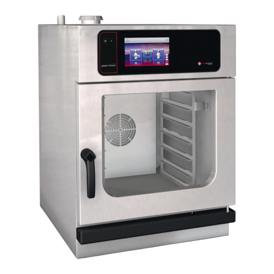
- Page 1 Service-in- structions FlexFusion® ELECTRIC SPACE$SAVER (PLUS) Model FSE-605 FSE-610 3727002-0B- en-US AE-12/15/2022...
- Page 2 Manufacturer Copyright by MKN Maschinenfabrik Kurt Neubauer GmbH & Co. KG Halberstaedter Strasse 2a D-38300 Wolfenbuettel Telephone 0 53 31 / 89-0 Telefax 0 53 31 / 89-280 Service-instructions...
-
Page 3: Table Of Contents
Directory of contents 1 Password overview ............ 7 2 Introduction ................. 8 2.1 About this manual ................ 8 2.2 Warranty .................... 8 3 Safety instructions ............. 9 4 Component overview ............ 10 5 Opening the appliance ............. 13 5.1 Unit cover and rear wall .............. 13 6 Service menu - appliance test ......... 14 6.1 Service menu ... - Page 4 Directory of contents 6.25 Restoring the SD card .............. 37 6.26 Background lighting .............. 37 6.27 Hour meter .................. 37 6.28 Status overview direct access ............ 38 7 Wendy's settings .............. 39 7.1 Call up the device settings menu .......... 39 7.2 Loading settings ................ 40 7.2.1 Enter OEM code .................. 40 7.2.2 Select the cookbook ...
- Page 5 Directory of contents 11.17 5009: The application could not be started. Application is restarting. .................... 72 11.18 5010: The application could not be started. Restore configuration backup? ................. 74 11.19 5013: Application could not be restored! Restore to factory settings with OK. .................. 74 11.20 Unit was restarted after power failure ...
- Page 6 Directory of contents Service-instructions...
-
Page 7: 1 Password Overview
Password overview 1 Password overview Range Passwor Description Described in Installation / 2100 Setting all basic parameters (for Installation commissioning example time / date). instructions Network settings 2000 Input network addressing. Only for Installation units with touchscreen control. instructions Basic settings / user Setting of basic values ... -
Page 8: 2 Introduction
Introduction 2 Introduction 2.1 About this manual This service manual contains information needed by the service technician for professional and correct fault isolation, repair and maintenance of the unit. The service technician must also observe the contents of the installation instructions and the user manual. Target group Target group for this service manual is qualified personnel who are familiar with the technical functioning and operation of the unit. -
Page 9: 3 Safety Instructions
Safety instructions 3 Safety instructions For servicing tasks, the service technician must be familiar with and observe regional regulations. In addition, the notes in the service manual must be observed. Danger to life due to electric current DANGER ü Disconnect power prior to performing gas and electrical work. •... -
Page 10: 4 Component Overview
Component overview 4 Component overview Image: Space$afer Plus - rear view B4 Steaming temperature sensor B5 Temperature sensor - Humidity B14 Pressure switch E1 Heating element G13 Pump for cleaner G14 Pump for rinse aid G16 Circulation pump G24 Drain pump K12 Double solenoid valve K20 Steaming unit M8 Lift magnet... - Page 11 Component overview Image: Space$Safer Plus - Anischt oben Service-instructions...
- Page 12 Component overview A1 Control board A3 Digital key B0 Thermal switch 70°C B2 Cooking room sensor B11 Safety temperature limiter B13 Thermal switch 50°C B15 Reed contact switch (for right- E3 Cooking chamber light hand stop on left-hand side; for left-hand stop on right-hand side) F Fuses 6A inert...
-
Page 13: 5 Opening The Appliance
Opening the appliance 5 Opening the appliance 5.1 Unit cover and rear wall Overview a Rear panel c Unit cover b Air inlet nozzle cover Remove unit cover Remove cover from air inlet nozzles by turning it. Remove the screws from the unit cover. Remove the unit cover. -
Page 14: 6 Service Menu - Appliance Test
Service menu - appliance test 6 Service menu - appliance test 6.1 Service menu Description • Functional testing of individual components • Error analysis • Maintenance • Change basic settings • Software update The graphics shown may deviate due to changes and different software versions. -
Page 15: Appliance Information
Service menu - appliance test 6.2 Appliance information Description Display of the appliance-specific information Software version Cookbook version Unit configuration Serial number Date of last CombiDoctor diagnosis. Contact data Overview Exiting the appliance Touch the Back field. information Service-instructions... -
Page 16: Status Overview
Service menu - appliance test 6.3 Status overview Status 1 Heating circuit PWM: heat requirement in %. POS: power optimization system (option). Temperature sensors B1, B3, B6, B7 are not present. Status 2 Climate control system, fan B14: Pressure switch on the DynaSteam unit PWM: heat requirement in %. -
Page 17: Combidoctor
Service menu - appliance test Status 4 Miscellaneous K3: Manual rinse K10: Activation of the exhaust hood at high speed (option) B15: Reed contact switch K07, K13, K14: Not used Temperature sensors B1, B3, B6, B7 are not present. 6.4 CombiDoctor Description The CombiDoctor offers an automatic check of the climate control and the WaveClean automatic cleaning. - Page 18 Service menu - appliance test Step 3 (heat output) 1. Check of heat output. Display switches to green = test successful. Display switches to red = test not successful. Check of on-site voltage supply. Check of heating element Check of solid-state relay Check of internal fuse for load circuit (depends on unit version).
- Page 19 Service menu - appliance test Step 8 (WaveClean siphon pump) 1. Check of WaveClean siphon pump. Display switches to green = test successful. Display switches to red = test not successful. Check of siphon pump via relay test. A fault is present on the component or the control board.
-
Page 20: Relay Test
Service menu - appliance test 6.5 Relay test Description Separate control of the relay. Testing the relay. Testing the connected components. Relays K1 and K16 are switched on permanently. INFORMATION A plurality of relays are switched on simultaneously. Overview Image: Relay test page 1 Image: Relay test page 2 Activating relay test Touch field of relay to be tested. - Page 21 Service menu - appliance test Relay overview Relay Connect Description Info Main contactor Q1 208V AC POS A 208V AC POS B 208V AC Magnetic valve K23 for manual 208V AC rinse Magnetic valve for water vapor 208V AC elimination K12 Siphon pump G24 208V AC Backup relay K6...
-
Page 22: Waveclean Test
Service menu - appliance test 6.6 WaveClean test Overview Description WaveClean test program for function check. Circulation pump Siphon pump Magnetic valve for water filling Door seal / leak tightness in door area Follow the instructions on the touch screen. INFORMATION The test is used exclusively for functional testing and not to clean the cooking chamber. -
Page 23: 100°C + Core Temperature Calibration
Service menu - appliance test 6.7 100°C + core temperature calibration Description Calibration for cooking chamber sensor and core temperature sensor. Testing the calibration. Performing the calibration. The cooking chamber sensor and core temperature sensor calibration is performed in one step. The units are factory calibrated. -
Page 24: Check Calibration
Service menu - appliance test 6.7.1 Check calibration Prerequisite Calibrated digital temperature measurement device. The temperature in the cooking chamber is < 100°C. Fix internal core temperature sensor and temperature sensor of external measurement device in the cooking chamber. Use a grill rack for this. Point the sensor tips upward in order to prevent measurement errors. -
Page 25: Calibrate Cooking Chamber Sensor
Service menu - appliance test 6.7.2 Calibrate cooking chamber sensor Prerequisite Execute Check calibration and do not switch appliance off. (see „6.7.1 Check calibration‟, Page 24) Temperature display on the touch screen indicates 100°C. Calibration Adjust offset value by adjusting the roller. Let 10 minutes adjustment time elapse. -
Page 26: Dynasteam Test
Service menu - appliance test 6.8 DynaSteam test Description The DynaSteam test allows the function test of the DynaSteam steaming unit. Calibration of the steaming unit is not possible / necessary. Prerequisite Access to the water supply pipe in the cooking chamber. Remove both hook-in points. -
Page 27: Emptying The Water
Service menu - appliance test 6.9 Emptying the water Description Water drainage removes water residue from the unit to prevent frost damage during transport and idle period. Requirement Both water connections are connected to compressed air. The pressure may not exceed 6 bar. The cooking chamber temperature is <... -
Page 28: Audio Settings
Service menu - appliance test 6.11 Audio settings Overview Setting the volume Set the desired volume using the sliders. Touch the "OK" field. Changes saved. Canceling the selection Touch the "Back" field. Service-instructions... -
Page 29: Select Signal Tones
Service menu - appliance test 6.12 Select signal tones Set signal tones Set the profile by adjusting the rollers. Tap the "OK" field. Changes saved. Canceling the selection Tap the "Back" field. 6.13 POS activation Description Software activation for the optional connection to a customer-supplied performance optimization system. -
Page 30: Software Update
Service menu - appliance test 6.15 Software update Description Update of the software via the USB interface. Additional content (help texts, cookbooks, videos) will not be updated. Performing the update Perform according to instructions on the touchscreen and description . Tap the "OK"... -
Page 31: Restoring Data
Service menu - appliance test 6.17 Restoring data Description Import function of parameters stored on the SD card. Import is absolutely essential after the operating panel has been replaced. Restoring data Perform according to instructions on the touchscreen. Touch the Confirmation field. Restoring of the data from the SD card. -
Page 32: Water Filter Maintenance
Service menu - appliance test 6.19 Water filter maintenance Description With use of a water filter on the soft water connection of the unit, a maintenance note may appear after the stored flow quantity has been reached. For this, the appropriate filter capacity must be determined and entered. -
Page 33: Setting Units
Service menu - appliance test 6.21 Setting units Overview To convert the units 1. Select the desired temperature and volume. 2. Touch the "OK" field. 6.22 Backup relay Description The control board has a spare relay, which allows alternative use in case of a relay failure. - Page 34 Service menu - appliance test Relay Connect Description Instruction Main contactor Q1 Reconnect the line from X10.2 to X12.5 and to assign a reserve relay to it. POS A Reconnect the line from X11.1 to X12.5 and to assign a reserve relay to it. POS B Reconnect the line from X11.2 to X12.5 and to assign a reserve relay to it.
-
Page 35: Settings Parameters
Service menu - appliance test 6.23 Settings parameters 6.23.1 Selecting and changing parameters Description Querying and setting additional parameters. Overview Selecting parameters Selecting parameters by adjusting the roller. Tap the "Read" field. Display of set parameters. Changing parameters Use the number block to set the desired values by tapping. Tap the "Write"... - Page 36 Service menu - appliance test Basic setting Standard Range of Explanation value adjustment Controls the cooking chamber 0-60 seconds lamp when closing the cooking chamber door Maximum power outage 100 s 90 – 600 Time within which the cooking program will duration for a warm start seconds continue after interruption of the power supply.
-
Page 37: Backing Up The Sd Card
Service menu - appliance test 6.24 Backing up the SD card Description Export the data from the internal SD card and external USB stick. Backing up the SD card Perform according to instructions on the touchscreen. Touch the Confirmation field. Back-up of the data. -
Page 38: Status Overview Direct Access
Service menu - appliance test 6.28 Status overview direct access Description Direct access in the status overview. Display of all processes and temperature in ongoing operation. Overview Calling up status overview Touch the invisible field three times quickly. Change of the display to the multi-page status overview . Exiting the status overview Touch the Back field. -
Page 39: 7 Wendy's Settings
Wendy's settings 7 Wendy's settings 7.1 Call up the device settings menu Switch on the unit. Tap the "Unit functions" button. Display menu Unit functions . Image 6: "Unit functions" button Ungültiger Pfad '2147011852/2147008011/132614/' Image 7: Unit functions button in the title bar Tap the "Settings"... -
Page 40: Loading Settings
Wendy's settings 7.2 Loading settings 7.2.1 Enter OEM code Overview OEM code OEM Partner OEM code 110201 Prerequisite Menu Settings displayed Wipe to select the page with the "Load OEM settings" field in the left menu area. Tap the "Load OEM settings" field. Enter OEM code and tap Confirm field. -
Page 41: Select The Cookbook
Wendy's settings 7.2.2 Select the cookbook Prerequisite Menu Settings displayed Wipe to select the page with the "Load OEM settings" field in the left menu area. Tap the "Select cookbook" field. Select the cookbook and confirm with OK. Perform unit restart via key On Off . After the restart, the software jumps directly to the Favorites display. -
Page 42: Importing The Manufacturer's Cookbook
Wendy's settings 7.3 Importing the manufacturer's cookbook Overview Importing a cookbook Select setting menu with password "111". Select the page with the "Import manufacturer cookbook" field in the left menu area by swiping. Insert prepared USB stick. On the USB stick, the folder "FCImport" must be unpacked and located on the root directory. -
Page 43: Customize Vapour Deletion
Wendy's settings 7.4 Customize vapour deletion Description Due to regional regulations, the adjustment of the vestibule removal may be necessary. Overview Opening the Service menu 1. Call up the service menu (see „6.1.1 Calling up the service level‟, Page 14). 2. -
Page 44: 8 Software
Software 8 Software 8.1 Software update Prerequisite USB stick. Maximum size 32 GB. FAT formatting (default). The disk should be empty if possible. Current software update. The update is provided as packed ZIP file. Preparing the USB stick Open and download Zip file and unzip. In general, the unzipped folder is in the same directory as the previously compressed one. - Page 45 Software Performing the update Switch on the unit. Tap the "Unit functions" field. Display menu Unit functions . Tap the "Settings" field. Display of window " PIN ". Enter password and touch Confirmation field. The password for the Settings menu is 111. Select the "Software update"...
-
Page 46: Importing Additional Content
Software 8.2 Importing additional content Description Import function for manufacturer contents: • Cookbook graphics • Help information • Sound files Prerequisite USB stick. Maximum size 32 GB. FAT formatting (default). The disk should be empty if possible. Current additional content. Additional contents are provided as packed .ZIP file. - Page 47 Software Importing additional Switch the unit on. content Tap the "Appliance functions" field. Display of Appliance functions menu. Tap "Settings" field. Display of " PIN " window. Enter password and tap the Confirmation field. The password for the Settings menu is 111. Select the field "Import additional contents"...
-
Page 48: Importing The Manufacturer's Cookbook
Software 8.3 Importing the manufacturer's cookbook Prerequisite USB stick. On the unit, the software version 1.29 (from 04/2014) or higher is installed. Check of the software version in the unit's information (see „6.2 Appliance information‟, Page 15). If necessary, perform software update . Preparing the USB stick TouchClassicDB.sdf FCImport... - Page 49 Software Exiting selection Tap the Back field. Service-instructions...
-
Page 50: 9 Trade Show Mode
Trade show mode 9 Trade show mode Description Trade show mode allows appliance operation for demonstration purposes. Prerequisite A single-phase power supply is required for operation. Unit is connected to L3 and N. See also installation instructions. Calling up the selection Switch unit to "I"... -
Page 51: 10 Electronics
Electronics 10 Electronics 10.1 Block diagram for the control 18V AC 230V AC 24V DC CAN X5 230V AC Legend Control board Transformer Control panel Power board Fan motor Digital key Service-instructions... -
Page 52: Control Board
Electronics 10.2 Control board 10.2.1 Layout Service-instructions... -
Page 53: Configuration
Electronics 10.2.2 Configuration Connector X1 Description Input 10.7 V AC for lighting Power supply I/O board 18V AC Connector X2, X3, X4 Not assigned Connector X5 CAN bus line to the motor M10 Connector X6 Not assigned Connector X7 MMI communication Connector X8 Digital key contains device-specific information. - Page 54 Electronics Connector X15 (potential- Description free) Input K13, pump liquid cleaning G13 (208V AC) Output K13, pump liquid cleaning G13 (208V AC) Input K14, pump rinse aid G14 (208V AC) Output K14, pump rinse aid G14 (208V AC) Connector X16 (potential- Not assigned free) Connector X17 (208V AC)
-
Page 55: Safety Overview
Electronics 10.3 Safety overview F4.1 T1-F2 10,7V AC 3,15A 230V AC T1-F1 18V AC 3,15A 230V AC A1-F3 230V AC 3,15A A1-F5 230V AC 3,15A A1-F2 24V DC 3,15A F1, 6A F1.1, 6A Legend Control board Backup relay Operating panel Magnetic valve extinguishing Cooking chamber STL Magnetic valve manual rinse... -
Page 56: 11 Error Messages
Error messages 11 Error messages 11.1 Emergency operation Description In order to allows limited use in case of error, the appliance has various emergency programs. Emergency operation is activated automatically and displayed. After elimination of the error indicated, the controller switches back into regular operation automatically. A reset is not necessary. -
Page 57: Cooking Chamber Sensor Defective (694, 695)
Error messages 11.2 Cooking chamber sensor defective (694, 695) Description Emergency operation is activated automatically and displayed. The core temperature sensor takes over the function of the cooking chamber sensor. Cooking program with core temperature sensor is no longer available. Troubleshooting Function check The measurement values can be called up in the status overview. -
Page 58: Water Vapor Sensor Defective (710)
Error messages Is the wire or the test prod damaged physically? Remove existing core temperature sensor from the control board A1, X24 and plug in new core temperature sensor. Error eliminated? Replace control board. Replace core temperature sensor. 11.4 Water vapor sensor defective (710) Description In the event of an error, emergency operation is activated and displayed automatically. -
Page 59: Excess Temperature In The Cooking Chamber (Id18, Id73)
Error messages 11.5 Excess temperature in the cooking chamber (ID18, ID73) Description The measured temperature in the cooking chamber is outside the allowable range of more than 310°C. The unit is no longer operational until the cooking chamber cools down. The measurement is taken by the cooking chamber sensor, core temperature sensor and the moisture sensor. -
Page 60: Overtemperature Control (Tmp_Id2)
Error messages 11.6 Overtemperature control (TMP_ID2) Description The temperature sensor on the control board is measuring a temperature of >75°C (167°F). The unit is no longer operational until it cools down. Troubleshooting With software version 1.71, the temperature threshold was increased from 70°C (158°F) to 75°C (175°F). -
Page 61: Risk Of Frost (Tmp_Id72)
Error messages 11.7 Risk of frost (TMP_ID72) Description The unit is not ready for use. The temperature sensor on the control board is measuring a temperature of <0°C. Troubleshooting Increase the room temperature and switch on unit again. Change location of the unit. Service-instructions... -
Page 62: Fan Defective Or Temperature Limiter Triggered (702)
Error messages 11.8 Fan defective or temperature limiter triggered (702) Description The control board A1 does not receive any response via the CAN bus cable from fan motor M10. There is an error in the safety circuit or fan area. 208V AC Control pcb A1 3,15A... - Page 63 Error messages Troubleshooting Switch unit on and measure voltage at main contactor Q1, terminals A1 and A2. Is voltage present at the main contactor (208 V) and is it energized (switched on)? No voltage present. There is an error in the STL Voltage present.
- Page 64 Error messages Continued from previous page Does the fault appear only sporadically? Update software to version 1.69 or higher. Check thermal switch B0 and cooling fan for proper operation. Make sure that the air intake area is not dirty. Error eliminated? Replace communication cable between motor control and motor for test purposes and perform test run.
-
Page 65: Fan Defective. Cooking Program Was Cancelled (701)
Error messages 11.9 Fan defective. Cooking program was cancelled (701) Description Description The control board A1 does not receive any response via the CAN bus cable from fan motor M10 when the fan is active. Troubleshooting Fan defective or temperature limiter triggered (702) Service-instructions... -
Page 66: Fan_Id23: Fan Error: Attempt To Restart
Error messages 11.10 FAN_ID23: Fan error: Attempt to restart Description The control board A1 does not receive any response regarding speed from fan motor M10. There is either a problem with the 320 V voltage supply from the power board or a fault in the fan. Troubleshooting Switch off unit and restart. -
Page 67: Water Pressure Too Low (709)
Error messages 11.11 Water pressure too low (709) Description The error message appears when the pressure switch registers insufficient water pressure. This is a notification that does not result in interruption of the cooking program. a Pressure switch c Water supply pipe in the cooking chamber b Sieve Troubleshooting... - Page 68 Error messages Soft water connection attached and water valve at site open? Connect water supply or open water valve. Is the fault message displayed continuously? Check sieve on the water connection for soiling. To Check the on-site water pressure while observing do this, remove the on-site water connection to the nearby water consumers.
-
Page 69: Water Pressure During Waveclean Too Low
Error messages 11.12 Water pressure during WaveClean too low Description Description This fault message is displayed if the pressure switch registered a water pressure that is too low during WaveClean's. The program is stopped until the water pressure is sufficiently high again. Troubleshooting Ensure on-site water supply to soft water connection of unit. -
Page 70: Failure To Access External Eeprom (Sof_Id12)
Error messages 11.13 Failure to access external EEPROM (SOF_ID12) Description It is not possible to access the digital key (EEPROM). Troubleshooting Make sure that the digital key is oriented correctly and inserted fully. The side with the hole must point to the sensor connections. Control board defective. -
Page 71: Faulty Can Connection
Error messages 11.14 Faulty CAN connection Description There is a communication fault between the operating panel and control panel. In addition, temperature sensor and fan fault messages appear on the touchscreen. Troubleshooting Replace communication cable between operating panel and control panel circuit board. Replace control board. - Page 72 Error messages 11.17 5009: The application could not be started. Application is restarting. Description The software does not boot. There is a fault in the communication or the software is damaged. Troubleshooting Confirm the message with " OK ". The software is restarted. The error may appear twice.
- Page 73 Error messages Troubleshooting takes place by disconnecting individual CAN bus connections. Other error messages are generated in the process. The decisive factor is that the original message "5009 or 5010" is no longer displayed. Disconnect CAN bus cable between control board and motor.
- Page 74 Error messages 11.18 5010: The application could not be started. Restore configuration backup? Description Starting the software is not possible because of an error. The system will attempt to restore the configuration. Troubleshooting Confirm message. An automatic restore starts. Next, update the software. If the error continues to appear, the operating panel needs to be replaced.
- Page 75 Error messages Check that the "On/Off" switch functions properly and is in the correct position. The switch must be fastened securely. The switch is available separately. Check the electrical connections and screw connections in the area of the mains connection terminal, transformer and power line to the control board (connector X1).
- Page 76 Error messages Service-instructions...
- Page 80 Manufacturer Copyright by MKN Maschinenfabrik Kurt Neubauer GmbH & Co. KG Halberstaedter Strasse 2a D-38300 Wolfenbuettel Telephone 0 53 31 / 89-0 Telefax 0 53 31 / 89-280 *3727002-0B- AE-12/15/2022* Henny Penny Corp., Eaton, Ohio 45320, Revised 12/19/2022...
Need help?
Do you have a question about the FlexFusion ELECTRIC SPACESSAVER and is the answer not in the manual?
Questions and answers