
Subscribe to Our Youtube Channel
Related Manuals for US Water Systems Synergy 9000


Summary of Contents for US Water Systems Synergy 9000
- Page 1 US Water Synergy 9000, 9100, 9500 Installation Manual 163-SS | 093-CWS-075 | 093-CWS-100 | 140-95...
-
Page 2: Table Of Contents
Table of Contents Unpacking and Inspection ..................3 Safety Guide ...................... 3 Proper Installation ..................... 4 Specifications ......................5 Equipment Configuration ................... 9 Before Starting Installation ..................10 Tools, Pipe, Fittings, and Other Materials ............10 Job Specification Sheet ................... 10 How the Water Softener Works ................ -
Page 3: Unpacking And Inspection
Be sure to check the entire unit for any shipping damage or lost parts. Also note damage to the shipping cartons. Contact US Water Systems at 1-800-608-8792 to report any shipping damage within 24 hours of delivery. Claims made after 24 hours may not be honored. -
Page 4: Proper Installation
Proper Installation This water softening system must be properly installed and located in accordance with the Installation Instructions before it is used or the warranty will be void. • Do not Install or store where it will be maximum. Use a pressure reducing valve exposed to temperatures below freezing (PRV) to reduce the pressure. -
Page 5: Specifications
Specifications US Water Synergy Alternating Water Softener Programming (Fleck 9100) Abbreviation Parameter Display Format Valve Type dF/1b Control Type FI (Immediate Regen) Number of Tanks Tank in Service U1 or U2 (info only) Residential Synergy Residential (9100) Model Number 163-SS-10 163-SS-15 163-SS-20 163-SS-25... - Page 6 US Water Commercial Twin Alternating Water Softener Programming Abbrevia- Parameter Selection tion Display Format Valve Type dF/1b Control FI (Immediate Regen) Type Number of Tanks Tank in U1 or U2 (info only) Service Commercial US Water 3/4" Commercial (9100) Model Number 093- 093- 093-...
- Page 7 US Water Commercial Alternating Water Softener Programming (Fleck 9000) Abbreviation Parameter Display Format Valve Type dF/1b Control Type FI (Immediate Regen) Number of Tanks Tank in Service U1 or U2 (info only) Commercial US Water 1" Commercial (9000) Model Number 093- 093- 093-...
- Page 8 US Water Commercial Alternating Water Softener Programming (Fleck 9500) Abbreviation Parameter Display Format Valve Type dF/1b Control Type FI (Immediate Regen) Number of Tanks Tank in Service U1 or U2 (info only) Commercial US Water 1.5" Commercial (9500) Model Number 140-95-120 140-95-150 140-95-210...
-
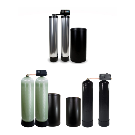
Page 9: Equipment Configuration
Equipment Configuration 9000 / 9100 Equipment Configuration 9500 Equipment Configuration Need help? 1.800.390.5936 www.uswatersystems.com... -
Page 10: Before Starting Installation
Before Starting Installation Tools, Pipe, Fittings, and Other Materials • Channel Locks • ALWAYS install the included bypass valve or install a 3 shut-off valve hard • Screwdriver piped bypass. Bypass valves allow the • Teflon Tape water to be turned off to the but can still •... -
Page 11: How The Water Softener Works
How the Water Softener Works Water hardness is derived from Calcium and Magnesium minerals that have been dis- solved into the water under the earth’s surface. These minerals are found in limestone deposits and are the source of hard water. The amount of hardness in a given water supply is dependent upon the quantity of Calcium and Magnesium present and the length of time water has been in contact with them. - Page 12 Backwash - The control valve directs the water flow in a reverse direction through the mineral tank, separating the resin beads and flushing any accumulated particles to a waste drain. Brine & Rinse - In the first part of this cycle, the control valve directs brine sol- ution downward through the mineral tank, driving-off collected hardness ions and replenishing the resin beads with sodium ions.
-
Page 13: Where To Install The Softener
Where to Install the Softener • Place the softener as close as possible to • Put the softener in a place where water the pressure tank (well system) or water damage is least likely to occur if a leak meter (city water). develops. -
Page 14: Softener Preparation
Softener Preparation Softener Tank Preparation Water Pressure: A minimum of 20 pounds of water pressure is required for the regenera- tion valve to operate effectively. Electrical Facilities: An uninterrupted alternating current (AC) supply is required. Note: Other voltages are available. Please make sure your voltage supply is compatible with your unit before installation. - Page 15 Use the funnel provided to pour the softening resin into the resin tank. Pour it evenly around the hole to ensure it is well distributed in the tank and pour slow enough to keep from plugging the hole. A helper may be needed to hold the funnel during the filling process.
- Page 16 Lubricate the distributor O-ring and tank O-ring seal on the control valve. Install the upper basket by pushing in the slotted holes and turning it clockwise until it locks in place. Repeat these steps for the auxiliary tank adaptor. Need help? 1.800.390.5936 www.uswatersystems.com...
- Page 17 Place the main control valve on one tank and the tank adapter on the second tank. Place the valve or adaptor over the distributor tube through the bottom of the upper basket. Slide the valve or adaptor down and thread the valve on the tank by turning it clockwise.
- Page 18 Connect the two tanks using the interconnect plumbing. 9000 Model: Install O-rings on all four connection points on the interconnect tubing. Lubricate the O-rings and make sure they are not twisted. Slide the interconnect tubes in the valve assembly and secure them using the retaining clips. Tighten the clips once the tubes are installed.
- Page 19 Slide the interconnect tubes in the valve assembly and tank adaptor. Then secure them using the retaining clips. Tighten the clips once the tubes are installed. When all four clips are in place, the tanks are connected. It is recommended that a mini- mum of 1"...
- Page 20 NOTE: These tubes should be level when installation is complete. If the tubes are not level or in a bind, a leak could occur at the O-ring seals. If one tank is higher than the other, the lower tank must be shimmed to ensure the interconnect tubes are level.
- Page 21 10. Attach the plumbing according to local codes. 9100 Model:The inlet and outlet pipes will attach to the 1" female threads on the by- pass valve. The bypass valve will be labeled with arrows. The inlet port will have an arrow pointing toward the unit and the outlet will have an arrow pointing away from the unit.
- Page 22 9500 Model: The inlet and outlet plumbing will be connected to the 1 1/2" female connections on the unit. A three valve bypass should be plumbed in to bypass the unit, if necessary. The external meter will thread into the outlet port on the valve. There are arrows stamped in the plumbing connection points that indicate the inlet and outlet connections.
- Page 23 13. Once the fittings are installed and tight, push the 5/8" drain line on the barb and secure it using a hose clamp. This tube should be attached to a sanitary drain. An air gap fitting should be installed on the drain pipe where this tube will be connected (check local codes).
-
Page 24: Brine Tank Installation
Brine Tank Installation NOTE: Be sure the floor under the salt storage tank is clean and level. Any debris can cause a leak when the tank is weighed down with salt and brine solution. Connect the supplied 3/8" tubing to both brine connections. At the control valve, place the nut over the tube and install the brass sleeve in the tube. - Page 25 Now connect the brine line to the brine tank safety float assembly. Remove the brine tank lid and the brine well cap. There is a red clip on the cap that will be used to hold the brine line in place. Remove it, and the tape holding it, and put it to the side. Then push the brine line through the brine tank and brine well.
- Page 26 Need help? 1.800.390.5936 www.uswatersystems.com...
-
Page 27: System Start-Up
System Start-Up Place the unit in the bypass position. There is a pointer on the bypass valve handle. This pointer should be pointing to "bypass" on the valve. When the bypass valve is in the bypass position, the handle will bisect the plumbing connections. Turn on the main water supply. -
Page 28: Control Valve Features
Control Valve Features NOTE: Make all electrical connections according to codes. Tank one (or U1) has the control valve and tank two (or U2) has the adapter. There are indicators showing which position the control valve is in during regeneration and which tank is in service on the right side of the gear assembly. - Page 29 The extra cycle button serves as an enter / return button when programming. The up and down arrows allow value changes in each parameter programming mode. Once the value is reached, the extra cycle button can be pushed to save the value and move to the next parameter.
- Page 30 Entering Master Programming Mode Set the Time of Day display to 12:01 P.M. Press the Extra Cycle button (to exit Setting Time of Day mode). Then press and hold the Up and Down buttons together until the programming icon replaces the service icon and the Display Format screen appears. Exiting Master Programming Mode Press the Extra Cycle button to accept the displayed settings and cycle to the next parameter.
-
Page 31: Sxt Programming
SXT Programming NOTE: The highlighted values are the selections that should be made. Some pa- rameters will refer to the settings chart for values. Display Format (Display Code DF) This is the first screen that appears when entering Master Programming Mode. The Display Format setting specifies the unit of measure that will be used for volume and how the control will display the Time of Day. - Page 32 Control Type (Display Code CT) Press the Extra Cycle button. Use this display to set the Control Type. This specifies how the control determines when to trigger regeneration. For details on how the var- ious options function, refer to the "Timer Operation" section of this service manual. This option setting is identified by "CT"...
- Page 33 Unit Capacity (Display Code C) Press the Extra Cycle button. Use this display to set the Unit Capacity. This setting specifies the treatment capacity of the system media. Enter the capacity of the media bed in grains of hardness when configuring a softener system and in the desired volume capacity when configuring a filter system.
- Page 34 Feed Water Hardness (Display Code H) Press the Extra Cycle button. Use this display to set the feed water hardness. Enter the feed water hardness in grains per unit volume for softener systems, or 1 for filter systems. This option setting is identified by "H" in the upper left hand corner of the screen.
- Page 35 Fixed Reserve Capacity (Display Code RC) Press the Extra Cycle button. Use this display to set the Reserve Capacity. This setting specified a fixed volume that will be held as a reserve. The reserve capacity cannot be set to a value greater than one half of the calculated system capacity. The reserve capacity is a fixed volume and does not change if the unit capacity or feedwater hardness is changed.
- Page 36 11. Regeneration Time Press the Extra Cycle button. Use this display to set the Regeneration Time. This setting specifies the time of day the control will initiate a delayed, manually queued, or day override triggered regeneration. This option setting is identified by "RT" in the upper left hand corner of the screen.
- Page 37 12. Regeneration Cycle Step Times Press the Extra Cycle button. Use this display to set the Regeneration Cycle Step Times. The different regeneration cycles are listed in sequence based on the valve type selected for the system and are identified by an abbreviation in the upper left hand corner of the screen.
- Page 38 13. Flow Meter Type (Display Code FM) Press the Extra Cycle button. Use this display to set the type of flow meter connec- ted to the control. This option setting is identified by "FM" in the upper left hand corner of the screen. Use the Up and Down buttons to select one of the 7 available settings: t0.7 Fleck 3/4"...
- Page 39 Use this display to adjust the Day Override. This option setting is identified by "DO" in the upper left hand corner of the screen. Press the Extra Cycle button. Use this display to adjust the Regeneration Time. This option setting is identified by "RT" in the upper left hand corner of the screen. Press the Extra Cycle button.
-
Page 40: Diagnostics And Troubleshooting
Diagnostics and Troubleshooting Diagnostic Programming Mode Options Abbreviation Parameter Description Flow Rate Displays the current outlet flow rate Peak Flow Rate Displays the highest flow rate measured since the last regeneration Hours in Service Displays the total hours that the unit has been in service Volume Used Displays the total volume of water treated by the unit Reserve Capacity... - Page 41 Press the Up button. Use this display to view the Volume Used since the last regen- eration cycle. This option setting is identified by "VU" in the upper left hand corner of the screen. Press the Up button. Use this display to view the Reserve Capacity. This option setting is identified by "RC"...
- Page 42 Problem Cause Correction 1. Water conditioner fails to Electrical service to unit has Ensure permanent electrical service regenerate been interrupted (check fuse, plug, pull chain, or switch) Control is defective Replace control Power failure Reset time of day 2. Hard water Bypass valve is open Close bypass valve No salt is in brine tank...
- Page 43 Problem Cause Correction Internal control leak Change seals, spacers, and piston as- sembly Service adapter did not cycle Check drive motor and switches 9. Control cycles continuous- Misadjusted, broken, or shor- Determine if switch or timer is faulty ted switch and replace it or replace complete power head 10.
-
Page 44: Control Dimensions
Control Dimensions 9000 Series Control Need help? 1.800.390.5936 www.uswatersystems.com... - Page 45 9100 Series Control Need help? 1.800.390.5936 www.uswatersystems.com...
- Page 46 9500 Series Control Need help? 1.800.390.5936 www.uswatersystems.com...
-
Page 47: Water Conditioner Flow Diagrams
Water Conditioner Flow Diagrams Need help? 1.800.390.5936 www.uswatersystems.com... - Page 48 Need help? 1.800.390.5936 www.uswatersystems.com...
-
Page 49: Wiring Diagram
Wiring Diagram 9000 / 9500 Series Valves Need help? 1.800.390.5936 www.uswatersystems.com... -
Page 50: Warranty
When properly installed Five Year Valve and Electronics Guaran- and maintained, it will give years of trouble tee - US Water Systems will replace any free service. part on the valve or electronics which fails Model Numbers Covered: 163-SS... - Page 51 Five Year Valve and Electronics Guaran- humidity or heat will not be covered under tee - US Water Systems will replace any warranty. part on the valve or electronics which fails within five years from date of manufacture,...
Need help?
Do you have a question about the Synergy 9000 and is the answer not in the manual?
Questions and answers