Table of Contents
Advertisement
Quick Links
Advertisement
Table of Contents

Related Manuals for US Water Systems Maverick Lite Commercial 200 GPD


Summary of Contents for US Water Systems Maverick Lite Commercial 200 GPD
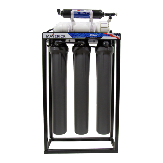
- Page 1 Maverick Lite Commercial RO System - 200 to 750 GPD 220-MAV-XXX...
-
Page 2: Table Of Contents
Table of Contents Unpacking and Inspection ..................3 Safety Guide ...................... 3 Proper Installation ..................... 4 How the System Works ..................... 5 Specifications ......................6 Rejection, Recovery & Flow Rates ................8 Component Identification ..................9 Filter Installation Instructions ................... 10 Membrane Installation, Removal &... -
Page 3: Unpacking And Inspection
Be sure to check the entire unit for any shipping damage or lost parts. Also note damage to the shipping cartons. Contact US Water Systems at 1-800-608-8792 to report any shipping damage within 24 hours of delivery. Claims made after 24 hours may not be honored. -
Page 4: Proper Installation
Proper Installation This RO system must be properly installed and located in accordance with the Installation Instructions before it is used or the warranty will be void. • DO NOT install or store where the sys- • Maximum allowable inlet water pressure tem will be exposed to temperatures be- is 125 psi. -
Page 5: How The System Works
How the System Works A pressurized water source is fed to the first pre-filter which is a 5 micron spun poly sediment filter. The water then passes through the sediment filter to the carbon block filter and then on to the chloramine carbon block filter. Water passes through the carbon block filters and then on to the membrane filters via an automatic shut off (ASO) valve. -
Page 6: Specifications
Specifications Design 200 GPD 350 GPD 500 GPD 750 GPD Configuration Single Pass Feed Water Source TDS < 1000 Standard Recovery Rate Rejection and Flow Rates Nominal Salt Rejection % 97.5 Permeate Flow gpm 0.13 0.24 0.35 0.52 Concentrate Flow gpm 0.39 0.21 0.35... - Page 7 Design 200 GPD 350 GPD 500 GPD 750 GPD Maximum pH (Continuous) Minimum pH (Continuous) Maximum Turbidity NYU * If any of the feed water parameters are not within the limits given, contact US Water Systems for assistance. NOTE: HIGHER TDS AND / OR LOWER TEMPERATURES WILL REDUCE THE SYS- TEMS PRODUCTION.
-
Page 8: Rejection, Recovery & Flow Rates
Rejection, Recovery & Flow Rates The Maverick reverse osmosis system is designed to produce permeate water at the capacities indicated by the suffix in the systems name under the conditions listed above. The amount of total dissolved solids (TDS) rejected by the membrane is expressed as a percentage. -
Page 9: Component Identification
Component Identification NOTE: 200 GPD and 750 GPD Maverick Systems have an additional membrane added to their components support.uswatersystems.com www.uswatersystems.com... -
Page 10: Filter Installation Instructions
Filter Installation Instructions Looking at the side of the system with the system label, remove the left filter sump. This is the Sediment filter housing. Grease the O-rings on the sump and the sedi- ment filter. Place the filter in the sump and place it under the filter top. Push the filter up into the filter top and make sure it is seated fully. -
Page 11: Membrane Installation, Removal & Replacement
Membrane Installation, Removal & Replacement Replacing and installing membranes in the pressure vessels is an easy process if you have the proper information and tools at hand. Please refer to the following instructions when removing and replacing membrane elements. Remove the end cap from the membrane housings. This is done by removing the 3/8"... - Page 12 Make sure that all parts are clean and free from dirt. Examine the brine seal and permeate tube for nicks or cuts. Replace the cap O-rings or membrane brine seal if damaged. Lubricate the O-rings on the new membrane. Flow directions should be observed for installation of the membrane element into the pressure vessel.
- Page 13 Install the membrane in the housing and be sure that it is fully seated in the housing. When the membrane is fully seated, the permeate tube on the membrane should be inset from the housing. Once the membrane is seated, the cap can be re-installed and the tube attached. The membrane is now installed.
- Page 14 Replacing the Membrane Element Remove the membrane cap from the membrane housing. Turn the cap counterclock- wise while securing the membrane housing. Once the cap is removed, long nose pliers may be necessary to pull the old membrane element out of the membrane element housing.
-
Page 15: Ro Tank Installation
RO Tank Installation Remove the RO tank from its packaging and place it in the desired location. Thread tape the port at the bottom of the tank and install the reinforced coupling. Tighten it hand tight then, with a pair of channel locks, tighten it further. Use a second pair of channel locks to stabilize the pipe and ensure damage does not occur. - Page 16 Install the QC x MNPT fitting into the previously installed reducing bushing. Ensure the threads are thread taped and tighten it hand tight. Use an adjustable wrench to tighten it further. Connect the supplied 3/8" green tubing to the previously installed QC fitting. Using a pair of tube cutters, make a cut along the line and install the supplied 3/8"...
-
Page 17: System Installation
System Installation Check all system components and ensure tubing is fully seated and fittings are tight. If a tank was purchased, remove the stem fitting from the post carbon filter tee and attach the previously installed green line. Ensure that the ball valve is shut off. Connect the 3/8"... - Page 18 Connect the concentrate 1/4" tubing (waste) line from the flow restrictor to a drain. Convey the 3/8" blue permeate line to a drain to dispose of the initial flushing water from the membrane. Proceed to plug the booster pump into an appropriate outlet, if appropriate. Turn on the feed water.
- Page 19 Once the system has been flushed and the TDS level has stabilized, the permeate / product line can be attached to distribution system. Additional flushing of the distribu- tion system may be required to reach the TDS level that is produced directly after the RO system at all points of use.
-
Page 20: Operation And Maintenance
Operation and Maintenance The reverse osmosis process causes a concentration of impurities. The impurities may precipitate (come out of solution) when their concentration reaches saturation levels. NOTE: PRECIPITATION CAN SCALE OR FOUL MEMBRANES AND MUST BE PRE- VENTED. Periodically observe the quality and quantity of product water from the system NOTE: CHECK THE FEED WATER PRESSURE GOING INTO THE REVERSE OS- MOSIS MEMBRANE. -
Page 21: Service Assistance
Service Assistance If service assistance is required, please complete the following process: Contact US Water Systems. Prior to making the call, have the following information available: system installation date, current operating parameters (e.g. flow, operating pressures, pH, etc.) and a detailed description of the problem. -
Page 22: System Flow Diagram
System Flow Diagram support.uswatersystems.com www.uswatersystems.com... - Page 23 support.uswatersystems.com www.uswatersystems.com...
- Page 24 support.uswatersystems.com www.uswatersystems.com...
- Page 25 support.uswatersystems.com www.uswatersystems.com...
-
Page 26: Electrical Schematic
Electrical Schematic support.uswatersystems.com www.uswatersystems.com... -
Page 27: Troubleshooting
Troubleshooting Symptoms Possible Causes Corrective Action Low Inlet Pressure Low supply pressure Increase inlet pressure Pre-filters plugged Change filters Leaks Fix any visible leaks Low Permeate Flow Cold feed water See temperature correction sheet Low operating pressure See low inlet pressure Defective membrane brine seal Inspect and / or replace brine seal Fouled or scaled membrane... -
Page 28: Warranty
OLIS, IN 46234 (800) 608-USWA. ANY Five Year Warranty on RO Storage Tanks IMPLIED WARRANTIES OF FITNESS OR - US Water Systems, Inc. warrants that for MERCHANTABILITY ARE LIMITED TO five (5) years from the date of purchase, THE TERMS OF THIS EXPRESSED WAR-...
Need help?
Do you have a question about the Maverick Lite Commercial 200 GPD and is the answer not in the manual?
Questions and answers