Table of Contents
Advertisement
Quick Links
Advertisement
Table of Contents

Related Manuals for US Water Systems Raptor


Summary of Contents for US Water Systems Raptor
- Page 1 Raptor Light Commercial Reverse Osmosis System 220-USW-RPT-XXX...
-
Page 2: Table Of Contents
Table of Contents Unpacking and Inspection ..................3 Safety Guide ...................... 3 Proper Installation ..................... 4 Introduction ....................... 5 How the System Works ..................... 6 Specifications ......................7 System Flow Diagram ....................8 Component Identification ..................10 Rejection, Recovery & Flow Rates ................12 Filter Installation Instructions ................... -
Page 3: Unpacking And Inspection
Be sure to check the entire unit for any shipping damage or lost parts. Also note damage to the shipping cartons. Contact US Water Systems at 1-800-608-8792 to report any ship- ping damage within 24 hours of delivery. Claims made after 24 hours may not be honor- ed. -
Page 4: Proper Installation
Proper Installation This RO system must be properly installed and located in accordance with the Installation Instructions before it is used or the warranty will be void. • DO NOT install or store where the sys- • Maximum allowable inlet water pressure tem will be exposed to temperatures be- is 125 psi. -
Page 5: Introduction
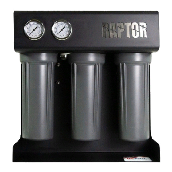
Professional-Grade Raptor RO outperforms the field with quality and longevity. The 500 - 750 GPD Raptor RO can sit on a counter, shelf, or the floor. Its steel powder coated frame is corrosion-proof and the system utilizes three stages of filtration ahead of the membrane. -
Page 6: How The System Works
How the System Works A pressurized water source is fed to the first pre-filter which is a 5 micron sediment filter. The water then passes through a GAC and catalytic carbon filter to the solenoid shutoff valve. The water then goes from the solenoid switch to the booster pump. Water is pres- surized at the booster pump and then is conveyed to the membranes. -
Page 7: Specifications
Specifications Design 500 GPD 750 GPD Configuration Single Pass Feed Water Source TDS < 1000 ppm Rejection and Flow Rates Rejection 97 - 98.5% Permeate Flow Rate 0.35 GPM 0.52 GPM Connections Feed 3/8" Permeate 3/8" Concentrate 1/4" Tank Connection 3/8"... -
Page 8: System Flow Diagram
System Flow Diagram Need help? 1.800.390.5936 www.uswatersystems.com... - Page 9 Need help? 1.800.390.5936 www.uswatersystems.com...
-
Page 10: Component Identification
Component Identification Need help? 1.800.390.5936 www.uswatersystems.com... - Page 11 Need help? 1.800.390.5936 www.uswatersystems.com...
-
Page 12: Rejection, Recovery & Flow Rates
NOTE: ALL TDS FIGURES MUST BE EXPRESSED IN THE SAME UNITS, TYPICALLY PARTS PER MILLION (PPM) OR MILLIGRAMS PER LITER (MG/L). The Raptor reverse osmosis system is designed to reject up to 98.5% NaCl, unless com- puter projections have been provided or stated otherwise. -
Page 13: Filter Installation Instructions
Filter Installation Instructions Remove the left filter sump. This is the Sediment filter housing. Grease the O-rings on the sump and the sediment filter. Need help? 1.800.390.5936 www.uswatersystems.com... - Page 14 Place the filter in the sump and place it under the filter top. Need help? 1.800.390.5936 www.uswatersystems.com...
- Page 15 Push the filter up into the filter top and make sure it is seated fully. Install the filter sump and tighten hand tight. Need help? 1.800.390.5936 www.uswatersystems.com...
- Page 16 Remove the center filter sump. This is the Granular Activated Carbon filter housing. Grease the O-rings on the sump and the carbon filter. Need help? 1.800.390.5936 www.uswatersystems.com...
- Page 17 Place the filter in the sump and place it under the filter top. Push the filter up into the filter top and make sure it is seated fully. Install the filter sump and tighten hand tight. Need help? 1.800.390.5936 www.uswatersystems.com...
- Page 18 Remove the right filter sump. This is the Chloramine carbon pre filter housing. Grease the O-rings on the sump and the carbon filter. Need help? 1.800.390.5936 www.uswatersystems.com...
- Page 19 Place the filter in the sump and place it under the filter top. Need help? 1.800.390.5936 www.uswatersystems.com...
- Page 20 Push the filter up into the filter top and make sure it is seated fully. Install the filter sump and tighten hand tight. Need help? 1.800.390.5936 www.uswatersystems.com...
-
Page 21: Membrane Installation, Removal & Replacement
Membrane Installation, Removal & Replacement Replacing and installing membranes in the pressure vessels is an easy process if you have the proper information and tools at hand. Please refer to the following instructions when removing and replacing membrane elements. WARNING: ALL PRESSURE GAUGES MUST READ ZERO BEFORE PROCEEDING. BEFORE ATTEMPTING, DISCONNECT THE POWER FROM THE SYSTEM AND BLEED ALL WATER PRESSURE FROM THE SYSTEM! 1. - Page 22 3. Make sure that all parts are clean and free from dirt. Examine the brine seal and per- meate tube for nicks or cuts. Replace the cap O-rings or membrane brine seal if dam- aged. Lubricate the O-rings on the new membrane. 4.
- Page 23 5. Install the membrane in the housing and be sure that it is fully seated in the housing. When the membrane is fully seated, the permeate tube on the membrane should be inset from the housing. 6. Once the membrane is seated, the cap can be re-installed and the tube attached. In- stall the lock clip.
- Page 24 Replacing the Membrane Element 1. Remove the membrane cap from the membrane housing. Turn the cap counterclock- wise while securing the membrane housing. Once the cap is removed, long nose pli- ers may be necessary to pull the old membrane element out of the membrane ele- ment housing.
-
Page 25: System Installation
System Installation 1. Inspect the system for any damage that could have occurred during shipment. Al- though all systems have been individually inspected, complete a quick inspection of the fittings, tubing and other components. 2. Please provide a reasonable amount of space for installation and leave 18 inches of space in front of the filter housings for easy removal during maintenance endeavors. - Page 26 5. Connect the 3/8" tank line to the storage tank. If an atmospheric tank is used then leave this port plugged. 6. Connect the faucet or other device to the pure water connection. If an atmospheric tank is used, connect the inlet tubing for the tank to the pure water connection. Con- vey this line to a drain during start up then attach it.
-
Page 27: Start Up Procedure
Start Up Procedure 1. Turn on the feed water and plug the booster pump transformer into a power supply of 110 volts 60 Hz. 2. Dispose of the initial product / permeate (clean) water until the TDS level / conductivi- ty of the product water stabilizes at the lowest (cleanest) value. -
Page 28: Filter Replacement Instructions
Filter Replacement Instructions 1. Unplug the RO system, shut off the water supply and release the pressure on the system. Both gauges on the system should show 0 psi. 2. Remove each filter and sump and discard the old filter. Remove any excess water from the sump as well. -
Page 29: Operation And Maintenance
Operation and Maintenance The reverse osmosis process causes a concentration of impurities. The impurities may precipitate (come out of solution) when their concentration reaches saturation levels. NOTE: PRECIPITATION CAN SCALE OR FOUL MEMBRANES AND MUST BE PRE- VENTED. 1. Periodically observe the quality and quantity of product water from the system NOTE: CHECK THE FEED WATER PRESSURE GOING INTO THE REVERSE OS- MOSIS MEMBRANE. - Page 30 Service Assistance If service assistance is required, please complete the following process: Contact US Water Systems. Prior to making the call, have the following information avail- able: system installation date, current operating parameters (e.g. flow, operating pres- sures, pH, etc.) and a detailed description of the problem.
-
Page 31: Temperature Correction Factors For Membranes
Temperature Correction Factors For Membranes Find the temperature correct factor (TCF) from the table below. Divide the rated permeate flow at 77°F by the temperature correction factor. The result is the permeate flow at the desired temperature. Temper- Tem- Temper- Tem- Temper- Tem-... - Page 32 If a system is rated to produce 5 GPM of permeate water at 77°F, the same system will produce more water at a higher temperature. It will also produce less water at a lower temperature. Use the temperature correction table to obtain the correct flow. Need help? 1.800.390.5936 www.uswatersystems.com...
-
Page 33: Troubleshooting
Troubleshooting Symptoms Possible Causes Corrective Action Low Inlet Pressure Low supply pressure Increase inlet pressure Pre-filters plugged Change filters Solenoid valve malfunction Replace sol. valve and / or coil Motor may not be drawing correct Use clamp-on amp meter to check the mo- current tor amp draw Leaks... -
Page 34: Warranty
US caused by strike, government regulations or Water Raptor RO system, US Water Sys- other circumstances beyond the control of tems, Inc warrants the following: US WATER SYSTEMS, INC. .
Need help?
Do you have a question about the Raptor and is the answer not in the manual?
Questions and answers