Table of Contents
Advertisement
Quick Links
Visit us online at
www.uswatersystems.com
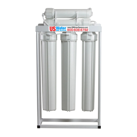
US Water 200 GPD Floor-Mount Light
Commercial Economy RO System
Owners Manual
Models:
220-USCRO-200FR
REVISION #
1.0
REVISION DATE
April 13, 2015
US Water Systems Corporate Office
1209 Country Club Road
Indianapolis, IN 46234
1-800-608-8792
info@uswatersystems.com
Advertisement
Table of Contents

Related Manuals for US Water Systems 220-USCRO-200FR


Summary of Contents for US Water Systems 220-USCRO-200FR
- Page 1 Visit us online at www.uswatersystems.com US Water 200 GPD Floor-Mount Light Commercial Economy RO System Owners Manual Models: 220-USCRO-200FR US Water Systems Corporate Office 1209 Country Club Road Indianapolis, IN 46234 1-800-608-8792 REVISION # info@uswatersystems.com REVISION DATE April 13, 2015...
-
Page 2: Table Of Contents
Be sure to check the entire system for any shipping damage or parts loss. Also note damage to the shipping cartons. Contact US Water Systems at 1-800-608-8792 to report any shipping damage within 24 hours of de- livery. Claims made after 24 hours may not be honored. -
Page 3: Proper Installation
Introduction The US Water Systems 200 GPD Light Commercial Floor Mount RO System is an economical solution for a light commercial RO system need. Industrial systems that can produce 200 GPD are typically three times the cost as this economy model. The 200 GPD floor mount RO system utilizes three 20”... -
Page 4: Operation Overview And Parameters
Operating Parameters Operating Parameters Feed Water Requirements **If any of the feed water parameters are not within the limits given, consult US Water Systems for assistance. Feed Temperature 40 - 85°F System Inlet Pressure 30 - 80 PSIG Maximum Operating Pressure (@77°F) -
Page 5: System Safety
US Water Systems 200 GPD Economy Reverse Osmosis Systems are designed to produce permeate water at the capacities indicated by the suffix in the system’s name under the aforementioned conditions. For example, the US Water Systems 200 GPD Reverse Osmosis System produces 200 gallons per day of permeate water at the listed operating test conditions. -
Page 6: System Components And Connections
System Components and Connections Membrane Housings Feed Water Connection... - Page 7 System Components and Connections Membrane Housings Flow Restrictor Automatic Shutoff Valve (ASO) Drain Permeate/ Connection Product Water Connection...
-
Page 8: System Dimensions
System Dimensions... -
Page 9: System Installation And Start-Up Instructions
System Installation and Start-up Instructions 1. Install the membranes in the membrane housings. By removing the 1/4” tubing from the cap side fittings. 2. Remove the membrane caps by turning them counterclockwise. BE SURE not to loose the O-rings when re- moving the caps. - Page 10 System Installation and Start-up Instructions 1. Inspect the system for any damage that could have occurred during shipment. Although all systems have been individually inspected, complete a quick inspection of the fittings, tubing and other components. 2. Please provide a reasonable amount of space for installation. NOTE: THE REVERSE OSMOSIS SYSTEM SHOULD BE INSTALLED INDOORS AND IT IS SUGGESTED THAT IT NOT BE IN DIRECT SUNLIGHT OR EXTREME COLD.
- Page 11 System Installation and Start-up Instructions 5. Convey the 1/4” permeate line to a drain to dispose of the initial flushing water from the membrane. This line will be attached to the tank later in the startup process. Permeate Line to Tank or Point of Use.
- Page 12 Pressure Tank Configuration...
- Page 13 Atmospheric Tank Configuration...
-
Page 14: Specifications
Specifications Parameter Value DESIGN Configuration Single Pass Feed Water Source TDS <1000 ppm REJECTION AND FLOW RATES Rejection 97-98.5 % Permeate Flow Rate 0.13 GPM CONNECTIONS Feed 1/4” Permeate 1/4” Concentrate 1/4” Operating Limits Design Temperature 77° F Max. Turbidity NTU Max. -
Page 15: Operation And Maintenance
If service assistance is required, please complete the following process: Contact US Water Systems. Prior to making the call, have the following information available: system installation date, current operating parameters (e.g. flow, operating pressures, pH, etc.) and a detailed description of the... -
Page 16: Flow Diagram
Flow Diagram... -
Page 17: Troubleshooting Guide
Troubleshooting Guide SYMPTOMS POSSIBLE CAUSES CORRECTIVE ACTION Low supply pressure Increase inlet pressure Pre-filters plugged Change filters Solenoid valve malfunction Replace sol. valve and/or coil Use clamp-on amp meter to check Low Inlet Pressure Motor may not be drawing correct current the motor amp draw. -
Page 18: Warranty
RO system. No responsibility is assumed for delays or failure to meet these warranties caused by strike, government regulations or other circumstances beyond the control of US WATER SYSTEMS, INC.. To obtain warranty service, call or write: US WATER SYSTEMS, INC. 1209 Country Club Road Indianapolis, IN 46234 (800) 608- USWA.
Need help?
Do you have a question about the 220-USCRO-200FR and is the answer not in the manual?
Questions and answers