Icom IC-F6062 Instruction Manual
Uhf/vhf mobile transceiver
Hide thumbs
Also See for IC-F6062:
- Operating manual (50 pages) ,
- Service manual (37 pages) ,
- Instruction manual (24 pages)
Table of Contents
Advertisement
Quick Links
Advertisement
Table of Contents

Related Manuals for Icom IC-F6062


Summary of Contents for Icom IC-F6062
- Page 1 INSTRUCTION MANUAL VHF MOBILE TRANSCEIVER iF5062 UHF MOBILE TRANSCEIVER iF6062...
-
Page 2: Important
NEVER instruction manual contains important operating instructions connect the transceiver to a power source of more for the IC-F5062 and IC-F6062 VHF/UHF MOBILE TRANS- than 16 V DC such as a 24 V battery. This connection will ruin CEIVERS. the transceiver. -
Page 3: Table Of Contents
TABLE OF CONTENTS IMPORTANT ..................i AVOID operating the transceiver without running the vehi- EXPLICIT DEFINITIONS ..............i cle’s engine. The vehicle’s battery will quickly run out if the PRECAUTIONS ................i transceiver transmits while the vehicle’s engine OFF. TABLE OF CONTENTS ..............ii AVOID 1 PANEL DESCRIPTION ............ -
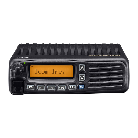
Page 4: Panel Description
PANEL DESCRIPTION I Front panel Function display (p. 2) Speaker I c o m I n c . q AF VOLUME CONTROL KNOB [VOL] y MICROPHONE CONNECTOR Rotate the knob to adjust the audio output level. Connect the supplied or optional microphone. •... -
Page 5: I Function Display
PANEL DESCRIPTION I Function display y BELL INDICATOR Appears/blinks when the specific 2/5-tone/BIIS* /MDC* code is received, according to the pre-programming. u CALL CODE MEMORY INDICATOR ➥ Appears when the call code memory is selected. I c o m I n c . ➥... -
Page 6: I Programmable Function Keys
[P0], [P1], [P2], [P3] and [P4] programmable function keys. When the power ON scan function is turned ON; Consult your Icom dealer or system operator for details con- Push to pause scanning, then resumes scanning after a cerning your transceivers programming. - Page 7 PANEL DESCRIPTION PRIO A/B KEYS PUBLIC ADDRESS KEY ➥ Push to select Priority A or Priority B channel. Push to activate the Public Address (PA) function for voice ➥ Push and hold [Prio A (Rewrite)] or [Prio B (Rewrite)] to set amplification.
- Page 8 PANEL DESCRIPTION HIGH/LOW KEY SCRAMBLER FUNCTION Push to select the transmit output power temporarily or per- Push to toggle the voice scrambler function ON and OFF. manently, depending on the pre-setting. • Ask your dealer for the output power level for each selection. CALL KEYS Push to transmit a 2/5-tone/BIIS ID code.
- Page 9 PANEL DESCRIPTION TX CODE ENTER KEY (PMR or BIIS PMR operation only) USER SET MODE KEY ➥ Push and hold to enter user set mode. Push to enter the ID code edit mode directly, for both 5-tone • During user set mode, push this key to select an item, and and MSK.
-
Page 10: Basic Operation
BASIC OPERATION I Turning power ON I Channel selection q Push [ ] to turn the power ON. Several types of channel selections are available. Methods w If the transceiver is programmed for a start up password, may differ according to your system set up. input the digit codes as directed by your dealer. -
Page 11: I Call Procedure
BASIC OPERATION I Call procedure I Receiving and transmitting When your system employs tone signaling (excluding CTCSS Receiving: q Push [ and DTCS), the call procedure may be necessary prior to voice ] to turn the power ON. transmission. The tone signalling employed may be a selec- w Push [CH Up] or [CH Down] to select a channel, in tive calling system which allows you to call specific station(s) sequence. -
Page 12: D Transmitting Notes
BASIC OPERATION D Transmitting notes D TX code channel selection • Transmit inhibit function If the transceiver has [TX Code CH Select] assigned to it, the The transceiver has several inhibit functions which restrict indication can be toggled between the operating channel transmission under the following conditions: number (or name) and TX code channel number (or name). -
Page 13: D Tx Code Number Edit
BASIC OPERATION D TX code number edit (PMR or BIIS PMR operation only) USING [TX CODE ENTER] KEY: If the transceiver has [TX Code CH Select] or [TX Code q After pushing [TX Code CH Select], push [CH Up] or [CH Enter] assigned to it, TX code contents can be edited within Down], or push [TX Code CH Up] or [TX Code CH Down] the allowable digits. -
Page 14: D Dtmf Transmission
BASIC OPERATION I Scrambler function D DTMF transmission If the transceiver has [DTMF Autodial] assigned to it, the auto- matic DTMF transmission function is available. Up to 8 DTMF The voice scrambler function provides private communication channels are available. between stations. The frequency inversion type is equipped to all versions, moreover, the optional Rolling or Non-rolling q Push [DTMF Autodial]—... -
Page 15: I User Set Mode
BASIC OPERATION I User set mode e Push and hold [ User set mode is accessed with [User Set Mode] and allows ] for 1 sec. to turn power OFF, then ON you to set seldom-changed settings. In this case you can again to exit set mode. -
Page 16: Connection And Maintenance
CONNECTION AND MAINTENANCE I Rear panel connection q ANTENNA CONNECTOR w D-Sub 25-pin Antenna Connects to an antenna. Connect an exter- Contact your dealer about nal unit. antenna selection and e EXTERNAL placement. Optional speaker SPEAKER JACK Connect a 4–8 Microphone external speaker. -
Page 17: I Supplied Accessories
CONNECTION AND MAINTENANCE I Supplied Accessories I Mounting the transceiver The universal mounting bracket supplied with your transceiv- Microphone Microphone hanger Microphone er allows overhead mounting. and screw set hanger cable • Mount the transceiver securely with the 4 supplied screws to a thick surface which can support more than 1.5 kg. -
Page 18: I Antenna
CONNECTION AND MAINTENANCE I Antenna I Options A key element in the performance of any communication sys- • RMK-3 + OPC-609 SEPARATION KIT SEPARATION CABLE tem is an antenna. Contact your dealer about antennas and Allows you to install the transceiver main unit separately the best places to mount them. -
Page 19: Doc
EN 300 219-2 (March 2001) Signature vi) EN 300 113-2 (April 2002) CE Versions of the IC-F5062 and IC-F6062 This warning symbol indicates that this equipment which display the “CE” symbol on the serial operates in non-harmonised frequency bands... - Page 20 EN 300 086-2 (March 2001) v) EN 300 219-2 (March 2001) Signature vi) EN 300 113-2 (April 2002) About e-marking: Detailed installation notes for Icom mobile transceivers to be fitted into vehicles are available. Please contact your Icom dealer or distributor.
- Page 21 MEMO...
- Page 22 MEMO...
- Page 23 MEMO...
- Page 24 < Intended Country of Use > A-6566D-1EU-q Printed in Japan © 2007 Icom Inc. 1-1-32 Kamiminami, Hirano-ku, Osaka 547-0003, Japan Printed on recycled paper with soy ink.
Need help?
Do you have a question about the IC-F6062 and is the answer not in the manual?
Questions and answers