Icom IC-F5062 Instruction Manual
Vhf/uhf mobile transceiver
Hide thumbs
Also See for IC-F5062:
- Instruction manual (24 pages) ,
- Operating manual (50 pages) ,
- Servise manual (50 pages)
Table of Contents
Advertisement
Quick Links
Advertisement
Table of Contents

Subscribe to Our Youtube Channel
Related Manuals for Icom IC-F5062


Summary of Contents for Icom IC-F5062
- Page 1 INSTRUCTION MANUAL VHF MOBILE TRANSCEIVER iF5062 UHF MOBILE TRANSCEIVER iF6062...
-
Page 2: Important
RWARNING! NEVER connect the transceiver to a for the IC-F5062 and IC-F6062 VHF/UHF MOBILE TRANS- power source of more than 16 V DC such as a 24 V battery. CEIVERS. This connection will ruin the transceiver. -
Page 3: Table Of Contents
■ Rear panel connection ............14 ■ Supplied Accessories ............16 Icom optional equipment is designed for optimal perform- ■ Mounting the transceiver ............16 ance when used with this transceiver. We are not respon- ■ Antenna .................17 sible for the transceiver being damaged or any accident ■... -
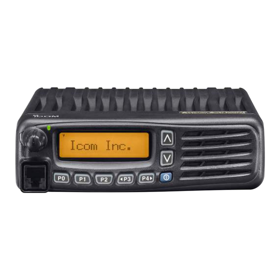
Page 4: Panel Description
PANEL DESCRIPTION ■ Front panel Function display (p. 2) Speaker I c o m I n c . q AF VOLUME CONTROL KNOB [VOL] y MICROPHONE CONNECTOR Rotate the knob to adjust the desired audio output level. Connect the supplied or optional microphone. •... -
Page 5: Function Display
PANEL DESCRIPTION ■ Function display u CALL CODE MEMORY INDICATOR ➥ Appears when the call code memory is selected. ➥ Appears when a phone call is received.* I c o m I n c . i SCROLL INDICATOR Appears when the SDM, includes more than 12 charac- ters, is selected during the received message selection mode* o SDM INDICATOR... -
Page 6: Programmable Function Keys
The following functions can be assigned to [UP], [DOWN], [P0], [P1], [P2], [P3] and [P4] programmable function keys. Push to select an operating zone. Consult your Icom dealer or system operator for details con- SCAN A KEY cerning your transceivers programming. - Page 7 PANEL DESCRIPTION SCAN ADD/DEL (TAG) KEY MONI (AUDI) KEY ➥ Push to add or delete the selected channel to/from the ➥ Push to mute and release the CTCSS (DTCS) or 2-tone scan group. squelch mute. Open any squelch/deactivate any mute 1.
- Page 8 PANEL DESCRIPTION RX SPEAKER KEY TONE/RAN CH SELECT KEY ➥ While in analog mode operation, push to enter the con- Push to turn the RX speaker function ON or OFF. When the RX speaker function is turned ON, the received tinuous tone channel selection mode.
- Page 9 PANEL DESCRIPTION TALK AROUND KEY EMERGENCY KEY Push to turn the talk around function ON and OFF. Push and hold to transmit the emergency call. • The talk around function equalizes the transmit frequency to the • The emergency call transmits with beeps; the display does not receive frequency for transceiver-to-transceiver communication.
- Page 10 PANEL DESCRIPTION TX CODE CHANNEL UP/DOWN KEYS USER SET MODE KEY ➥ Push and hold for 1 sec. to enter user set mode. Push to select a TX code channel directly. • During user set mode, push this key to select an item, and change the value or condition using push [CH Up]/[CH Down].
-
Page 11: Basic Operation
BASIC OPERATION ■ Turning power ON ■ Channel selection q Push and hold [ ] for 1 sec. to turn the power ON. Several types of channel selections are available. Methods w If the transceiver is programmed for a start up password, may differ according to your system set up. -
Page 12: Call Procedure
BASIC OPERATION ■ Call procedure ■ Receiving and transmitting Receiving: When your system employs tone signaling (excluding q Push and hold [ CTCSS and DTCS), a call procedure may be necessary ] for 1 sec. to turn the power ON. w Push [CH Up] or [CH Down] to select the conventional prior to voice transmission. - Page 13 BASIC OPERATION D Transmitting notes D TX code channel selection • Transmit inhibit function If the transceiver has [TX Code CH Select] assigned to it, The transceiver has several inhibit functions which restrict the indication can be toggled between the operating channel transmission under the following conditions: number (or name) and TX code channel number (or name).
- Page 14 BASIC OPERATION D TX code number edit (PMR operation only) If the transceiver has [TX Code CH Select] or [TX Code USING [TX CODE ENTER] KEY: q Push [TX Code Enter] to enter the TX code edit mode. Enter] assigned to it, TX code contents can be edited within •...
-
Page 15: User Set Mode
BASIC OPERATION ■ User set mode e Push [P0] several times to select the appropriate item. User set mode is accessed with [User Set Mode] and allows you to set seldom-changed settings. In this case you can Then, push [Up] or [Down] to set the desired level/condi- tion. -
Page 16: Scrambler Function
BASIC OPERATION ■ Scrambler function ■ Stun function The voice scrambler function provides private communi- When the specified ID, set as a kill ID, is received, the stun cation between stations. The frequency inversion type is function is activated. equipped to all versions, moreover, the optional Rolling or When the kill ID is received, the transceiver switches to the Non-rolling type can be available. -
Page 17: Connection And Maintenance
CONNECTION AND MAINTENANCE ■ Rear panel connection D For mobile operation ANTENNA CONNECTOR D-Sub 25-pin Antenna Connects to an antenna. Contact your deal- Connect an external unit. Optional er about antenna selection and placement. speaker EXTERNAL SPEAKER JACK Connect a 4–8 external speaker. Microphone R C AU T I O N ! N E V E R remove the fuse-holder... - Page 18 CONNECTION AND MAINTENANCE ■ Rear panel connection (Continued) D For base station operation To antenna Microphone ANTENNA CONNECTOR EXTERNAL SPEAKER JACK DC power IGNITION LEAD Connect a 4–8 ø supply 13.2 V D-Sub 25-pin external speaker. Connect an external unit. DC POWER to an Optional speaker...
-
Page 19: Supplied Accessories
CONNECTION AND MAINTENANCE ■ Supplied Accessories ■ Mounting the transceiver The universal mounting bracket supplied with your trans- Microphone Microphone hanger Microphone ceiver allows overhead mounting. and screw set hanger cable • Mount the transceiver securely with the 4 supplied screws to a thick surface which can support more than 1.5 kg. -
Page 20: Antenna
CONNECTION AND MAINTENANCE ■ Antenna ■ Options A key element in the performance of any communication • RMK-3 + OPC-609 SEPARATION KIT SEPARATION CABLE systems is an antenna. Contact your dealer about antennas Allows you to install the transceiver main unit separately and the best places to mount them. - Page 21 EN 300 113-2 v1.3.1 (December 2003) vii) EN 301 166-2 v1.1.1 (December 2001) CE Versions of the IC-F5062 and IC-F6062 This warning symbol indicates that this equip- which display the “CE” symbol on the serial ment operates in non-harmonised frequency...
- Page 22 EN 300 219-2 v1.1.1 (March 2001) Signature EN 300 113-2 v1.3.1 (December 2003) vii) EN 301 166-2 v1.1.1 (December 2001) About e-marking: Detailed installation notes for Icom mobile transceivers to be fitted into vehicles are available. Please contact your Icom dealer or distributor.
- Page 23 MEMO...
- Page 24 < Intended Country of Use > A-6566D-1EU-w Printed in Japan © 2007–2008 Icom Inc. 1-1-32 Kamiminami, Hirano-ku, Osaka 547-0003, Japan Printed on recycled paper with soy ink.
Need help?
Do you have a question about the IC-F5062 and is the answer not in the manual?
Questions and answers