Table of Contents

Related Manuals for Sutter Instrument LAMBDA 10-B


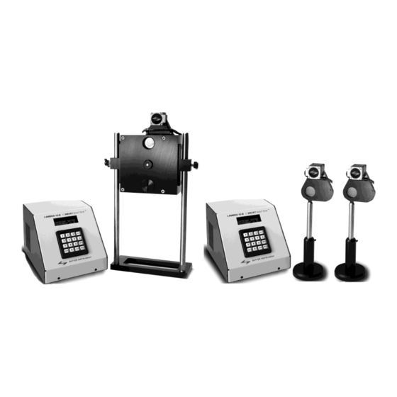
Summary of Contents for Sutter Instrument LAMBDA 10-B
- Page 1 LAMBDA 10 ® Optical Filter Changer and Smart Shutter Control System ® Operation Manual Rev. 1.20Q (20230227) One Digital Drive Novato, CA 94949 Voice: 415-883-0128 Web: www.sutter.com Fax: 415-883-0572 Email: info@sutter.com...
- Page 2 Copyright © 2023 Sutter Instrument Company. All Rights Reserved. LAMBDA 10 ® and SmartShutter ® are registered trademarks of Sutter Instrument Company. LAMBDA 10-B OPERATION MANUAL – REV. 1.20Q (20230227)
- Page 3 LAMBDA 10-B OPERATION MANUAL – REV. 1.20Q (20230227)
- Page 4 (This page intentionally blank.) LAMBDA 10-B OPERATION MANUAL – REV. 1.20Q (20230227)
-
Page 5: Safety Warnings And Precautions
Electrical ▪ Operate the LAMBDA 10-B using 110-120 V AC, 60 Hz, or 220-240 V AC., 50 Hz line voltage. This instrument is designed for connection to a standard laboratory power outlet (Overvoltage Category II), and because it is a microprocessor-controlled device, it should be accorded the same system wiring precautions as any 'computer type' system. -
Page 6: Optical Radiation
▪ The SmartShutter is Not a Safety Shutter: Sutter Instrument Co.’s SmartShutter is not intended to be a ‘safety shutter.’ A safety shutter usually closes automatically in the event of a power failure and is designed with the primary goal of ensuring that it will not allow any unintended exposure. - Page 7 Operate only in a location where there is a free flow of fresh air on all sides. ◼ NEVER ALLOW THE FREE FLOW OF AIR TO BE RESTRICTED. LAMBDA 10-B OPERATION MANUAL – REV. 1.20Q (20230227)
- Page 8 (This page intentionally blank.) LAMBDA 10-B OPERATION MANUAL – REV. 1.20Q (20230227)
-
Page 9: Table Of Contents
1.6.3.1 Keypad ..........................13 1.6.3.2 Display ..........................14 1.7 Functional Description ........................14 1.7.1 Stepping Motor Operation ...................... 14 2. INSTALLATION ..........................17 2.1 Unpacking ............................17 2.2 Pre-Installation Considerations ....................18 LAMBDA 10-B OPERATION MANUAL – REV. 1.20Q (20230227) - Page 10 4.2 Main Status Screen ......................... 33 4.2.1 Filter Wheel/Shutter Configuration ..................33 4.3 Dual-SmartShutter Configuration ....................33 4.4 Placing LAMBDA 10-B into Local Mode ..................34 4.5 Immediate Key Control of Attached Devices ................34 4.5.1 Filter Wheel and/or Shutter Configuration ................34 4.6 Main Menu (F1) ..........................
- Page 11 7. EXTERNAL USB INTERFACE CONTROL ................63 7.1 Installation Steps ..........................64 7.2 Installing the LAMBDA 10-B as a USB Device on a Windows System using the Standard Device Driver ............................65 7.3 Installing the LAMBDA 10-B as a USB Device on a Windows System using CDM (Combined Driver Model) Device Driver ........................
- Page 12 7.4 Installing the USB interface for non-Windows systems ............. 68 7.5 Verifying USB Communication between Remote Computer and LAMBDA 10-B ....68 7.6 Uninstalling the USB Driver for the LAMBDA 10-B ..............69 7.7 Remote Commands and the USB Interface ................. 69 7.8 Command Sequence Formatting and Protocol: ................
- Page 13 Figure 2-7. Assembly order of filter holder parts................. 24 Figure 2-8. Filter ports (plug is removed from the loading port)............25 Figure 3-1. LAMBDA 10-B Cabinet (rear view)..................29 Figure 3-2. Switch, fuse, and power connection................... 29 Figure 3-3.
- Page 14 Table F-9. “Get Controller Type and Configuration” command return data in a wheel & shutter configuration........................... 97 Table F-10. Get Controller Type and Configuration” command return data in a dual- SmartShutter configuration....................97 LAMBDA 10-B OPERATION MANUAL – REV. 1.20Q (20230227)
-
Page 15: General Information
1. GENERAL INFORMATION 1.1 Introduction The LAMBDA 10-B is a filter wheel and shutter control system designed for the rapid change and aperture control of wavelength and is comprised of two subsystems: 1) a controller, and 2) a combination of filter wheels and shutters that are placed in the optical pathway(s) of your existing experimental setup. -
Page 16: Filter Wheel
The following instructions are meant to help you set up the LAMBDA 10-B and become familiar with the manual mode of filter selection. Other sections of this manual contain detailed discussions on the functionality of the controller, how filters are installed, and setting up remote control communications. -
Page 17: Supported Filter Wheel And Shutter Configurations
Figure 1-3. Lambda-series 25mm filter wheel housing with 25mm SmartShutter and 32mm filter wheel housing with 35mm SmartShutter. 1.3.1.1 Supported Filter Wheel and Shutter Configurations The LAMBDA 10-B controller supports two basic filter wheel and/or shutter configurations: 1. Any combination of one filter wheel and one shutter: One standalone filter wheel only (no shutter) One standalone filter wheel and one standalone SmartShutter LAMBDA 10-B OPERATION MANUAL –... -
Page 18: Filter Wheel And Shutter Configurations Not Supported
When a LAMBDA 10-B Filter Wheel system is purchased, its configuration may include one filter wheel, with or without a shutter. If the LAMBDA 10-B system is purchased with a 10- position 25mm (1-inch) filter wheel, you may wish to exchange the filter wheel with a 10- position 32mm or a 5-position 50mm filter wheel. -
Page 19: Mechanical Description
10. Shutter housing 1.3.3 Filters The LAMBDA 10-B Controller can be used with a range of filter wheels. Most of these wheels accept both 25 mm and 1-inch diameter filters. When larger filters are required, a wheel is available that accepts 32 mm diameter filters. -
Page 20: Filter Wheel Adapters
Most microscopes, cameras, light sources and other optical instruments to which the LAMBDA 10-B Filter Wheel may be interfaced will require some sort of adapter to link the devices. Adapters for interfacing the Filter Wheel to most instruments are available from Sutter Instrument Company or can be custom built by Sutter. -
Page 21: Cables
Most microscopes, cameras, light sources, and other optical instruments to which the LAMBDA 10-B Filter Wheel may be interfaced will require some sort of adapter to link the devices. Adapters for interfacing the Filter Wheel to most instruments are available from Sutter Instrument Company or can be custom built by Sutter Instrument. -
Page 22: Figure 1-4. 25Mm Smartshutter Standalone And Mounted On The Housing Of A 25Mm Filter Wheel
More detailed discussions on the controller functions, installation of filters, and remote communications are found in other sections of this manual. Figure 1-4. 25mm SmartShutter standalone and mounted on the housing of a 25mm filter wheel. LAMBDA 10-B OPERATION MANUAL – REV. 1.20Q (20230227) -
Page 23: Modes
In this mode the user selects the extent to which the shutter ◼ opens. When used with the Sutter Instrument light guide system (LLG), this allows the light output from the light guide to be attenuated without changing its wavelength or spatial distribution. -
Page 24: Opening And Closing Times
For a complete opening of 144 steps, the time to open and the time to close will each be about 38 msec. The time required will be approximately proportional to the number of steps, or about 2.6 msec per 10 steps. LAMBDA 10-B OPERATION MANUAL – REV. 1.20Q (20230227) -
Page 25: Repetition Rates And Duty Cycle
APPENDIX A: Stepping Motor Operation. 1.6.2 Rear Panel Connectors All electrical connections are all made on the rear panel of the LAMBDA 10-B. See the FIRST TIME USE chapter for details on connecting the power cord and filter wheel cable(s). -
Page 26: Figure 1-7 Rear Panel Electrical Connections
FILTER WHEEL WITH UNIBLITZ SHUTTER – A 15 pin, DSUB connector used to link the LAMBDA 10-B controller with the filter wheel (and UNIBLITZ shutter, if installed). USB PORT – A USB Type B receptacle used to connect the LAMBDA 10-B controller as a USB device to a USB port of a host computer. -
Page 27: Front Panel Controls
Figure 1-8. LAMBDA 10-B front panel controls. 1.6.3.1 Keypad There are 16 keys on the LAMBDA 10-B keypad. Numerical keys 0 to 9: These keys are used to manually select filter positions and, with the # key, to choose between the eight pre-set speeds... -
Page 28: Display
This causes the poles of the electromagnet to reverse, establishing a force for continued rotation. This switching action is called commutation. LAMBDA 10-B OPERATION MANUAL – REV. 1.20Q (20230227) - Page 29 The motor used in the LAMBDA 10-B has 200 steps per revolution (1.8 degrees per step). There are usually two windings in the stator and reversing the current on one of the windings produces a single step of rotation.
- Page 30 (This page intentionally blank.) LAMBDA 10-B OPERATION MANUAL – REV. 1.20Q (20230227)
-
Page 31: Installation
SmartShutters are to be configured, then a 25-pin cable split to two 9-pin cables is included. The 25-pin end of the cable connects to the LAMBDA 10-B controller, and the longer 9-pin split connects to the first SmartShutter (Shutter A). If only one SmartShutter is used, the second (shorter) 9-pin split is affixed with a terminator (supplied with the cable). -
Page 32: Pre-Installation Considerations
The second individual filter holder and one position of the wheel (position #1) contain only retainers and spacers. The LAMBDA 10-B is shipped to you in a prefabricated foam mold. Please take note of this method of packaging. Should it ever be necessary to ship the LAMBDA 10-B to another location, the same method of packaging should be employed. -
Page 33: Installing The Filter Wheel
In such cases, it may be better to couple the LAMBDA 10-B to the microscope with a flexible light guide. Contact Sutter Instrument for detail of our light-guide adapter system. -
Page 34: Filter Wheel Assembly
Figure 2-2. Filter wheel-mounting stand. 3. IMPORTANT: Make sure that the LAMBDA 10-B controller has its power turned OFF before connecting any of the filter wheels or any of standalone SmartShutters to the controller! Once the controller has been turned off, connect the controller and filter wheel with the appropriate cable provided. -
Page 35: Loading Filters
There are at least two components installed into each filter cup or holder before the LAMBDA 10-B is shipped: A threaded retaining ring to secure the filter into the cup (or holder), and a spacer ring. In all but one of the filter cups, and in one of the filter holders, there will also be a blanking disc. -
Page 36: Figure 2-4. Filter Holder Components
The purpose of the two slots is for the removal and installation of the retaining ring when using the retaining ring driver or spanner wrench that is provided with the LAMBDA 10-B (shown in Figure 2-4). Note how the design of the spanner wrench differs between 25-, 32-, and 50-mm filter sizes. -
Page 37: Installation Of Filters Into Filter Holders
The following procedures describe this process and should be practiced with a drop-in (or slide-in) filter holder before attempting to load filters into the filter cups. Figure 2-5. Changing filters in the Slide-In Filter Holder. LAMBDA 10-B OPERATION MANUAL – REV. 1.20Q (20230227) -
Page 38: Figure 2-6. Removing The Retaining Ring
Next, install the spacer ring into the filter holder. Unless the filter thickness precludes the use of the spacer ring (see Figure 2-6 and Figure 2-7), always install the spacer. This helps to LAMBDA 10-B OPERATION MANUAL – REV. 1.20Q (20230227) -
Page 39: Installation Of Filters Into Filter Cups
LOADING PORT is illustrated in Figure 2-8. Filter position at optical port Filter position at loading port Figure 2-8. Filter ports (plug is removed from the loading port). LAMBDA 10-B OPERATION MANUAL – REV. 1.20Q (20230227) -
Page 40: Filter Loading Tips
We strongly urge that the discs be used. Please be careful and avoid the possibility of direct visualization of high intensity light. 2.6.3 Neutral Density Filters The individual filter holders are typically used for neutral density filters and are installed as described above. LAMBDA 10-B OPERATION MANUAL – REV. 1.20Q (20230227) -
Page 41: Shutter Options
2.7 Shutter Options The LAMBDA 10-B can drive a wheel-mounted shutters or one or two standalone SmartShutters. If wheel-mounted shutter, the shutter can be either a Sutter Instrument SmartShutter or a Uniblitz shutter; whereas if two SmartShutters, then no filter wheels is allowed. - Page 42 (This page intentionally blank.) LAMBDA 10-B OPERATION MANUAL – REV. 1.20Q (20230227)
-
Page 43: Operations
The power switch is located on the rear panel as shown in the figure. The LAMBDA 10-B has a “universal” power supply that runs on 110 volts or 220 volts AC, 50 or 60 Hz. You do not need to change settings or fuses to suit local conditions. Make certain that the ON/OFF Switch located on the rear panel of the LAMBDA 10-B cabinet is turned OFF. -
Page 44: Basic Operation
3.2 Basic Operation 3.2.1 Initialization At power on the LAMBDA 10-B will rotate the filter wheel to filter position 0. If the wheel does not rotate to this position as detected by a Hall effect sensor, the display will indicate that there is an error. -
Page 45: Make It Go
USB port with properly installed software, the USB port will be selected as the default remote control interface. 3. The LAMBDA 10-B will be in the on-line mode at power on, ready for serial port or USB port commands. However, it will need a valid remote-control command to pass control to the correct input. - Page 46 (This page intentionally blank.) LAMBDA 10-B OPERATION MANUAL – REV. 1.20Q (20230227)
-
Page 47: Operations: Manual Control
10-position, high-speed 4-position and high- current 10 position (32 mm). At power on, the LAMBDA 10-B rotates the filter wheel to filter position 0. If the wheel does not rotate to this position as detected by a Hall effect sensor, the display will indicate that there is an error. -
Page 48: Placing Lambda 10-B Into Local Mode
4.6 Main Menu (F1) In order to access the main menu in the local mode, press F1. There will be a brief display of the message: PRESS KEY 0 TO EXIT ANYTIME! LAMBDA 10-B OPERATION MANUAL – REV. 1.20Q (20230227) -
Page 49: Ttl Shutter Control Menu (F1 1)
While the is displayed, pressing 1 (1-HIGH) configures the LAMBDA 10-B to open the shutter when the signal on TTL IN goes high. 4.6.1.2 Configuring TTL Shutter Control for Open on Low (F1 1 1 2) TTL Shutter Control Configuration Menu... -
Page 50: Speed Test (F1 2 2)
SmartShutter modes during the test. 4.6.2.4 Demo (F1 2 4) The Demo selection places the LAMBDA 10-B in demo mode, whereby the all the features of the filter wheel and/or shutter(s) are cycled through, in continuous mode. -
Page 51: Save Configuration (F1 4 1)
The highest speed that can be used will depend on the weight of the filters mounted in the wheel. With 2 typical filters and 8 blocking disks, adjacent filters can be changed in less than 90 milliseconds. LAMBDA 10-B OPERATION MANUAL – REV. 1.20Q (20230227) -
Page 52: Selecting The Shutter Position (Open/Close)
4.11 Error Detection and Recovery The LAMBDA 10-B contains two sensor systems that are used to monitor the actual position of the filter wheel. After the controller sends the step sequence for a move to a new filter position, it compares the output of these sensors with the expected position. -
Page 53: Movement Errors: Causes And Solutions
An ERROR signal is reported to the active interface. 4.12 Movement Errors: Causes and Solutions Filter Weight vs. Speed: The LAMBDA 10-B is optimized for the fastest exchange of 2 filters in research applications. One element of the LAMBDA 10-B’s overall design that contributes to its superior performance is the acceleration and deceleration profiles that are pre- programmed into the microprocessor commanding the motor. -
Page 54: Helpful Tips About Movement Errors
There is a tendency for users to test the LAMBDA 10-B in their system using little, if any, delay between commands even though a pause occurs during an actual experiment. - Page 55 If you do see errors in movement, try using a long time interval (1 second) between moves to test whether the length of the interval is contributing to the error rate. LAMBDA 10-B OPERATION MANUAL – REV. 1.20Q (20230227)
- Page 56 (This page intentionally blank.) LAMBDA 10-B OPERATION MANUAL – REV. 1.20Q (20230227)
-
Page 57: External Command Control Operations Overview
5. EXTERNAL COMMAND CONTROL OPERATIONS OVERVIEW The remote control of the LAMBDA 10-B can be achieved by issuing commands on a remote computer and transmitting them to the LAMBDA 10-B over a serial (RS-232) or USB (Universal Serial Bus) connection. This chapter provides a description of these commands and how they are used. -
Page 58: Table 5-2. External Commands
1100 1110 0206 Instruct the controller to Power On power on all motors. 0000 1101 <CR> Completion indicator All Motors 1100 1111 0207 Instruct the controller to Power Off power off all motors. LAMBDA 10-B OPERATION MANUAL – REV. 1.20Q (20230227) - Page 59 <CR> Completion indicator * Note: Commands marked with * are not available in early versions of the LAMBDA 10-B (those prior to Revision D). Commands sent to the controller via the serial or USB interface are structured in a one-byte (8-bit) signal.
-
Page 60: Filter Wheel Commands
Lambda series of controllers support the connecting of two filter wheels at a time, and thus the filter wheel bit (Bit 7) is used to select the filter wheel. The LAMBDA 10-B controller, however, supports only one filter wheel, so the filter wheel bit (Bit 7) is always SPEED GROUP: These 3 bits select the speed of movement used in advancing to the ◼... -
Page 61: Filter Wheel Command Byte Encoding
* 16) + = command byte Where: wheel = 0 (always 0 in the LAMBDA 10-B since only one filter wheel is supported) speed = 0 through 7 position = 0 through 9 LAMBDA 10-B OPERATION MANUAL – REV. 1.20Q (20230227) -
Page 62: Table 5-4. Codes For Filter Wheel Configuration
00100100 Alt-0036 00100101 Alt-0037 & 00100110 Alt-0038 00100111 Alt-0039 ‘ 00101000 Alt-0040 00101001 Alt-0041 00101010 Alt-0042 – – 00101111 Alt-0047 00110000 Alt-0048 00110001 Alt-0049 00110010 Alt-0050 00110011 Alt-0051 00110100 Alt-0052 00110101 Alt-0053 LAMBDA 10-B OPERATION MANUAL – REV. 1.20Q (20230227) - Page 63 – – 01011111 Alt-0095 01010000 Alt-0096 01010001 Alt-0097 01010010 Alt-0098 01010011 Alt-0099 01010100 Alt-0100 01010101 Alt-0101 01010110 Alt-0102 01010111 Alt-0103 01011000 Alt-0104 01011001 Alt-0105 01011010 Alt-0106 – – 01011111 Alt-0111 01110000 Alt-0112 LAMBDA 10-B OPERATION MANUAL – REV. 1.20Q (20230227)
- Page 64 = 0 through 9. 5. Use of Bit 7: The LAMBDA 10-B supports only one filter wheel (Wheel A). Therefore, Bit 7 should always be set to 0. 6. ASCII Definition Character Codes 128 through 255: The “ASCII def./char.” column for codes 128 through 255 (80 through FF hex) is left blank, since there are no ASCII character definitions for the codes in this range.
-
Page 65: Shutter Commands
Sets the state of Shutter C to open 0000 1101 <CR> Completion indicator Open Shutter 1110 1100 0236 Configures Shutter C to open while the filter wheel Conditionally is stopped. The shutter will LAMBDA 10-B OPERATION MANUAL – REV. 1.20Q (20230227) -
Page 66: Table 5-6. Smartshutter Mode Commands In The "Wheel/Shutter" Configuration
0000 1101 <CR> Completion indicator NOTE: All commands indicated with “*” are not available in early versions of the LAMBDA 10-B (those prior to Revision D). The following two tables described the formats for the SmartShutter mode commands in the “Wheel/Shutter”... -
Page 67: Open Shutter A
Smart Sets the mode of the specified shutter to FAST ( Shutter only). In the “Dual- SmartShutter” configuration, a second byte following the command byte indicates Shutter A (1) or B (2). LAMBDA 10-B OPERATION MANUAL – REV. 1.20Q (20230227) -
Page 68: Soft-Mode Shutter
They are used primarily for the control, and the obtaining of status, of the LAMBDA 10-B controller. These commands make use of all eight bits of the command byte and begin with the value of 204 (decimal) or CC (hexadecimal). The following table lists all the LAMBDA 10-B’s special commands. -
Page 69: Status
* NOTE: The length of the status data structure when the LAMBDA 10-B is in the “Wheel & Shutter” configuration is 5 or 6 bytes depending on whether a SmartShutter is connected and, if connected, what mode is it in. If no SmartShutter is installed or if the SmartShutter Mode is not Neutral Density, then the length of the data is 5 and ends with the return data terminator at Offset 4. -
Page 70: Table 5-10. "Get Status" Command Return Data In A "Dual-Smartshutter" Configuration
(1 – 144) used to indicate the Neutral Density level. The following table outlines the characteristics of the status block of data according to the mode of each of the two SmartShutters. LAMBDA 10-B OPERATION MANUAL – REV. 1.20Q (20230227) -
Page 71: All Motors Power On
5.4.4 Transfer to On Line This command is the equivalent to pressing the ON LINE key on the LAMBDA 10-B’s keypad. If the controller is in local mode (i.e., it is off line), this command will cause the controller to go on line (the opposite of local mode), enabling it to respond to other commands from the remote computer. -
Page 72: Table 5-11. "Get Controller Type And Configuration" Command Return Data In A Wheel & Shutter Configuration
LAMBDA 10-B that the exceptions just discussed are considered so as to avoid confusing an actual LAMBDA 10-B from a Lambda VF-5 or VF-1 that is configured to appear as a LAMBDA 10-B. Please consult the manual for the Lambda VF-5 or VF-1 for specifics of the data structures returned by both commands. -
Page 73: Shutter Control Without Remote Control Commands Via The Dedicated Ttl Line
5.6.1 Preparing the Command Byte All remote control command codes for the LAMBDA 10-B require no more than one byte (8 bits) of storage for each command. If using a programming language that make a distinction between unsigned and signed bytes, always select unsigned only. -
Page 74: Shutter Or Special Commands
“CR”). ¹ Note that the LAMBDA 10-B supports the connection of only one filter wheel. Therefore, the filter wheel selector stored in Bit 7 of the command byte must always be 0. LAMBDA 10-B OPERATION MANUAL – REV. 1.20Q (20230227) -
Page 75: External Serial Rs-232 Interface Control
6.1 Connecting to the Serial Port The serial interface connector on the back of the LAMBDA 10-B controller cabinet is a DB-9 female connector. The connections are arranged so that a standard DB-9 serial cable can be used to connect the controller to a PC serial port. The port operates on a minimal RS-232 protocol where only the signal ground and the two data lines (transmit and receive) are connected;... -
Page 76: Input Command Set And Protocol
Note that the CHR$ function allows the actual number to be sent rather than the ASCII numbers of the characters that represent the number. Sending “;” disables the automatic addition of characters such as a linefeed or a space. LAMBDA 10-B OPERATION MANUAL – REV. 1.20Q (20230227) -
Page 77: External Usb Interface Control
USB connector on the rear panel of the LAMBDA 10-B. The USB device driver for Windows is downloadable from Sutter Instrument’s web site (www.sutter.com). The device requires USB CDM (Combined Driver Model) Version 2.10.00 or higher. -
Page 78: Installation Steps
4. Ver. 2.12.24 supports Windows 7 on up. 7.1 Installation Steps To install the LAMBDA 10-B as a USB device on a remote computer, follow these steps. 1. Make sure that the device is plugged into a power source and that its power switch is set to OFF. -
Page 79: Installing The Lambda 10-B As A Usb Device On A Windows System Using The Standard Device Driver
7.2 Installing the LAMBDA 10-B as a USB Device on a Windows System using the Standard Device Driver The LAMBDA 10-B can be used as a USB device running one of the following versions of Microsoft Windows: Windows Interactive USB Device Driver Installation Once the USB “host”... -
Page 80: Figure 7-4. Digital Signature Dialog Box
Do not be concerned that Windows is unable to find a Microsoft digital signature for the LAMBDA 10-B as shown in Figure 7-4. Simply press the “Yes” button to continue to the next step. Figure 7-5 shows the dialog box that Windows displays when it is ready ask you for the location of the LAMBDA 10-B USB device drivers. -
Page 81: Installing The Lambda 10-B As A Usb Device On A Windows System Using Cdm (Combined Driver Model) Device Driver
Windows 2000 (i.e., it must not be used with Windows 98, 98 SE (Second Edition), nor ME (Millennium Edition)). To install the CDM device driver for the LAMBDA 10-B, first download the device driver and installation instructions from the following links:... -
Page 82: Installing The Usb Interface For Non-Windows Systems
NOTE: The USB version of the program is for use only when the LAMBDA 10-B is connected to your computer over the USB interface and either the standard device driver is installed or the CDM device driver is installed with VCP disabled. -
Page 83: Uninstalling The Usb Driver For The Lambda 10-B
LAMBDA 10-B over the USB, once installed, do not need removing from your system. If you do need to remove the USB drivers installed specifically for the LAMBDA 10-B (e.g., the LAMBDA 10-B will no longer be used with the system in question), the following steps can be followed for Windows. -
Page 84: Command Sequence Formatting And Protocol
When this device completes the operation associated with the command it has just received, it transmits back to the host computer a byte value of 13 decimal (0D hexadecimal, 00001101 binary). This byte value corresponds to an ASCII carriage return (often abbreviated as “CR”). LAMBDA 10-B OPERATION MANUAL – REV. 1.20Q (20230227) -
Page 85: Operating Instructions: External Logic Level (Ttl) Shutter Control
Pin 14 to “S1 TTL IN” and Pin 16 to “S2 TTL IN” BNC receptacles on the rear of the LAMBDA 10-B, a computer’s parallel port can be used to set the correct TTL levels for controlling one or two shutters. - Page 86 (This page intentionally blank.) LAMBDA 10-B OPERATION MANUAL – REV. 1.20Q (20230227)
-
Page 87: Maintenance
9. MAINTENANCE Routine cleaning of the LAMBDA 10-B system is required to prevent excessive dust accumulations. This is done by wiping all exterior surfaces with a dry, soft, cotton cloth. All retaining rings should be inspected occasionally to be certain that they are seated into the filter holders and cups. - Page 88 (This page intentionally blank.) LAMBDA 10-B OPERATION MANUAL – REV. 1.20Q (20230227)
-
Page 89: Appendix A. Limited Warranty
Warranty work will be performed only at the factory. ▪ The cost of shipment both ways is paid for by Sutter Instrument during the first three months this warranty is in effect, after which the cost is the responsibility of the customer. - Page 90 (This page intentionally blank.) LAMBDA 10-B OPERATION MANUAL – REV. 1.20Q (20230227)
-
Page 91: Appendix B. Accessories
10-position 32mm filter wheel with SmartShutter. LB10-W32S 10-position 32mm filter wheel with Uniblitz shutter. LB10-TW32 10-position 32mm filter wheel without shutter. LB10-W50 5-position 50mm filter wheel without shutter. LB10-W12 10-position 12.5mm filter wheel without shutter. LAMBDA 10-B OPERATION MANUAL – REV. 1.20Q (20230227) -
Page 92: Smartshutter
If vignetting is an issue, a 35mm shutter is recommended instead. For upgrading a 25mm filter wheel with existing Uniblitz shutter to SmartShutter. For upgrading a 25mm filter wheel with existing Uniblitz shutter to SmartShutter. LAMBDA 10-B OPERATION MANUAL – REV. 1.20Q (20230227) -
Page 93: Appendix C. Fuse Replacement
Replace the active fuse with the spare and re-install the fuse holder and power cord. If the controller fails to power up with the new fuse installed, call Sutter Instrument technical support personnel for assistance. Figure C-1. Power entry module and fuse holder. - Page 94 (This page intentionally blank.) LAMBDA 10-B OPERATION MANUAL – REV. 1.20Q (20230227)
-
Page 95: Appendix D. Technical Specifications
1.19” (3.02 cm) D For connector bracket: add 0.75” (1.91 cm) D For mounting bracket: add 1” (2.54 cm) D For thumbscrews: add 0.38” (0.97 cm) to 0.63” (1.60 cm) D LAMBDA 10-B OPERATION MANUAL – REV. 1.20Q (20230227) - Page 96 32 mm Filter Wheel Wheel only (no shutter housing): 4.40 lb. 2.00 kg Electrical: Input voltage (Mains) 115 V, 60 Hz 230 V, 50 Hz Power cord 10A, 250V, with safety ground plug LAMBDA 10-B OPERATION MANUAL – REV. 1.20Q (20230227)
-
Page 97: Table D-1. Controller Cables
BNC connector─► NOTE: A second pair of BNC receptacles can be optionally installed on the LAMBDA 10-B for use with a second SmartShutter (Shutter B). If installed, these are labeled S2 TTL OUT and S2 TTL IN, and labels for Shutter A shown in the table are each prefixed with “S1”. - Page 98 (This page intentionally blank.) LAMBDA 10-B OPERATION MANUAL – REV. 1.20Q (20230227)
-
Page 99: Appendix E. Lambda 10-B Rev C And Earlier Versions
When introduced, the LAMBDA 10-B was capable of controlling both a Shutter and a filter wheel at the same time. The original LAMBDA 10-B, however, supported only a filter wheel and traditional shutter. A modified version of this controller was produced in limited... - Page 100 (This page intentionally blank.) LAMBDA 10-B OPERATION MANUAL – REV. 1.20Q (20230227)
-
Page 101: Appendix F. External Control Command Reference
1 - 9 and SPEED nonfunctional; all other commands are functional LOCAL: Manual operation ON LINE: External operation (USB/Serial) Configuration S1 TTL S2 TTL IN/AOUT IN/AOUT Power switch, fuse, and 25-pin SmartShutter receptacle 15-pin Uniblitz Serial RS-232 LAMBDA 10-B OPERATION MANUAL – REV. 1.20Q (20230227) -
Page 102: External Control
The settings shown in the above table can be set computer and the USB connector on the rear in the device driver’s properties (via the Device panel of the LAMBDA 10-B. The USB device Manager if in Windows) and/or programmatically driver for Windows is downloadable from Sutter in your application. -
Page 103: Table F-4. Complete Command Reference
(base 8) using Bits 6, 5, & 4. The filter position is encoded in BCD (Binary Coded Decimal) using the least significant nibble (Bits 3, 2, 1, & 0). LAMBDA 10-B OPERATION MANUAL – REV. 1.20Q (20230227) - Page 104 0000 0011 0003 0000 1101 <CR> Completion indicator Soft-mode 1110 1101 0221 Sets soft mode Shutter (SmartShutter only) 0000 0001 0001 byte indicates Shutter A – (1) or B (2) 0000 0011 0003 LAMBDA 10-B OPERATION MANUAL – REV. 1.20Q (20230227)
-
Page 105: Table F-5. Filter Command Structure
Filter Position Group Bit # Decimal Group 0 - 7 0 - 9 Values Hexadecimal 0 - 7 0 - 9 Group Values Binary Group 000 - 111 0000 - 1001 Values LAMBDA 10-B OPERATION MANUAL – REV. 1.20Q (20230227) -
Page 106: Table F-6. Codes For Filter Wheel Configuration
00100100 Alt-0036 00100101 Alt-0037 & 00100110 Alt-0038 00100111 Alt-0039 ‘ 00101000 Alt-0040 00101001 Alt-0041 00101010 Alt-0042 – – 00101111 Alt-0047 00110000 Alt-0048 00110001 Alt-0049 00110010 Alt-0050 00110011 Alt-0051 00110100 Alt-0052 00110101 Alt-0053 LAMBDA 10-B OPERATION MANUAL – REV. 1.20Q (20230227) - Page 107 – – 01011111 Alt-0095 01010000 Alt-0096 01010001 Alt-0097 01010010 Alt-0098 01010011 Alt-0099 01010100 Alt-0100 01010101 Alt-0101 01010110 Alt-0102 01010111 Alt-0103 01011000 Alt-0104 01011001 Alt-0105 01011010 Alt-0106 – – 01011111 Alt-0111 01110000 Alt-0112 LAMBDA 10-B OPERATION MANUAL – REV. 1.20Q (20230227)
- Page 108 = 0 through 7, and position = 0 through 9. Use of Bit 7: The LAMBDA 10-B supports only one filter wheel (Wheel A). Therefore, Bit 7 should always be set to 0. LAMBDA 10-B OPERATION MANUAL – REV. 1.20Q (20230227)
-
Page 109: Table F-7. "Get Status" Command Return Data In A "Wheel & Shutter" Configuration
* NOTE: The length of the status data structure when the LAMBDA 10-B is in the “Wheel & Shutter” configuration is 5 or 6 bytes depending on whether a SmartShutter is connected and, if connected, what mode is it in. If no SmartShutter is installed or if the SmartShutter Mode is not Neutral Density, then the length of the data is 5 and ends with the return data terminator at Offset 4. -
Page 110: Table F-8. "Get Status" Command Return Data In A "Dual-Smartshutter" Configuration
(1 – 144) used to indicate the Neutral Density level. The following table outlines the characteristics of the status block of data according to the mode of each of the two SmartShutters. LAMBDA 10-B OPERATION MANUAL – REV. 1.20Q (20230227) -
Page 111: Table F-9. "Get Controller Type And Configuration" Command Return Data In A Wheel & Shutter Configuration
LAMBDA 10-B that the exceptions just discussed are considered so as to avoid confusing an actual LAMBDA 10-B from a Lambda VF-5 or VF-1 that is configured to appear as a LAMBDA 10-B. Please consult the manual for the Lambda VF-5 or VF-1 for specifics of the data structures returned by both commands. - Page 112 (This page intentionally blank.) LAMBDA 10-B OPERATION MANUAL – REV. 1.20Q (20230227)
- Page 113 ............12 dimensions ............81 fuse disclaimer ..............v holder ..............79 location ............29, 79 replacement ..........12, 79 electrical connections ........... 21 spare ..............79 error detection ............38 fuses, replacement LAMBDA 10-B OPERATION MANUAL – REV. 1.20Q (20230227)
- Page 114 Repetition rates and duty cycle ....11 Step motor-based shutter advantages ....7 use with other Sutter Instrument Co. products rear panel ................7 connectors............12 spacer ring ............. 22 remote control spanner wrench ............ 24 LAMBDA 10-B OPERATION MANUAL – REV. 1.20Q (20230227)
- Page 115 ............20 vibration ..............18 voltage mains ..............82 technical specifications ......... 81 dimensions............81 electrical ............. 82 warranty ..............75 weight ..............82 weight ..............82 technical support ............. 1 NOTES LAMBDA 10-B OPERATION MANUAL – REV. 1.20Q (20230227)
- Page 116 NOTES LAMBDA 10-B OPERATION MANUAL – REV. 1.20Q (20230227)
Need help?
Do you have a question about the LAMBDA 10-B and is the answer not in the manual?
Questions and answers