Table of Contents
Advertisement
Quick Links
Advertisement
Table of Contents

Related Manuals for Sutter Instrument TRIO MP-245


Summary of Contents for Sutter Instrument TRIO MP-245
- Page 1 TRIO MP-245 ™ Three-Axis Motorized Micromanipulator System With Synthetic Fourth “D” Axis and USB Interface for External Control Operation Manual Rev. 2.67k (20201201) (FW v2.62) One Digital Drive Novato, CA 94949 Voice: 415-883-0128 Web: www.sutter.com Fax: 415-883-0572 Email: info@sutter.com...
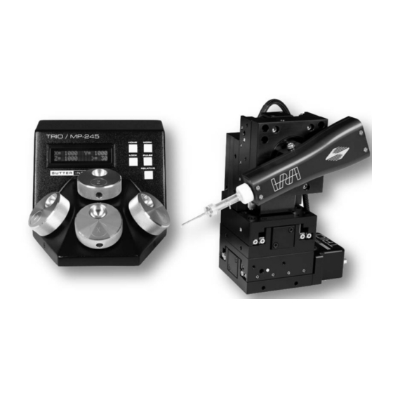
- Page 2 (The picture on the cover page shows a TRIO MP-245 ROE/controller and a TRIO MP-245/M micromanipulator. The Sutter Instrument IPA Headstage shown mounted on the micromanipulator is not included in the TRIO MP-245 Series system.) Copyright © 2020 Sutter Instrument Company. All Rights Reserved.
-
Page 5: Disclaimer
SAFETY WARNINGS AND PRECAUTIONS Electrical Operate the TRIO MP-245 using 110 – 240 VAC., 50-60 Hz line voltage. This instrument is designed for use in a laboratory environment that has low electrical noise and mechanical vibration. Surge suppression is recommended at all times NOTE: There are no user-replaceable fuses in the TRIO MP-245 system. -
Page 6: Other
Doing so can result in physical injury (e.g., fingers can be caught and pinched between the moving parts of the micromanipulator). If the TRIO MP-245 system is used in a microinjection environment, please observe the following. As with most micromanipulation devices, sharp micropipettes can fly out of their holder unexpectedly. -
Page 7: Table Of Contents
3.1 Main Controls and Indicators on the ROE/Controller ............... 21 3.2 Display .............................. 21 3.2.1 Initial Startup ........................... 21 3.3 Control Operations ......................... 22 3.3.1 Maximum Positive Position Values: ..................22 TRIO MP-245 THREE-AXIS MICROMANIPULATOR SYSTEM OPERATION MANUAL – REV. 2.67K (20201201) (FW V2.62) - Page 8 APPENDIX B. ACCESSORIES ......................44 APPENDIX C. TECHNICAL SPECIFICATIONS ................45 APPENDIX D. QUICK REFERENCE ....................47 D.1. Manual Operation ......................... 47 D.2. Configuration..........................47 D.3. External Control ........................... 48 TRIO MP-245 THREE-AXIS MICROMANIPULATOR SYSTEM OPERATION MANUAL – REV. 2.67K (20201201)
- Page 9 TABLE OF FIGURES Figure 1-1. The TRIO MP-245 system ..................... 9 Figure 2-1. Side view of TRIO MP-245/M showing mounting adapter plate and lock screws..13 Figure 2-2. Mounting the TRIO MP-245/M on the Adapter Plate ............14 Figure 2-3. Rear of TRIO MP-245 ROE/Controller cabinet ..............15 Figure 2-4.
- Page 10 Table D-9. TRIO MP-245 external control commands................. 50 Table D-10. Straight-Line Move ‘S’ Command Speeds for MP-245[S]/M-based configuration..53 Table D-11. Straight-Line Move ‘S’ Command Speeds for MP-285/M-based configuration.... 53 TRIO MP-245 THREE-AXIS MICROMANIPULATOR SYSTEM OPERATION MANUAL – REV. 2.67K (20201201)
-
Page 11: Introduction
Installation, which describes how to install, set up, and configure all components of the system; Chapter 3, Operations, which describes how to operate the TRIO MP-245; Chapter 4, Maintenance, describes how to perform routine and other maintenance; and Chapter 5, Reconfiguration, describes the reconfiguration possibilities of the TRIO MP-245 system. -
Page 12: Overview
TRIO MP-245 system. In the event that you need to transport the TRIO MP-245/M in the future, reapply 2 to 3-inch pieces of masking tape to the same locations. Once the tape has been removed, handle the TRIO MP-245/M with care. - Page 13 Finally, tapping the PULSE button causes a 3μm advance in the diagonal. This rapid burst of forward motion can assist in sharp electrode cell penetration. All the electronics, except for a small power supply, are housed within the TRIO MP-245 ROE and no separate controller or computer is required.
- Page 14 (This page intentionally left blank.) TRIO MP-245 THREE-AXIS MICROMANIPULATOR SYSTEM OPERATION MANUAL – REV. 2.67K (20201201)
-
Page 15: Installation
Locking Screws Figure 2-1. Side view of TRIO MP-245/M showing mounting adapter plate and lock screws. The TRIO MP-245/M is shipped with the adapter plate in place. It is attached using four tapered pegs, along with four locking screws. To remove it, first loosen the four hex screws that secure the manipulator to the pegs in the adapter plate. -
Page 16: Headstage Mounting
CAUTION: Unless the TRIO MP-245/M micromanipulator electromechanical baseplate is firmly bolted down to a breadboard or solidly to a firm surface, the TRIO MP-245/M is likely to tip over when fully extending all of its axes, especially if its loaded with a headstage that extends beyond the TRIO MP-245/M’s current center of gravity. -
Page 17: Roe/Controller Rear Panel Controls And Configuration
Upon deciding to directly install the TRIO MP-245 system in your rig, it is useful to follow the initial setup procedure to learn how to move the units to allow easy access to the mounting screws. 1. With the power switch on the back of the ROE in the OFF (0) position, connect the power adapter’s 24VDC cable to the POWER receptacle. -
Page 18: Configuration Switches
2.5.2 Configuration Switches Figure 2-4. Configuration switches on rear of TRIO MP-245 ROE/Controller unit (switch positions shown are factory defaults). 2.5.2.1 Switches 1, 2, 3 and 4: Knob Rotation Directionality for Forward (+) Movement These switches set the directionality for each of the four axes. -
Page 19: Switch 6: Sensor Test (Firmware < V2.2)
Calibration Homing on Power On Enabled: Calibrates to 1,000 µm for all axes on DOWN* power on. Power-off position is forgotten. * Factory default (recommended normal operation setting) TRIO MP-245 THREE-AXIS MICROMANIPULATOR SYSTEM OPERATION MANUAL – REV. 2.67K (20201201) (FW V2.62) -
Page 20: Switch 7: Pulse Button Functionality (Firmware V2.4)
TRIO MP-245/M electromechanical micromanipulator is 25mm, so Switch 9 should be set to OFF (up) (factory default for a standard TRIO MP-245 system). For a variant model with 12.5mm of travel in the Y axis, switch 9 must be set ON (down). -
Page 21: Switch 9 Electromechanical Device Compatibility (Firmware V2.62)
TRIO MP-245/M electromechanical micromanipulator is 25mm, so Switch 10 should be set to OFF (up) (factory default for a standard TRIO MP-245 system). For a variant model with 50mm of travel in the X axis, switch 10 must be set ON (down). - Page 22 (This page intentionally left blank.) TRIO MP-245 THREE-AXIS MICROMANIPULATOR SYSTEM OPERATION MANUAL – REV. 2.67K (20201201)
-
Page 23: Operations
Green) Figure 3-1. LCD Display showing startup screen. When starting the TRIO MP-245 system for the first time or if the HOME position has not yet been defined (saved), the values of all four axes will be 1,000 micrometers (microns). -
Page 24: Control Operations
3.3.4 Operating the Virtual D Axis The TRIO MP-245 consists of three physical axes, X, Y and Z. A tangent function utilizing X and Z axes and the angle of the holder has been implemented to create a virtual D axis. Use between 10°... -
Page 25: Moving To The Home Position
To move to the Work position, press the WORK button. If the current position before pressing WORK is less than the Work position, the movement will be as follows: TRIO MP-245 THREE-AXIS MICROMANIPULATOR SYSTEM OPERATION MANUAL – REV. 2.67K (20201201) (FW V2.62) -
Page 26: Setting Absolute/Relative Coordinates Mode
Green) Figure 3-11. Absolute mode 3.3.8 Mode Indications The TRIO MP-245 system has three modes of operation: Absolute coordinates, Relative coordinates, and Lock mode. The display turns color for each specific mode, as shown in the following table. TRIO MP-245 THREE-AXIS MICROMANIPULATOR SYSTEM OPERATION MANUAL – REV. 2.67K (20201201) -
Page 27: Speed Control And Roe Knob Movements (Speed)
3.4 Micropipette/Headstage Exchange Mounted on the front of the Z-axis of the manipulator is the angle-control plate for the headstage mount. TRIO MP-245 THREE-AXIS MICROMANIPULATOR SYSTEM OPERATION MANUAL – REV. 2.67K (20201201) (FW V2.62) -
Page 28: Figure 3-12. Angled Side View Of Trio Mp-245/M To Change Headstage Mount
Figure 3-12. Angled side view of TRIO MP-245/M to change headstage mount To change the headstage, loosen the screw in the center of the holding bracket. Slide the headstage upward out of the dovetail groove. Make any adjustments needed of the headstage, and then tighten down (but do not over tighten) the lock screw in the center of the holding bracket. -
Page 29: External Control
Controlling the TRIO MP-245 externally via computer is accomplished by sending commands over the USB interface between the computer and the USB connector on the rear panel of the TRIO MP-245 controller/ROE. The USB device driver for Windows is downloadable from Sutter Instrument’s web site (www.sutter.com). The TRIO MP-245 requires Sutter Instrument’s USB CDM (Combined Driver Model) Version 2.10.00 or higher. -
Page 30: Command Sequence Formatting
Little- Endian enforcement may be needed if running on a Big-Endian system. Some processors (e.g., ARM) can be configured for specific endianess. TRIO MP-245 THREE-AXIS MICROMANIPULATOR SYSTEM OPERATION MANUAL – REV. 2.67K (20201201) -
Page 31: Microsteps And Microns (Micrometers)
MP-285/M** micromanipulator * The same applies also to the MP-845[S]/M micromanipulator. ** The same applies also to the MP-265/M (discontinued) micromanipulator, 3DMS or MPC-78 stage, and SOM or MOM TRIO MP-245 MICROMANIPULATOR SYSTEM EXTERNAL CONTROL QUICK REFERENCE – REV. 2.67K (20201201) -
Page 32: Commands
WORK button. Y moves first, and X & Z last (angle determines order/simultaneity) Table 4-7. Move to controller -defined WORK position (‘w’) command. TRIO MP-245 THREE-AXIS MICROMANIPULATOR SYSTEM OPERATION MANUAL – REV. 2.67K (20201201) -
Page 33: Move To Specified "Home" Position ('H') Command
This command instructs the controller to move all three axes simultaneously in a straight Ranges line to specified position (see table). The command sequence consists of seventeen bytes. TRIO MP-245 MICROMANIPULATOR SYSTEM EXTERNAL CONTROL QUICK REFERENCE – REV. 2.67K (20201201) -
Page 34: Table 4-10. Straight-Line Move To Specified Position ('S') Command
1125.0 1125000 0.044291339 37.50% 0.9375 937.5 937500 0.036909449 31.25% 0.7500 750.0 750000 0.029527559 25.00% 0.5625 562.5 562500 0.022145669 18.75% 0.3750 375.0 375000 0.014763780 12.50% 0.1875 187.5 187500 0.007381890 6.25% TRIO MP-245 THREE-AXIS MICROMANIPULATOR SYSTEM OPERATION MANUAL – REV. 2.67K (20201201) -
Page 35: Interrupt Straight-Line Move ('^C') Command
<ETX> Command 0D 0000 1101 <CR> Completion indicator 4.3.8 Move to Specified X-Axis Position (‘x’ or ‘X’) Command This command moves to a specified position for only the X-axis. TRIO MP-245 MICROMANIPULATOR SYSTEM EXTERNAL CONTROL QUICK REFERENCE – REV. 2.67K (20201201) -
Page 36: Move To Specified Y-Axis Position ('Y' Or 'Y') Command
1 (4) Z µsteps 0000 1101 <CR> Completion indicator NOTE: All positions are in microsteps (µsteps): 32-bit (4 bytes) positive (unsigned) integer values, in Little Endian bit order (see Notes). TRIO MP-245 THREE-AXIS MICROMANIPULATOR SYSTEM OPERATION MANUAL – REV. 2.67K (20201201) -
Page 37: Setting The Angle ('A') Command
Use the same convention for other position variables the application might need. Declaring the microsteps/microns conversion factors in C/C++: /* conversion factors for the MP-845[S]/M based config. */ TRIO MP-245 MICROMANIPULATOR SYSTEM EXTERNAL CONTROL QUICK REFERENCE – REV. 2.67K (20201201) - Page 38 However, care should be taken to ensure that all relative position calculations always result in correct positive absolute positions before initiating a move command. Declaring relative position variables in C/C++: TRIO MP-245 THREE-AXIS MICROMANIPULATOR SYSTEM OPERATION MANUAL – REV. 2.67K (20201201)
- Page 39 Little-Endian byte order so byte reordering is not necessary before converting to/from 32-bit “long” values. LabVIEW always handles “byte strings” in “Big Endian” byte order irrespective of operating system and CPU, requiring that the four bytes TRIO MP-245 MICROMANIPULATOR SYSTEM EXTERNAL CONTROL QUICK REFERENCE – REV. 2.67K (20201201)
-
Page 40: Table 4-19. Straight-Line Move 'S' Command Speeds For Mp-845[S]/M-Based Configuration
1.1250 1125.0 1125000 0.044291339 37.50% 0.9375 937.5 937500 0.036909449 31.25% 0.7500 750.0 750000 0.029527559 25.00% 0.5625 562.50 562500 0.022145669 18.75% 0.3750 375.00 375000 0.014763780 12.50% 0.1875 187.50 187500 0.007381890 6.25% TRIO MP-245 THREE-AXIS MICROMANIPULATOR SYSTEM OPERATION MANUAL – REV. 2.67K (20201201) -
Page 41: Table 4-20. Straight-Line Move 'S' Command Speeds For Mp-285/M-Based Configuration
X axis fails to move, causing single- and multi-axis movement commands to fail. The ideal range for smooth movement is 10° to 80°. Factory default is 30°. TRIO MP-245 MICROMANIPULATOR SYSTEM EXTERNAL CONTROL QUICK REFERENCE – REV. 2.67K (20201201) - Page 42 (This page intentionally left blank.) TRIO MP-245 THREE-AXIS MICROMANIPULATOR SYSTEM OPERATION MANUAL – REV. 2.67K (20201201)
-
Page 43: Maintenance
5. MAINTENANCE Routine cleaning of the TRIO MP-245 system is required to prevent excessive dust accumulations. Wipe all exterior surfaces with a dry, soft, cotton cloth. Periodically inspect all cables and connections to make sure that all connections are made well and that all connectors are well and evenly seated. - Page 44 (This page intentionally left blank.) TRIO MP-245 THREE-AXIS MICROMANIPULATOR SYSTEM OPERATION MANUAL – REV. 2.67K (20201201)
-
Page 45: Appendix A. Limited Warranty
Warranty work will be performed only at the factory. The cost of shipment both ways is paid for by Sutter Instrument during the first three months this warranty is in effect, after which the cost is the responsibility of the customer. -
Page 46: Appendix B. Accessories
Tall gantry-stand 10.7 to 15.4 in (27.2 to 39.2 cm) MT-75XT Extra tall gantry-stand 14.7 to 18.5 in (37.4 to 47 cm) Risers can be combined to achieve desired height TRIO MP-245 THREE-AXIS MICROMANIPULATOR SYSTEM OPERATION MANUAL – REV. 2.67K (20201201) -
Page 47: Appendix C. Technical Specifications
System Power consumption 60-Watts maximum Mains fuses None replaceable (power protection built into the Power Adapter) Cables (Refer to the following tables for a description of all possible cables.) TRIO MP-245 MICROMANIPULATOR SYSTEM EXTERNAL CONTROL QUICK REFERENCE – REV. 2.67K (20201201) -
Page 48: Table C-1. Trio Mp-245 Cables And Receptacles/Connectors
5.5 x 7.5 x 4 in | 14 x 19 x 10.2cm Weight: TRIO MP-245 ROE/controller 2.3 lbs. | 1.04 kg TRIO MP-245M micromanipulator 3.5 lbs. | 1.6 kg TRIO MP-245 THREE-AXIS MICROMANIPULATOR SYSTEM OPERATION MANUAL – REV. 2.67K (20201201) -
Page 49: Appendix D. Quick Reference
**CAUTION: To avoid damage to the micromanipulator or stage, switch compatibility MP-285/M Down 6 (Sensor Test) must always be OFF (DOWN). 10 Reserved Off* NOTE: Travel length of each axis is automatically determined by end-of-travel sensor. TRIO MP-245 MICROMANIPULATOR SYSTEM EXTERNAL CONTROL QUICK REFERENCE – REV. 2.67K (20201201) -
Page 50: External Control
32-bit “long” or “double word”). For the Stop Bits TRIO MP-245, all axis position values (number of Parity None microsteps) are stored as “unsigned long” 32-bit TRIO MP-245 THREE-AXIS MICROMANIPULATOR SYSTEM OPERATION MANUAL – REV. 2.67K (20201201) -
Page 51: Table D-6. Microns/Microsteps Conversion
** The same applies also to the MP-265/M (discontinued) micromanipulator, 3DMS or MPC-78 stage, and SOM or MOM objective mover. NOTE: See Notes for speeds when making Straight-Line (‘S’ command) moves. TRIO MP-245 MICROMANIPULATOR SYSTEM EXTERNAL CONTROL QUICK REFERENCE – REV. 2.67K (20201201) -
Page 52: Table D-9. Trio Mp-245 External Control Commands
Target absolute positions of X, Y, & Z axes, in microsteps, each consisting of 4 contiguous bytes representing a single 32-bit unsigned (positive) integer value Ranges and bounds (see table) in Little-Endian bit order. 1 (4) X µsteps TRIO MP-245 THREE-AXIS MICROMANIPULATOR SYSTEM OPERATION MANUAL – REV. 2.67K (20201201) - Page 53 0000 0000 0000 <NUL> Angle in degrees between 0 and Angle Setting & 90. See 0101 1010 0090 ‘z’ Movement note 0000 1101 <CR> Completion indicator TRIO MP-245 MICROMANIPULATOR SYSTEM EXTERNAL CONTROL QUICK REFERENCE – REV. 2.67K (20201201)
- Page 54 ( ( rp_x_um < 0 && abs(rp_x_um) > cp_x_um ) || controller and that end of travel is not exceeded. All TRIO MP-245 THREE-AXIS MICROMANIPULATOR SYSTEM OPERATION MANUAL – REV. 2.67K (20201201)
-
Page 55: Table D-10. Straight-Line Move 'S' Command Speeds For Mp-245[S]/M-Based Configuration
This delay is not needed if “Interrupt Move” (^C) command, which can be issued while polling for return data. In either case, however, an an ‘S’ command-initiated move is still in progress. TRIO MP-245 MICROMANIPULATOR SYSTEM EXTERNAL CONTROL QUICK REFERENCE – REV. 2.67K (20201201) - Page 56 10° to 80°. Factory default is 30°. full movement is 1° to 89° (>0° and <90°). If 0° or 90°, Z or X axis fails to move, causing single- and multi-axis movement NOTES: TRIO MP-245 THREE-AXIS MICROMANIPULATOR SYSTEM OPERATION MANUAL – REV. 2.67K (20201201)
-
Page 57: Index
Move to specified Y-axis position command ... 36 configuration switches ......... 16 Move to specified Z-axis position command ... 37 knob rotation directionality for forward movement speeds ........41, 57 (+) movement ........16 TRIO MP-245 MICROMANIPULATOR SYSTEM EXTERNAL CONTROL QUICK REFERENCE – REV. 2.67K (20201201) - Page 58 LOCK Mode weight ..............50 ..............27 moving to the Home Position ...... 25 moving to the Work Position ....... 26 voltage pausing Home movements ......27 input ..............49 TRIO MP-245 THREE-AXIS MICROMANIPULATOR SYSTEM OPERATION MANUAL – REV. 2.67K (20201201)
- Page 59 WORK button (while moving to Work) ....27 12.5mm .............. 19 Y-Axis travel length 25mm ..............19 X-axis travel length Y-axis travel length (FW v2.4) ......19 25mm ..............20 50mm ..............20 NOTES: TRIO MP-245 MICROMANIPULATOR SYSTEM EXTERNAL CONTROL QUICK REFERENCE – REV. 2.67K (20201201)
- Page 60 NOTES: TRIO MP-245 THREE-AXIS MICROMANIPULATOR SYSTEM OPERATION MANUAL – REV. 2.67K (20201201)
Need help?
Do you have a question about the TRIO MP-245 and is the answer not in the manual?
Questions and answers