
Related Manuals for Sutter Instrument P-1000


Summary of Contents for Sutter Instrument P-1000
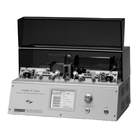
- Page 1 P-1000 Flaming/Brown™ Micropipette Puller System Operation Manual Rev. 3.02 ( 20161118) One Digital Drive Novato, CA 94949 Voice: 415-883-0128 Web: www.sutter.com Fax: 415-883-0572 Email: info@sutter.com...
- Page 2 Copyright © 2016 Sutter Instrument Company. All Rights Reserved. Flaming/Brown™ and Thermolock™ are trademarks of Sutter Instrument Company. P-1000 FLAMING/BROWN MICROPIPETTE PULLER SYSTEM OPERATION MANUAL – REV. 3.02 (20161118)
-
Page 5: Disclaimer
SAFETY WARNINGS AND PRECAUTIONS Electrical Operate the P-1000 using 110-120 V AC, 60 Hz, or 220-240 V AC., 50 Hz line voltage. This instrument is designed for connection to a standard laboratory power outlet (Overvoltage Category II), and because it is a microprocessor--controlled device, it should be accorded the same system wiring precautions as any 'computer type' system. -
Page 6: Back Injury Prevention
To avoid injuring your back or limbs it is recommended that you do not attempt to lift this instrument by yourself. The P-1000 Micropipette Puller weighs in excess of 16 kg (over 35 lb) and should be moved by TWO (2) people. -
Page 7: Table Of Contents
2.6 Editing a Program ..........................16 2.6.1 Installing a Program........................17 2.6.2 Patch Pipettes...........................18 2.6.3 Microinjection Pipettes and High Resistant Electrodes (30-300 Megohm).......18 2.6.4 Lock/Unlock Program......................18 2.6.5 Safe Heat Mode ........................19 P-1000 FLAMING/BROWN MICROPIPETTE PULLER SYSTEM OPERATION MANUAL – REV. 3.02 (20161118) - Page 8 4.8.3 Patch Pipette Fabrication .......................48 4.8.3.1 HEAT..........................49 4.8.3.2 PULL Strength........................49 4.8.3.3 VELOCITY (Trip Point)....................49 4.8.3.4 Cooling ..........................49 4.8.3.5 PRESSURE........................50 4.8.4 Thermolock™ Pre-Heat Mode ....................50 4.8.5 Step-by-Step Patch Pipette Programming ................53 P-1000 FLAMING/BROWN MICROPIPETTE PULLER SYSTEM OPERATION MANUAL – REV. 3.02 (20161118)
- Page 9 6.1.9 Problem: The shape and resistance of the pipette changes from pull to pull....69 6.2 System Operation/Function Problems ..................69 6.2.1 Startup Problems ........................70 6.2.2 General Operational Problems ....................70 6.2.3 On-Screen Emergency Reset Messages .................70 P-1000 FLAMING/BROWN MICROPIPETTE PULLER SYSTEM OPERATION MANUAL – REV. 3.02 (20161118)
- Page 10 Figure 2-3. Home Screen.........................10 Figure 2-4. Pulling a pipette........................11 Figure 2-5. Pull Report..........................12 Figure 2-6. View the pull report......................12 Figure 2-7. Ramp test..........................13 Figure 2-8. Ramp test result........................13 Figure 2-9. Menu Screen..........................14 P-1000 FLAMING/BROWN MICROPIPETTE PULLER SYSTEM OPERATION MANUAL – REV. 3.02 (20161118)
- Page 11 Figure 2-17. Delay mode of air-cooling....................20 Figure 2-18. Jaw temperature.........................20 Figure 2-19. Edit user notes........................21 Figure 3-1. P-1000 Cabinet (rear view), detailing power entry module, fuse-holder, fuse, and spare fuse holder..........................24 Figure 3-2. P-1000 Cabinet (end view, left), showing power switch...........24 Figure 4-1.
- Page 12 Table 6-4. On-screen error message in Edit/Pull Screen when Ramp value is not specified...71 Table 6-5. On-screen error messages in Edit/Pull screen when PULL is pressed......72 Table 6-6. Other on-screen error messages in Edit/Pull screen............72 P-1000 FLAMING/BROWN MICROPIPETTE PULLER SYSTEM OPERATION MANUAL – REV. 3.02 (20161118)
-
Page 13: General Information
The P-1000 is a ‘velocity sensing’ puller. This patented feature allows the puller to indirectly sense the viscosity of the glass, giving the P-1000 the ability to pull pipettes from all glasses except quartz. Even difficult to pull formulations, such as aluminosilicate glasses, are handled with relative ease. -
Page 14: Technical Support
Help Menu of the P-1000. 1.3 Technical Support Unlimited technical support is provided by Sutter Instrument Company at no charge to our customers. Our technical support staff is available between the hours of 8:00 AM and 5:00 PM (Pacific Standard Time) at (415) 883-0128. -
Page 15: System Description - Mechanical (Puller Anatomy)
Maintenance Section of this manual. 1.5.2 Air Cooling System The Model P-1000 supplies a blast of air to cool the filament area after the heating segment of a pull cycle. The components of the air-cooling system are shown below. -
Page 16: Heating Assembly
Figure 1-3. Filament block assembly. Figure 1-4. Heat sensor location on filament block assembly. P-1000 FLAMING/BROWN MICROPIPETTE PULLER SYSTEM OPERATION MANUAL – REV. 3.02 (20161118) -
Page 17: Upper Pulley Assembly
1-5), and contains a large eccentric adjustment screw (J in Figure 1-5). This eccentric screw is used to adjust cable ‘tension’. Its use is covered in the Maintenance Section, and changes P-1000 FLAMING/BROWN MICROPIPETTE PULLER SYSTEM OPERATION MANUAL – REV. 3.02 (20161118) -
Page 18: Figure 1-5. Upper Cable Pulley Assembly
Sutter Instrument Technical Support. Figure 1-5. Upper cable pulley assembly. Panels, Left And The panels are the angled surfaces that provide mountings for the Right Puller Bars and their Bearings, the Spring Stops, the Bumpers, and (K in Figure 1-5) the Upper Cable Pulley Assemblies. -
Page 19: Cabinet
1.5.6 Electronics The P-1000 micropipette puller is controlled by a dsPIC microprocessor. The HEAT power supply is a precision constant-current switching unit. The PULL supply is a constant-current DC power supply. The velocity trip point is set by a D-A converter. The output of the velocity transducer is compared to the output of the velocity D-A to determine when the trip velocity is reached. - Page 20 (This page intentionally blank.) P-1000 FLAMING/BROWN MICROPIPETTE PULLER SYSTEM OPERATION MANUAL – REV. 3.02 (20161118)
-
Page 21: Touchscreen User Interface Guide
Sutter for assistance. Figure 2-2. Startup fault report screen. NOTE: The P-1000 screen will go blank and into a Screensaver Mode after one hour. The green light around the Pull knob will slowly cycle on and off—pressing the [Pull] knob will WAKE the screen. -
Page 22: Home Screen
Press [Ramp] and follow the instructions. The Safe Heat Mode will be on (default settings) and a ramp value needs to P-1000 FLAMING/BROWN MICROPIPETTE PULLER SYSTEM OPERATION MANUAL – REV. 3.02 (20161118) -
Page 23: Figure 2-4. Pulling A Pipette
Heat-On-Time. You can review the detailed results of the two most recent pulls by selecting [Menu] and then [View Pull Results] P-1000 FLAMING/BROWN MICROPIPETTE PULLER SYSTEM OPERATION MANUAL – REV. 3.02 (20161118) -
Page 24: Pull Report
[View Pull Results] to view the report. Consistency of the Heat-On- Time and comparing the behavior of consecutive pulls can be useful tools in developing stable parameter settings. Figure 2-6. View the pull report. P-1000 FLAMING/BROWN MICROPIPETTE PULLER SYSTEM OPERATION MANUAL – REV. 3.02 (20161118) -
Page 25: Ramp Test
Safe heat Mode turned on to protect your filament. Heat settings 10% over or under the Ramp Value are both unstable and can cause damage to your filament and, when installed, will cause a warning. P-1000 FLAMING/BROWN MICROPIPETTE PULLER SYSTEM OPERATION MANUAL – REV. 3.02 (20161118) -
Page 26: Menu Screen
This helps to remove humidity and control for the ambient conditions in your lab. The default setting is 5 seconds. Time settings between 5-20 seconds are reasonable. P-1000 FLAMING/BROWN MICROPIPETTE PULLER SYSTEM OPERATION MANUAL – REV. 3.02 (20161118) -
Page 27: Air After Pull
Use the Sutter Pipette Cookbook feature to search for, select and install one of over 100 pre-designed programs stored in the P-1000. After installing a program and pulling a pipette, you can adjust the settings to modify and fine-tune the program. There are many standard Programs stored on the P-1000, which can be modified to serve your purpose. -
Page 28: Editing A Program
(10) lines. If only one line of programming is installed, the program will execute that line and pull the pipette in one stage. If the glass P-1000 FLAMING/BROWN MICROPIPETTE PULLER SYSTEM OPERATION MANUAL – REV. 3.02 (20161118) -
Page 29: Installing A Program
When pulling any type of pipette, it is best to first install a Cookbook program or a program you know worked well on a P-97 or P-1000 using the same glass and filament. Always run a new ramp test when installing a new program. If the program you install was established on a different puller with a different filament and/or glass size, you cannot expect the program to behave the same and make the same morphology of pipette. -
Page 30: Patch Pipettes
Type C and D can be used to make high resistant electrodes. 2.6.4 Lock/Unlock Program The program can be locked/unlocked in the [Menu] screen. Figure 2-14. Locking & unlocking a program (Menu screen). P-1000 FLAMING/BROWN MICROPIPETTE PULLER SYSTEM OPERATION MANUAL – REV. 3.02 (20161118) -
Page 31: Safe Heat Mode
An example of the TIME mode of air-cooling is shown in the following figure. The Time Mode is recommended when using thin walled glass. Figure 2-16. Time mode of air-cooling. P-1000 FLAMING/BROWN MICROPIPETTE PULLER SYSTEM OPERATION MANUAL – REV. 3.02 (20161118) -
Page 32: Jaw Temperature
This “shut down” protects the puller and filament assembly from damage due Figure 2-18. Jaw temperature. to overheating. When the jaws have sufficiently cooled, you can proceed to pull pipettes. P-1000 FLAMING/BROWN MICROPIPETTE PULLER SYSTEM OPERATION MANUAL – REV. 3.02 (20161118) -
Page 33: Edit User Notes
If the puller bars are held back and are not free to move, press the outer metal spring locks to free up the puller bars. Line 1 Heat = 0. Install a heat setting. P-1000 FLAMING/BROWN MICROPIPETTE PULLER SYSTEM OPERATION MANUAL – REV. 3.02 (20161118) - Page 34 This message shows if the glass does not soften after 60 seconds of heating. The Filament may have burned out (go to Menu/Diagnostics) or the Heat value may be too low. Perform a Ramp Test and use Safe Heat mode. P-1000 FLAMING/BROWN MICROPIPETTE PULLER SYSTEM OPERATION MANUAL – REV. 3.02 (20161118)
-
Page 35: Installation
3.2 Setting Up 3.2.1 Line Power (Mains) The P-1000 is designed to operate with a mains power of 110–220 V AC, at 50-60 Hz. The power cord provided with the P-1000 connects the grounded mains power outlet to the Power Entry Module located on the back of the unit (see diagram below). -
Page 36: Figure 3-1. P-1000 Cabinet (Rear View), Detailing Power Entry Module, Fuse-Holder, Fuse, And Spare Fuse Holder
Figure 3-1. P-1000 Cabinet (rear view), detailing power entry module, fuse-holder, fuse, and spare fuse holder. Make certain that the Power Switch located on the left end of the P-1000 cabinet is OFF ( Figure 3-2. P-1000 Cabinet (end view, left), showing power switch. -
Page 37: Operating Instructions
4. OPERATING INSTRUCTIONS 4.1 First Time Use While we realize that most new users of the P-1000 are anxious to start pulling useable pipettes right away, we cannot over-state the importance of taking a few moments to review the manual in order to understand how the puller works. Many a heating filament has been destroyed with first use due to not taking the time to understand the relationship between the programmable heat settings and the filament installed in the puller. -
Page 38: Figure 4-3. Using The Knob Or Keypad To Select A Program
A “beep” will sound and this message will appear instructing you to run a Ramp Test. Figure 4-4. Instruction to run ramp test. 8. Press “Ramp” on the touch-screen display to run a Ramp Test. P-1000 FLAMING/BROWN MICROPIPETTE PULLER SYSTEM OPERATION MANUAL – REV. 3.02 (20161118) -
Page 39: Figure 4-5. Running The Ramp Test
Do not over-tighten the knobs. CAUTION: The program HEAT value should not exceed the listed RAMP TEST value by more than 10%. The following shows how to load a piece of glass: P-1000 FLAMING/BROWN MICROPIPETTE PULLER SYSTEM OPERATION MANUAL – REV. 3.02 (20161118) -
Page 40: Figure 4-7. Loading A Piece Of Glass
(hour glass-shape) where the glass softened. 12. Once the Ramp Value has been reached, accept the ramp value. P-1000 FLAMING/BROWN MICROPIPETTE PULLER SYSTEM OPERATION MANUAL – REV. 3.02 (20161118) -
Page 41: Figure 4-9. Selecting A Ramp Value
If you’re ramp test value is 526, install 526 for your Heat. Heat settings within 5 to 10% of the ramp value are the most stable heat settings to use. P-1000 FLAMING/BROWN MICROPIPETTE PULLER SYSTEM OPERATION MANUAL – REV. 3.02 (20161118) -
Page 42: Figure 4-11. Using The Installed Ramp Value For Heat
16. With a new piece of glass and the Heat value installed, press the Pull button on the front panel. Press the PULL button on the front panel to start the Ramp Test Figure 4-12. Pressing PULL on front panel to start the ramp test. P-1000 FLAMING/BROWN MICROPIPETTE PULLER SYSTEM OPERATION MANUAL – REV. 3.02 (20161118) -
Page 43: Figure 4-13. Cycling Through A Looped 1-Line Program
Final Pull Results will display for 5 seconds. Press “Menu” then “Pull Results” to review. Figure 4-14. Brief display of Pull Results. P-1000 FLAMING/BROWN MICROPIPETTE PULLER SYSTEM OPERATION MANUAL – REV. 3.02 (20161118) -
Page 44: Figure 4-15. Making A Different Type Of Pipette Using The Sutter Cookbook
Warning will appear in the text box and disallow that heat setting. Change the heat setting to avoid damaging or burning out the filament. Safe Heat Mode <ON> Safe Heat Warning! Figure 4-16. Placing puller into Safe Heat Mode. P-1000 FLAMING/BROWN MICROPIPETTE PULLER SYSTEM OPERATION MANUAL – REV. 3.02 (20161118) -
Page 45: Default Configuration
3 - Patch pipette using 1.5 x 0.86 mm glass 4 - Pronuclear injection pipette using 1.0 x 0.78 mm glass 5 - Patch pipette using 1.5 x 1.1 mm glass P-1000 FLAMING/BROWN MICROPIPETTE PULLER SYSTEM OPERATION MANUAL – REV. 3.02 (20161118) - Page 46 The velocity of the glass carriage system is measured as the glass (Range 0-255) softens and begins to pull apart under a constant load. The increasing velocity of the initial pull is determined by the viscosity of P-1000 FLAMING/BROWN MICROPIPETTE PULLER SYSTEM OPERATION MANUAL – REV. 3.02 (20161118)
-
Page 47: Programs
4.2 Programs 4.2.1 Program Structure The resulting size and shape of a micropipette made using the P-1000 is determined by the parameter values that are programmed by the user. Up to 100 separate programs can be installed and saved. Each program is structured as follows: Program Consists of one or more Lines, each of which represents a pull cycle. -
Page 48: Program Line Pull Cycle Parameters
Useful changes in PULL strength are 10 units or more to see an effect. NOTE: A one-line program containing PULL = 0 and a low VELOCITY setting (15 – 40), looped 2-3 times, can be used for making short patch- type pipettes. P-1000 FLAMING/BROWN MICROPIPETTE PULLER SYSTEM OPERATION MANUAL – REV. 3.02 (20161118) - Page 49 = 0 (no active cooling). This allows the pulling of special pipette shapes. Most often used to pull long tube-likes shapes such as those used for aspiration, microperfusion, or holding. P-1000 FLAMING/BROWN MICROPIPETTE PULLER SYSTEM OPERATION MANUAL – REV. 3.02 (20161118)
-
Page 50: Pull Cycle
If DELAY is greater than 0 (zero), the air is activated for a short period and then the hard pull is activated after the specified DELAY. 4.2.4 Start Up. After switching on or after pressing RESET, the P-1000 tests the air and heating systems. The opening screen appears next Note on Entering Numbers: Numbers can be entered with the on-screen touch Keypad or with the Rotary Dial. -
Page 51: Figure 4-20. Examining The Contents Of A Program Using The Program Edit Screen
An alternate way in which a program can opened for viewing or editing is by pressing the Program List in main menu, and then selecting the program in the list shown in the following screen. P-1000 FLAMING/BROWN MICROPIPETTE PULLER SYSTEM OPERATION MANUAL – REV. 3.02 (20161118) -
Page 52: Editing A Program
), a warning is given if a Heat value differs from Ramp by more than 10%. 4.2.5.2 Edit User Notes By touching the blue text box at the bottom of your program you can bring up the “Edit User Notes” Screen. P-1000 FLAMING/BROWN MICROPIPETTE PULLER SYSTEM OPERATION MANUAL – REV. 3.02 (20161118) -
Page 53: Figure 4-22. Edit User Notes
Ramp Value (e.g., Heat = Ramp +10). The Rotary Dial allows cursor movement through the text. Cursor position is indicated by the character in which the cursor is positioned turning green. P-1000 FLAMING/BROWN MICROPIPETTE PULLER SYSTEM OPERATION MANUAL – REV. 3.02 (20161118) -
Page 54: Menu Screen
NOTE: The program option “Preheat Jaws 70˚C”in the Menu screen is associated with the Thermolock™ feature, and exists only in P-1000 systems that shipped on and after November 29 of 2010. Also, in the same systems, the Menu screen has both columnar titles ending in “Options”, replacing the previous “Operations”. -
Page 55: Ramp Test
4. As the glass begins to soften, a certain velocity of the puller bars moving apart is detected, at which point the heat turns off. 5. Once there is a small melt in the glass, the new ramp value will be displayed. P-1000 FLAMING/BROWN MICROPIPETTE PULLER SYSTEM OPERATION MANUAL – REV. 3.02 (20161118) -
Page 56: Heat Value Recommendations
10 seconds. The display will then report the number of heating cycles and the total time that the heat was turned on. Figure 4-25. Pull Report. P-1000 FLAMING/BROWN MICROPIPETTE PULLER SYSTEM OPERATION MANUAL – REV. 3.02 (20161118) -
Page 57: Figure 4-26. Sample Program
‘looping’. It will continue to do so until the glass separates. This looping capability is particularly useful for fabricating patch pipettes, which require multiple heating cycles to form the characteristic stubby geometry. P-1000 FLAMING/BROWN MICROPIPETTE PULLER SYSTEM OPERATION MANUAL – REV. 3.02 (20161118) -
Page 58: Notes On Program Operation
8 seconds after the <PULL> button is pressed. If the time is longer than eight seconds, and you are trying to pull a fine micropipette, increase the HEAT in 5 unit increments until P-1000 FLAMING/BROWN MICROPIPETTE PULLER SYSTEM OPERATION MANUAL – REV. 3.02 (20161118) -
Page 59: Pull Strength
TIME. Adjusting the cooling air pressure and/or switching to the Delay mode of active cooling are both more effective means of controlling tip length (see below). P-1000 FLAMING/BROWN MICROPIPETTE PULLER SYSTEM OPERATION MANUAL – REV. 3.02 (20161118) -
Page 60: Delay Mode (Cooling)
4.8.3 Patch Pipette Fabrication Micropipettes used for the electrophysiological recording technique of “patch clamping” are generally characterized by short, stubby shanks and relatively large diameter tips (> 0.7 P-1000 FLAMING/BROWN MICROPIPETTE PULLER SYSTEM OPERATION MANUAL – REV. 3.02 (20161118) -
Page 61: Heat
Hard pull is not activated (PULL = 0). More than one heating cycle is used. The P-1000 can be used very effectively for this type of processing. The following general information will familiarize you with the effect of adjusting each of the pull cycle parameters in a typical patch pipette program. -
Page 62: Pressure
<MENU> and then select the box to “Pre-Heat Jaws 70°C”. When using the Pre-Heat mode, air flush durations before and after the pull are increased to 10 sec. P-1000 FLAMING/BROWN MICROPIPETTE PULLER SYSTEM OPERATION MANUAL – REV. 3.02 (20161118) - Page 63 Heat mode might not function as intended. When the jaw temperature reaches 70°C, a green message bar is displayed indicating that it is okay to install the glass and pull a pipette. P-1000 FLAMING/BROWN MICROPIPETTE PULLER SYSTEM OPERATION MANUAL – REV. 3.02 (20161118)
- Page 64 70°C. If the jaw temperature has dropped to 70°C after the air flush, the pull cycle will begin immediately. P-1000 FLAMING/BROWN MICROPIPETTE PULLER SYSTEM OPERATION MANUAL – REV. 3.02 (20161118)
-
Page 65: Step-By-Step Patch Pipette Programming
3 loops the resulting pipette looks pretty reasonable. Let Y be equal to the VELOCITY value that results with the glass separating after 4 loops. Let Z P-1000 FLAMING/BROWN MICROPIPETTE PULLER SYSTEM OPERATION MANUAL – REV. 3.02 (20161118) -
Page 66: Technical Tips For Pulling Micropipettes
HEAT. To do this in a methodical fashion, increase the HEAT value in five unit increments, each time monitoring pull time until the pull takes place in less than eight seconds. P-1000 FLAMING/BROWN MICROPIPETTE PULLER SYSTEM OPERATION MANUAL – REV. 3.02 (20161118) -
Page 67: Pipette Position
(or taper) of a sharp pipette tip. The delay mode is often employed when using thick walled glass or for programs designed for the fabrication of pronuclear injection needles. P-1000 FLAMING/BROWN MICROPIPETTE PULLER SYSTEM OPERATION MANUAL – REV. 3.02 (20161118) -
Page 68: Fire Polishing
4.10 Fire Polishing The P-1000 micropipette puller allows you to perform light to moderate fire polishing of pipette tips but does not have a provision for visualizing the pipette tip during the heating process. The extent of the heating required to attain the desired degree of polishing must be empirically established. -
Page 69: Heating Filaments
(A or B in Figure 4-7). See the Filament Replacement section of the Maintenance Chapter for a full description of this adjustment. P-1000 FLAMING/BROWN MICROPIPETTE PULLER SYSTEM OPERATION MANUAL – REV. 3.02 (20161118) -
Page 70: Box Filament
4.11.3.1 Positioning When using a box filament, the glass tubing should be centered vertically and horizontally (Figure 4-30). See section 4.11.2 for adjustments and alignment. P-1000 FLAMING/BROWN MICROPIPETTE PULLER SYSTEM OPERATION MANUAL – REV. 3.02 (20161118) -
Page 71: Geometry
Note: The Ramp Test value with a trough filament will be lower than that with the box filament, thus program HEAT values will be correspondingly lower in order to reach similar operating temperatures. P-1000 FLAMING/BROWN MICROPIPETTE PULLER SYSTEM OPERATION MANUAL – REV. 3.02 (20161118) -
Page 72: Positioning
Table 4-3. Trough filament sizes. Filament Description FT315B 1.5mm wide trough FT320B 2mm wide trough FT330B (standard) 3mm wide trough FT345B 4.5mm wide trough P-1000 FLAMING/BROWN MICROPIPETTE PULLER SYSTEM OPERATION MANUAL – REV. 3.02 (20161118) -
Page 73: Maintenance
The correct position of the glass capillary in each of the two filament types is shown above in the Heating Filament section. This positioning is critical in achieving the desired pipette tip P-1000 FLAMING/BROWN MICROPIPETTE PULLER SYSTEM OPERATION MANUAL – REV. 3.02 (20161118) -
Page 74: Figure 5-2. Filament Alignment
Loosen the filament clamping screws and move the filament very slightly towards the side that produced the shorter pipette. Then tighten up the clamps and try another pull. You may have to go through several iterations before you get it centered properly. P-1000 FLAMING/BROWN MICROPIPETTE PULLER SYSTEM OPERATION MANUAL – REV. 3.02 (20161118) -
Page 75: Pulley Adjustment
The two cables should not be under high tension when the carriers are against their stops (the position they would be in just before pulling an electrode). P-1000 FLAMING/BROWN MICROPIPETTE PULLER SYSTEM OPERATION MANUAL – REV. 3.02 (20161118) -
Page 76: Regeneration Of Drierite Granules
The Indicating Drierite found in the canister at the right rear corner of the base plate on the P-1000 is a desiccant made of calcium sulfate (97%) and cobalt chloride (3%). This material is used to remove water vapor from the air-cooling supply system. The drierite granules become pink as they absorb moisture, eventually requiring that they be “regenerated”... -
Page 77: Reinstalling The Canister
If replacement is necessary, Indicating Drierite (8MESH with Indicator), manufactured by W.A. Hammond Drierite Co., Ltd. (Xenia, Ohio, USA), can be purchased from Sutter Instrument and most scientific supply distributors. P-1000 FLAMING/BROWN MICROPIPETTE PULLER SYSTEM OPERATION MANUAL – REV. 3.02 (20161118) - Page 78 (This page intentionally blank.) P-1000 FLAMING/BROWN MICROPIPETTE PULLER SYSTEM OPERATION MANUAL – REV. 3.02 (20161118)
-
Page 79: Troubleshooting
If however the HEAT is such that the pull takes place in more then 8 seconds, decreasing the cooling may somewhat decrease the tip size. Cooling P-1000 FLAMING/BROWN MICROPIPETTE PULLER SYSTEM OPERATION MANUAL – REV. 3.02 (20161118) -
Page 80: Problem: How Can The Size Of A Patch-Pipette Be Increased
P-1000 by decreasing air pressure, however a decreasing TIME may also be useful. 6.1.4 Problem: How can the size of a patch-pipette be increased? 1. The first thing to try is to reduce the HEAT on the last line of the program. Try dropping the HEAT 5 units at a time to see if this will increase the size of the tips. -
Page 81: Problem: The Shape And Resistance Of The Pipette Changes From Pull To Pull
Sutter Instruments. 6.2 System Operation/Function Problems The P-1000 has many built-in automated test capabilities. When the system starts up, the hardware is tested for normal operation and error messages are generated upon detection of a failure. Additionally, automated testing occurs before each pull. Finally, a diagnostics menu screen is provided, allowing for diagnostic testing on demand. -
Page 82: Startup Problems
If the problem recurs after allowing sufficient Heatsink temperature is 72 C time to cool down, the problem is likely due to a circuit fault, requiring repair at Sutter Instrument Company. P-1000 FLAMING/BROWN MICROPIPETTE PULLER SYSTEM OPERATION MANUAL – REV. 3.02 (20161118) -
Page 83: On-Screen Error Messages (Edit/Pull Screen)
Table 6-4. On-screen error message in Edit/Pull Screen when Ramp value is not specified. Error Message Possible Causes and Solutions A Ramp value is needed to use PreHeat If Jaw PreHeat is checked, a Ramp value greater than zero is needed. P-1000 FLAMING/BROWN MICROPIPETTE PULLER SYSTEM OPERATION MANUAL – REV. 3.02 (20161118) -
Page 84: Table 6-5. On-Screen Error Messages In Edit/Pull Screen When Pull Is Pressed
Perform a Ramp Test and use Safe Heat mode. Other error messages. Table 6-6. Other on-screen error messages in Edit/Pull screen. Error Message Possible Causes and Solutions Maximum 10 Program Lines Too many lines in your Program. P-1000 FLAMING/BROWN MICROPIPETTE PULLER SYSTEM OPERATION MANUAL – REV. 3.02 (20161118) -
Page 85: Diagnostics
6.3 Diagnostics The P-1000’s built-in diagnostics is started by selecting “Diagnostics” in the main menu screen. Figure 6-1. Starting Diagnostics from the Main Menu screen. The Diagnostics screen provides the means by which each P-1000’s hardware subsystem can be operated and tested independently. -
Page 86: Air Pressure System
This test also checks for air leakage from the system. 6.3.1.5 Air Valve (“Open/close the Air Valve”) This test verifies that the air valve opens correctly causing the displayed Pressure Transducer value to drop. P-1000 FLAMING/BROWN MICROPIPETTE PULLER SYSTEM OPERATION MANUAL – REV. 3.02 (20161118) -
Page 87: Test For Air Leaks
Heat setting, the Heat current is low. This can be due to a circuit board fault, but more often indicates a broken heat filament. Fault conditions are reported in red after the test, as shown in the following figure. P-1000 FLAMING/BROWN MICROPIPETTE PULLER SYSTEM OPERATION MANUAL – REV. 3.02 (20161118) -
Page 88: Pull Diagnostics
WARNING: With a Dial setting of 255 (the highest possible), a violent separation of the Puller Bars occurs during a Pull, which can cause injury. Use a rubber band rather than your fingers to hold the bars together for any value over 100. P-1000 FLAMING/BROWN MICROPIPETTE PULLER SYSTEM OPERATION MANUAL – REV. 3.02 (20161118) -
Page 89: Velocity Diagnostics
The “Puller bar end of travel sensor” shows “Tripped” when the bars are apart and “Not Tripped” when they are fully together. Adjust your Program Heat values to reflect the change in Ramp value. P-1000 FLAMING/BROWN MICROPIPETTE PULLER SYSTEM OPERATION MANUAL – REV. 3.02 (20161118) -
Page 90: Touchscreen Calibration
Figure 6-9. TouchScreen Calibration. Follow the instructions on the TouchScreen Calibration screen to calibrate. 6.5 Technical Support For further assistance, contact Sutter Instrument Technical Support at: (415) 883-0128 info@sutter.com P-1000 FLAMING/BROWN MICROPIPETTE PULLER SYSTEM OPERATION MANUAL – REV. 3.02 (20161118) -
Page 91: Appendix A. Limited Warranty
Warranty work will be performed only at the factory. The cost of shipment both ways is paid for by Sutter Instrument during the first three months this warranty is in effect, after which the cost is the responsibility of the customer. - Page 92 (This page intentionally blank.) P-1000 FLAMING/BROWN MICROPIPETTE PULLER SYSTEM OPERATION MANUAL – REV. 3.02 (20161118)
-
Page 93: Appendix B. Accessories
Platinum/iridium sheet, 18 x 75 x 0.05 mm (0.002in) Capillary Glass Tubing Several sizes and types of borosilicate and aluminosilicate glass tubes are available. Please refer to Sutter Instrument’s web site (www.sutter.com) for a list of part numbers. Other Accessories Spacer for special procedures (e.g., fire polishing) - Page 94 (This page intentionally blank.) P-1000 FLAMING/BROWN MICROPIPETTE PULLER SYSTEM OPERATION MANUAL – REV. 3.02 (20161118)
-
Page 95: Appendix C. Fuse Replacement
“active” when the holder is installed. A spare fuse is also stored within the fuse holder. Replace the active fuse with the spare and re-install the fuse holder and power cord. If the controller fails to power up with the new fuse installed, call Sutter Instrument technical support personnel for assistance. - Page 96 (This page intentionally blank.) P-1000 FLAMING/BROWN MICROPIPETTE PULLER SYSTEM OPERATION MANUAL – REV. 3.02 (20161118)
-
Page 97: Appendix D. Technical Specifications
10A, 250V, with safety ground plug Mains fuse (rear of cabinet) Time delay (or time lag) 5 x 20 mm glass tube. For specific fuse ratings, refer to Appendix C P-1000 FLAMING/BROWN MICROPIPETTE PULLER SYSTEM OPERATION MANUAL – REV. 3.02 (20161118) - Page 98 (This page intentionally blank.) P-1000 FLAMING/BROWN MICROPIPETTE PULLER SYSTEM OPERATION MANUAL – REV. 3.02 (20161118)
-
Page 99: Appendix E. Drierite Material Safety Data Sheet
N THE OBSTRUCTION OF AIRWAYS WITH SHORTNESS OF BREATH. INGESTION: MAY CAUSE VOMITING, DIARRHEA AND SENSATION OF WARMTH SIGNS AND SYMPTOMS OF OVER EXPOSURE: EYE, NOSE, THROAT, OR RESPIRATORY IRRITATION P-1000 FLAMING/BROWN MICROPIPETTE PULLER SYSTEM OPERATION MANUAL – REV. 3.02 (20161118) - Page 100 P-1000 FLAMING/BROWN MICROPIPETTE PULLER SYSTEM OPERATION MANUAL – REV. 3.02 (20161118)
-
Page 101: Index
.............2 ramp test ............43 fuse cycle holder..............83 definition ............. 34, 35 location .............. 83 replacement............83 spare..............83 date................. 34 fuses default configuration........33, 45 mains P-1000 FLAMING/BROWN MICROPIPETTE PULLER SYSTEM OPERATION MANUAL – REV. 3.02 (20161118) - Page 102 Pull Report ............12 Menu Screen ............14 pull time..............54 microinjection needle fabrication......46 puller bar ............... 28 microinjection pipettes......... 37 adjustment ............6 Microinjection Pipettes ........18 alignment .............6 P-1000 FLAMING/BROWN MICROPIPETTE PULLER SYSTEM OPERATION MANUAL – REV. 3.02 (20161118)
- Page 103 View Pull Results..........11, 12 power cord ............. 85 weight ..............85 technical support .............2 warranty..............79 Technical Support ..........78 weight ..............85 Thermolock™............14 write protection............. 34 P-1000 FLAMING/BROWN MICROPIPETTE PULLER SYSTEM OPERATION MANUAL – REV. 3.02 (20161118)
- Page 104 NOTES P-1000 FLAMING/BROWN MICROPIPETTE PULLER SYSTEM OPERATION MANUAL – REV. 3.02 (20161118)
Need help?
Do you have a question about the P-1000 and is the answer not in the manual?
Questions and answers