Sign In
Upload
Manuals
Brands
Sutter Instrument Manuals
Laboratory Equipment
LAMBDA 10-B
Sutter Instrument LAMBDA 10-B Manuals
Manuals and User Guides for Sutter Instrument LAMBDA 10-B. We have
1
Sutter Instrument LAMBDA 10-B manual available for free PDF download: Operation Manual
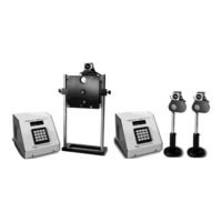
Sutter Instrument LAMBDA 10-B Operation Manual (116 pages)
Optical Filter Changer and SmartShutter® Control System
Brand:
Sutter Instrument
| Category:
Laboratory Equipment
| Size: 3 MB
Table of Contents
Safety Warnings and Precautions
5
Electrical
5
Avoiding Electrical Shock and Fire-Related Injury
5
Optical Radiation
6
Electromagnetic Interference
6
Operational
6
Table of Contents
9
General Information
15
Introduction
15
How to Use this Manual
15
Technical Support
15
General Description
15
Filter Wheel
16
Mechanical Description
16
Supported Filter Wheel and Shutter Configurations
17
Figure 1-1. Lambda Series 25Mm Filter Wheel (Without Shutter)
17
Figure 1-2. Lambda Series 25Mm Filter Wheel Housing (with 25Mm Shutter)
17
Figure 1-3. Lambda-Series 25Mm Filter Wheel Housing with 25Mm Smartshutter and 32Mm Filter Wheel Housing with 35Mm Smartshutter
17
Filter Wheel and Shutter Configurations NOT Supported
18
Filter Wheels
18
Mechanical Description
19
Filters
19
Slide-In or Drop-In Filter Holders
19
Filter Wheel Adapters
20
Shutters
20
Smartshutter Mounts
20
Cables
21
Devices for TTL-Control of Shutters
21
Adapters
21
Smartshutter
21
Step Motor Based Shutter Advantages
21
Figure 1-4. 25Mm Smartshutter Standalone and Mounted on the Housing of a 25Mm Filter Wheel
22
Modes
23
Special Considerations
23
Mounting
23
Figure 1-5. 35Mm Smartshutter Standalone and Mounted on the Housing of a 32Mm Filter Wheel
23
Opening and Closing Times
24
Figure 1-6. Smartshutter Timing
24
Repetition Rates and Duty Cycle
25
Controller
25
Principles of Operation
25
Rear Panel Connectors
25
Figure 1-7 Rear Panel Electrical Connections
26
Front Panel Controls
27
Keypad
27
Figure 1-8. LAMBDA 10-B Front Panel Controls
27
Display
28
Functional Description
28
Stepping Motor Operation
28
Installation
31
Unpacking
31
Pre-Installation Considerations
32
Vibrations
32
Installing the Filter Wheel
33
Figure 2-1. Schematic Diagram of Two Possible Experimental Configurations
33
Filter Wheel Assembly
34
Figure 2-2. Filter Wheel-Mounting Stand
34
Loading Filters
35
Filter Orientation
35
Filter Cups and Filter Holders
35
Figure 2-3. Filter Wheel Connection
35
Figure 2-4. Filter Holder Components
36
Installation of Filters into Filter Holders
37
Figure 2-5. Changing Filters in the Slide-In Filter Holder
37
Table 2-1. Maximum Allowable Filter Thickness
37
Figure 2-6. Removing the Retaining Ring
38
Figure 2-7. Assembly Order of Filter Holder Parts
38
Installation of Filters into Filter Cups
39
Figure 2-8. Filter Ports (Plug Is Removed from the Loading Port)
39
Filter Loading Tips
40
Selection of a Filter Position
40
Use of Blanking Discs
40
Neutral Density Filters
40
Shutter Options
41
Mounting a Smartshutter in a Lambda LS
41
Operations
43
First Time Use
43
Line Power (Mains)
43
Figure 3-1. LAMBDA 10-B Cabinet (Rear View)
43
Figure 3-2. Switch, Fuse, and Power Connection
43
Basic Operation
44
Initialization
44
Figure 3-3. Power Connection
44
Make It Go
45
Operations: Manual Control
47
Power up Sequence
47
Main Status Screen
47
Filter Wheel/Shutter Configuration
47
Dual-Smartshutter Configuration
47
Placing LAMBDA 10-B into Local Mode
48
Immediate Key Control of Attached Devices
48
Filter Wheel And/Or Shutter Configuration
48
Main Menu (F1)
48
TTL Shutter Control Menu (F1 1)
49
Configuring TTL Shutter Control for Open on High (F1 1 1 1)
49
Configuring TTL Shutter Control for Open on Low (F1 1 1 2)
49
Configuring TTL Shutter Control for Toggling Open and Close on High (F1 1 1 3)
49
Test Mode Menu (F1 2)
49
Loop Test (F1 2 1)
49
Speed Test (F1 2 2)
50
Shutter Test (F1 2 3)
50
Demo (F1 2 4)
50
Smartshutter Mode Menu (F1 3)
50
Fast Mode (F1 3 1)
50
Soft Mode (F1 3 2)
50
Neutral Density Mode (F1 3 3)
50
Configuration Menu (F1 4)
50
Save Configuration (F1 4 1)
51
Restore Configuration (F1 4 2)
51
Selecting the Filter Position
51
Selecting the Filter Switching Speed
51
Selecting the Shutter Position (Open/Close)
52
Shutter Movement Errors: Causes and Solutions
52
Error Detection and Recovery
52
Table 4-1. Filter Switching Times (in Milliseconds)
52
Movement Errors: Causes and Solutions
53
Helpful Tips about Movement Errors
54
Smart Shutter Movement Errors: Causes and Solutions
54
Movement Errors after Successive Moves
54
External Command Control Operations Overview
57
Input Command Structure
57
Commands Description
57
Table 5-1. Remote Control Command Categories
57
Table 5-2. External Commands
58
Filter Wheel Commands
60
Filter Wheel Command Byte Encoding
61
Table 5-3. Filter Command Structure
61
Table 5-4. Codes for Filter Wheel Configuration
62
Shutter Commands
65
Table 5-5. Shutter Open/Close Commands
65
Table 5-6. Smartshutter Mode Commands in the "Wheel/Shutter" Configuration
66
Table 5-7. Smartshutter Mode Commands in the "Dual-Smartshutter" Configuration
66
Open Shutter a
67
Open Shutter a Conditionally
67
Close Shutter a
67
Open Shutter B
67
Open Shutter B Conditionally
67
Close Shutter B
67
Fast-Mode Shutter
67
Soft-Mode Shutter
68
Neutral Density Mode Shutter
68
Special Commands
68
Table 5-8. Special Command Codes
68
Status
69
Table 5-9. "Get Status" Command Return Data in a "Wheel & Shutter" Configuration
69
Table 5-10. "Get Status" Command Return Data in a "Dual-Smartshutter" Configuration
70
All Motors Power on
71
All Motors Power off
71
Transfer to on Line
71
Transfer to Local
71
Reset
71
Get Controller Type and Configuration
71
Table 5-11. "Get Controller Type and Configuration" Command Return Data in a Wheel & Shutter Configuration
72
Table 5-12. "Get Controller Type and Configuration" Command Return Data in a Dual-Smartshutter Configuration
72
Shutter Control Without Remote Control Commands Via the Dedicated TTL Line
73
Remote Control Command Programming
73
Preparing the Command Byte
73
Encoding Filter Commands into a Single Byte
73
Shutter or Special Commands
74
Command Transmission Protocol
74
Confirmation Command Echo
74
Command Completion Indicator
74
External Serial Rs-232 Interface Control
75
Connecting to the Serial Port
75
Figure 6-1. Serial Port Pin Assignments
75
Input Command Set and Protocol
76
Table 6-1. Serial Interface Serial Port Settings
76
External Usb Interface Control
77
Table 7-1. USB Interface Serial Port Settings
77
Table 7-2. USB Interface Serial Port Settings (Later Firmware)
77
Installation Steps
78
Figure 7-1. the USB Cable Device Connector and Device USB Receptacle
78
Installing the LAMBDA 10-B as a USB Device on a Windows System Using the Standard Device Driver
79
Figure 7-2. Host Connector End of USB Cable and USB Host Receptacle on Remote Computer
79
Figure 7-3. New USB Device Detected Message Box
79
Figure 7-4. Digital Signature Dialog Box
80
Figure 7-5. Specifying Location of Driver Files
80
Installing the LAMBDA 10-B as a USB Device on a Windows System Using CDM (Combined Driver Model) Device Driver
81
Figure 7-6. Browsing for the Driver File Needed
81
Installing the USB Interface for Non-Windows Systems
82
Verifying USB Communication between Remote Computer and LAMBDA 10-B
82
Uninstalling the USB Driver for the LAMBDA 10-B
83
Remote Commands and the USB Interface
83
Command Sequence Formatting and Protocol
84
Confirmation Command Echo
84
Command Completion Indicator
84
Operating Instructions: External Logic Level (Ttl) Shutter Control
85
Using the Pc's Parallel Port for Control
85
Table 8-1. Commands for PC Parallel Port Control of Dedicated TTL Line
85
Maintenance
87
Appendix A. Limited Warranty
89
Appendix B. Accessories
91
Filter Wheels
91
Smartshutter
92
Appendix C. Fuse Replacement
93
Figure C-1. Power Entry Module and Fuse Holder
93
Appendix D. Technical Specifications
95
Table D-1. Controller Cables
97
Appendix E. Lambda 10-B Rev C and Earlier Versions
99
Appendix F. External Control Command Reference
101
Manual Operation
101
Configuration
101
External Control
102
Table F-1. Commands for PC Parallel Port Control of Dedicated TTL Line
102
Table F-2. Serial and USB- Interface Serial Port Settings
102
Table F-3. USB Interface Serial Port Settings (Later Firmware)
102
Table F-4. Complete Command Reference
103
Table F-5. Filter Command Structure
105
Table F-6. Codes for Filter Wheel Configuration
106
Table F-7. "Get Status" Command Return Data in a "Wheel & Shutter" Configuration
109
Table F-8. "Get Status" Command Return Data in a "Dual-Smartshutter" Configuration
110
Table F-9. "Get Controller Type and Configuration" Command Return Data in a Wheel & Shutter Configuration
111
Table F-10. Get Controller Type and Configuration" Command Return Data in a Dual-Smartshutter Configuration
111
Advertisement
Advertisement
Related Products
Sutter Instrument Lambda 10-3
Sutter Instrument Lambda DG-4
Sutter Instrument Lambda DG-5
Sutter Instrument Lambda 10-2
Sutter Instrument Lambda 10-232S
Sutter Instrument Lambda 10-250
Sutter Instrument Lambda 10-232
Sutter Instrument Lambda 10-2S
Sutter Instrument 148006
Sutter Instrument Lambda 421
Sutter Instrument Categories
Laboratory Equipment
Amplifier
Control Systems
Controller
Work Light
More Sutter Instrument Manuals
Login
Sign In
OR
Sign in with Facebook
Sign in with Google
Upload manual
Upload from disk
Upload from URL